2009 NISSAN LATIO trunk
[x] Cancel search: trunkPage 716 of 4331
NATS (NISSAN ANTI-THEFT SYSTEM)
BL-255
< SERVICE INFORMATION >
C
D E
F
G H
J
K L
M A
B BL
N
O P
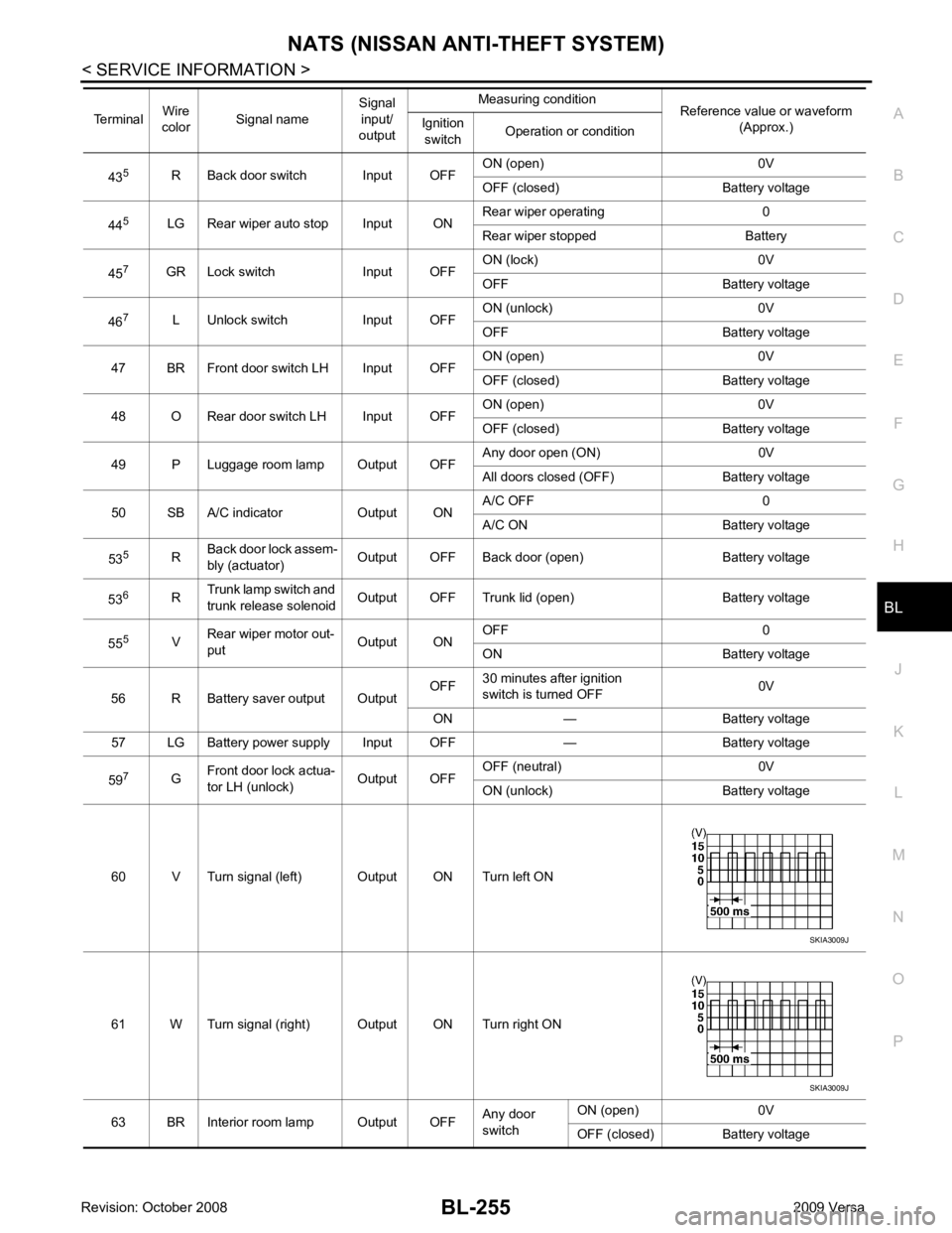
43
5
R Back door switch Input OFF ON (open) 0V
OFF (closed) Battery voltage
44 5
LG Rear wiper auto stop Input ON Rear wiper operating 0
Rear wiper stopped Battery
45 7
GR Lock switch Input OFF ON (lock) 0V
OFF Battery voltage
46 7
L Unlock switch Input OFF ON (unlock) 0V
OFF Battery voltage
47 BR Front door switch LH Input OFF ON (open) 0V
OFF (closed) Battery voltage
48 O Rear door switch LH Input OFF ON (open) 0V
OFF (closed) Battery voltage
49 P Luggage room lamp Output OFF Any door open (ON) 0V
All doors closed (OFF) Battery voltage
50 SB A/C indicator Output ON A/C OFF 0
A/C ON Battery voltage
53 5
RBack door lock assem-
bly (actuator) Output OFF Back door (open) Battery voltage
53 6
RTrunk lamp switch and
trunk release solenoid Output OFF Trunk lid (open) Battery voltage
55 5
VRear wiper motor out-
put Output ONOFF 0
ON Battery voltage
56 R Battery saver output Output OFF
30 minutes after ignition
switch is turned OFF 0V
ON — Battery voltage
57 LG Battery power supply Input OFF — Battery voltage
59 7
GFront door lock actua-
tor LH (unlock) Output OFFOFF (neutral) 0V
ON (unlock) Battery voltage
60 V Turn signal (left) Output ON Turn left ON
61 W Turn signal (right) Output ON Turn right ON
63 BR Interior room lamp Output OFF Any door
switch ON (open) 0V
OFF (closed) Battery voltage
Terminal
Wire
color Signal name Signal
input/
output Measuring condition
Reference value or waveform
(Approx.)
Ignition
switch Operation or condition SKIA3009J
SKIA3009J
Page 2892 of 4331
EI
N
O P
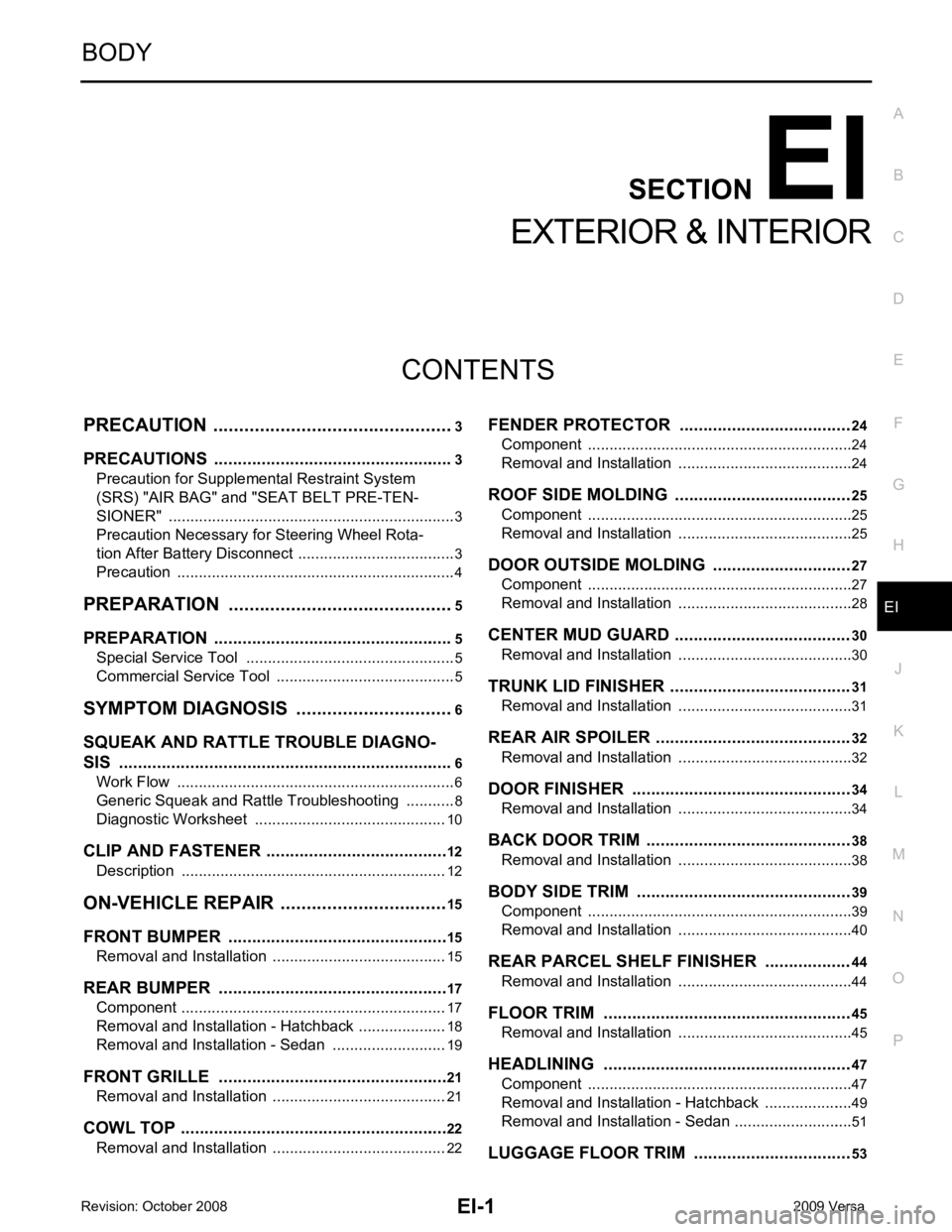
CONTENTS
EXTERIOR & INTERIOR
PRECAUTION ....... ........................................3
PRECAUTIONS .............................................. .....3
Precaution for Supplemental Restraint System
(SRS) "AIR BAG" and "SEAT BELT PRE-TEN-
SIONER" ............................................................. ......
3
Precaution Necessary fo r Steering Wheel Rota-
tion After Battery Disconnect ............................... ......
3
Precaution ........................................................... ......4
PREPARATION .... ........................................5
PREPARATION .............................................. .....5
Special Service Tool ........................................... ......5
Commercial Service Tool .................................... ......5
SYMPTOM DIAGNOSIS ..... ..........................6
SQUEAK AND RATTLE TROUBLE DIAGNO-
SIS .................................................................. .....6
Work Flow ........................................................... ......6
Generic Squeak and Rattle Troubleshooting ...... ......8
Diagnostic Worksheet ......................................... ....10
CLIP AND FASTENER ................................... ....12
Description .......................................................... ....12
ON-VEHICLE REPAIR .... .............................15
FRONT BUMPER ........................................... ....15
Removal and Installation .........................................15
REAR BUMPER ............................................. ....17
Component .......................................................... ....17
Removal and Installation - Hatchback .....................18
Removal and Installation - Sedan ....................... ....19
FRONT GRILLE ............................................. ....21
Removal and Installation .........................................21
COWL TOP ..................................................... ....22
Removal and Installation .........................................22 FENDER PROTECTOR ....................................
24
Component .......................................................... ....24
Removal and Installation ..................................... ....24
ROOF SIDE MOLDING ..................................... 25
Component .......................................................... ....25
Removal and Installation ..................................... ....25
DOOR OUTSIDE MOLDING ............................. 27
Component .......................................................... ....27
Removal and Installation ..................................... ....28
CENTER MUD GUARD ..................................... 30
Removal and Installation ..................................... ....30
TRUNK LID FINISHER ...................................... 31
Removal and Installation ..................................... ....31
REAR AIR SPOILER ......................................... 32
Removal and Installation ..................................... ....32
DOOR FINISHER .............................................. 34
Removal and Installation ..................................... ....34
BACK DOOR TRIM ........................................... 38
Removal and Installation ..................................... ....38
BODY SIDE TRIM ............................................. 39
Component .......................................................... ....39
Removal and Installation ..................................... ....40
REAR PARCEL SHELF FINISHER .................. 44
Removal and Installation ..................................... ....44
FLOOR TRIM .................................................... 45
Removal and Installation ..................................... ....45
HEADLINING .................................................... 47
Component .......................................................... ....47
Removal and Installation - Hatchback ................. ....49
Removal and Installation - Sedan ........................ ....51
LUGGAGE FLOOR TRIM ................................. 53
Page 2900 of 4331
EI
N
O P
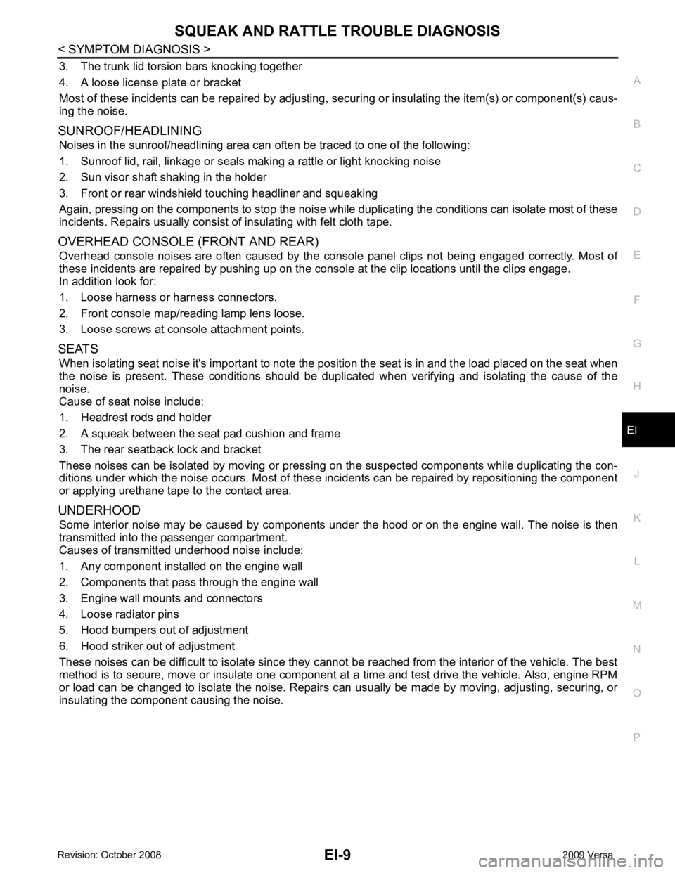
3. The trunk lid torsion bars knocking together
4. A loose license plate or bracket
Most of these incidents can be repaired by adjusting, se curing or insulating the item(s) or component(s) caus-
ing the noise.
SUNROOF/HEADLINING Noises in the sunroof/headlining area can often be traced to one of the following:
1. Sunroof lid, rail, linkage or seals making a rattle or light knocking noise
2. Sun visor shaft shaking in the holder
3. Front or rear windshield touching headliner and squeaking
Again, pressing on the components to stop the noise while duplicating the conditions can isolate most of these
incidents. Repairs usually consist of insulating with felt cloth tape.
OVERHEAD CONSOLE (FRONT AND REAR) Overhead console noises are often caused by the cons ole panel clips not being engaged correctly. Most of
these incidents are repaired by pushing up on the c onsole at the clip locations until the clips engage.
In addition look for:
1. Loose harness or harness connectors.
2. Front console map/reading lamp lens loose.
3. Loose screws at console attachment points.
SEATS When isolating seat noise it's important to note the pos ition the seat is in and the load placed on the seat when
the noise is present. These conditions should be duplic ated when verifying and isolating the cause of the
noise.
Cause of seat noise include:
1. Headrest rods and holder
2. A squeak between the seat pad cushion and frame
3. The rear seatback lock and bracket
These noises can be isolated by moving or pressing on the suspected components while duplicating the con-
ditions under which the noise occurs. Most of thes e incidents can be repaired by repositioning the component
or applying urethane tape to the contact area.
UNDERHOOD Some interior noise may be caused by components under the hood or on the engine wall. The noise is then
transmitted into the passenger compartment.
Causes of transmitted underhood noise include:
1. Any component installed on the engine wall
2. Components that pass through the engine wall
3. Engine wall mounts and connectors
4. Loose radiator pins
5. Hood bumpers out of adjustment
6. Hood striker out of adjustment
These noises can be difficult to isolate since they cannot be reached from the interior of the vehicle. The best
method is to secure, move or insulate one component at a time and test drive the vehicle. Also, engine RPM
or load can be changed to isolate the noise. Repairs c an usually be made by moving, adjusting, securing, or
insulating the component causing the noise.
Page 2910 of 4331
EI
N
O P
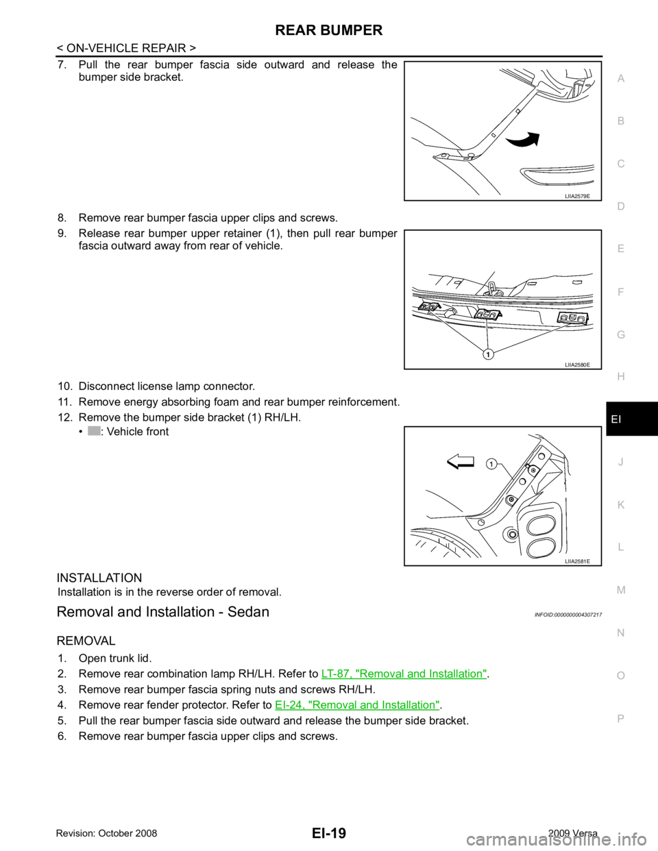
7. Pull the rear bumper fascia side outward and release the
bumper side bracket.
8. Remove rear bumper fascia upper clips and screws.
9. Release rear bumper upper retainer (1), then pull rear bumper fascia outward away from rear of vehicle.
10. Disconnect license lamp connector.
11. Remove energy absorbing foam and rear bumper reinforcement.
12. Remove the bumper side bracket (1) RH/LH. • : Vehicle front
INSTALLATION Installation is in the reverse order of removal.
Removal and Installation - Sedan INFOID:0000000004307217
REMOVAL 1. Open trunk lid.
2. Remove rear combination lamp RH/LH. Refer to LT-87, " Removal and Installation " .
3. Remove rear bumper fascia spring nuts and screws RH/LH.
4. Remove rear fender protector. Refer to EI-24, " Removal and Installation " .
5. Pull the rear bumper fascia side outward and release the bumper side bracket.
6. Remove rear bumper fascia upper clips and screws. LIIA2580E
Page 2922 of 4331
EI
N
O P
TRUNK LID FINISHER
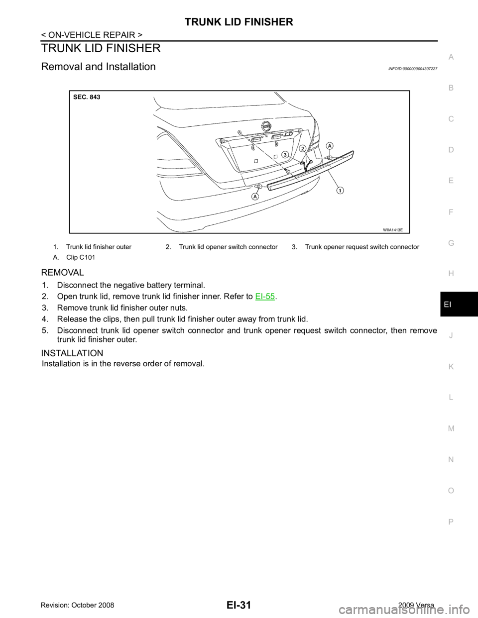
Removal and Installation INFOID:0000000004307227
REMOVAL 1. Disconnect the negative battery terminal.
2. Open trunk lid, remove trunk lid finisher inner. Refer to EI-55 .
3. Remove trunk lid finisher outer nuts.
4. Release the clips, then pull trunk lid finisher outer away from trunk lid.
5. Disconnect trunk lid opener switch connector and tr unk opener request switch connector, then remove
trunk lid finisher outer.
INSTALLATION Installation is in the reverse order of removal. 1. Trunk lid finisher outer 2. Trunk lid opener switch connector 3. Trunk opener request switch connector
A. Clip C101
Page 2924 of 4331
EI
N
O P
2. Remove the rear spoiler nuts.
3. Remove inside trunk lid finisher. Refer to EI-55, " Removal and Installation " .
4. Disconnect high mounted stop lamp connector.
5. Release adhesive backed foam tape and clips, then carefully lift the rear air spoiler from trunk lid. CAUTION:
Use care not to damage painted surfaces during removal, or releasing of adhesive backed foam
tapes if equipped.
6. Release the high mounted stop lamp harness grommet from trunk lid, then remove rear air spoiler.
Installation - Sedan Installation is in the reverse order of removal.
NOTE:
• Before installing rear air spoiler, clean the surface where it will be mounted with isopropyl alcohol or equiva-
lent to degrease the surface.
• Before installing, be sure there are no gaps or wa ves in the foam tape (if equipped) where the surfaces
meet.
• During installation, be sure grommet of high mounted stop lamp harness is fully seated into trunk lid opening
prior to final rear air spoiler placement.
Removal - Hatchback 1. Disconnect the negative battery terminal.
2. Remove back door finisher upper. Refer to EI-38 .
3. Disconnect high mounted stop lamp connector.
4. Remove the nuts and carefully lift the rear air spoiler from the back door. CAUTION:
Use care not to damage painted surfaces during removal, or releasing of adhesive backed foam
tapes if equipped.
5. Release the high mounted stop lamp harness grommet from back door, then remove rear air spoiler.
Installation - Hatchback Installation is in the reverse order of removal.
NOTE:
• Before installing rear air spoiler, clean the surface where it will be mounted with isopropyl alcohol or equiva-
lent to degrease the surface.
• Before installing, be sure there are no gaps or wa ves in the foam tape (if equipped) where the surfaces
meet.
• During installation, be sure grommet of high mount ed stop lamp harness is fully seated into back door open-
ing prior to final rear air spoiler placement.
Page 2946 of 4331
EI
N
O P
TRUNK ROOM TRIM & TRUNK LID FINISHER
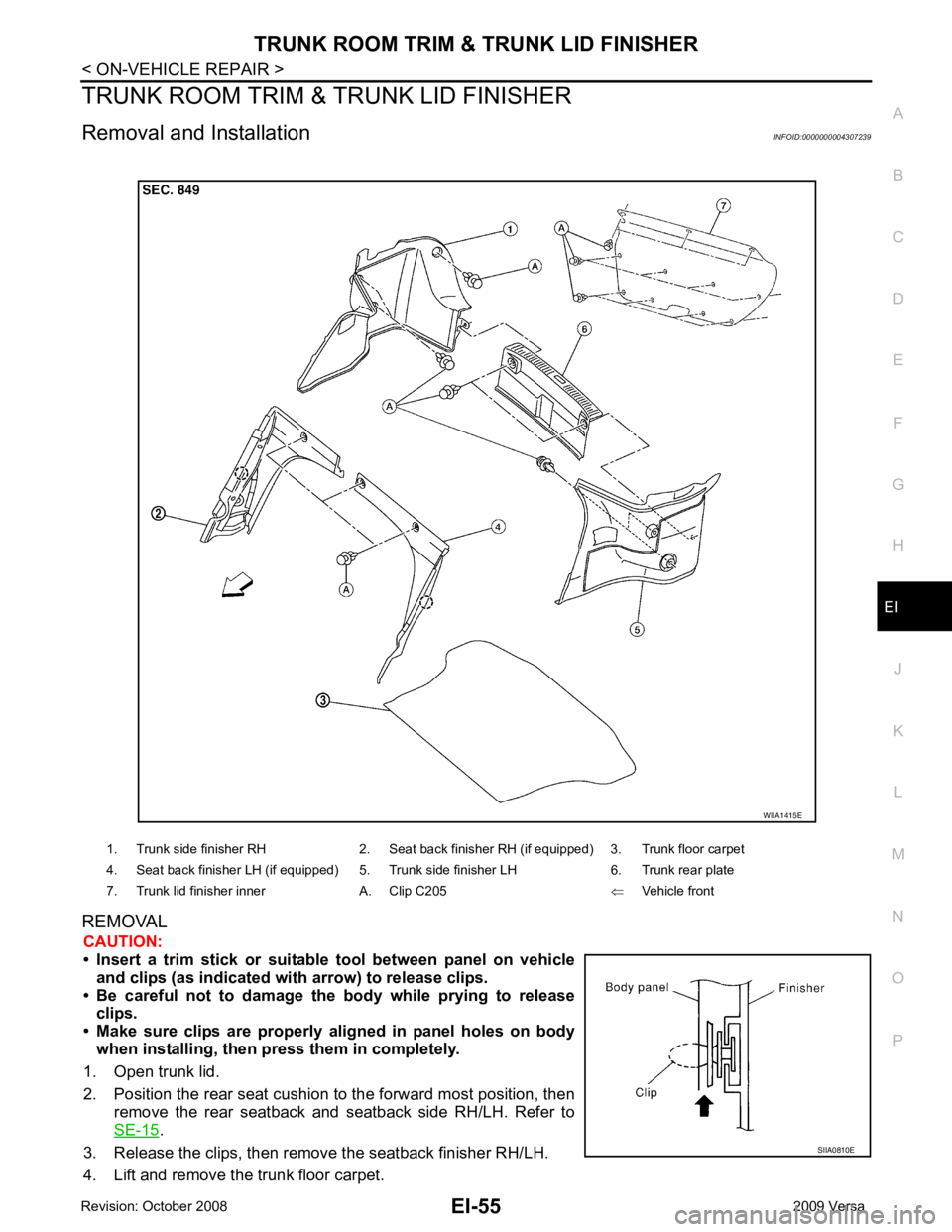
Removal and Installation INFOID:0000000004307239
REMOVAL CAUTION:
• Insert a trim stick or suitable tool between panel on vehicle
and clips (as indicated with arrow) to release clips.
• Be careful not to damage the body while prying to release clips.
• Make sure clips are properly al igned in panel holes on body
when installing, then press them in completely.
1. Open trunk lid.
2. Position the rear seat cushion to the forward most position, then remove the rear seatback and seatback side RH/LH. Refer to
SE-15 .
3. Release the clips, then remove the seatback finisher RH/LH.
4. Lift and remove the trunk floor carpet. 1. Trunk side finisher RH 2. Seat back finisher RH (if equipped) 3. Trunk floor carpet
4. Seat back finisher LH (if equipped) 5. Trunk side finisher LH 6. Trunk rear plate
7. Trunk lid finisher inner A. Clip C205 ⇐Vehicle front
Page 3271 of 4331
GI-18< SERVICE INFORMATION >
HOW TO USE THIS MANUAL
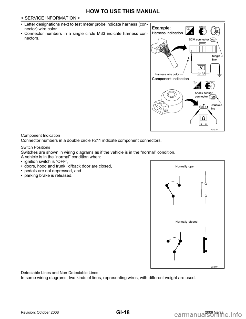
• Letter designations next to test meter probe indicate harness (con- nector) wire color.
• Connector numbers in a single circle M33 indicate harness con-
nectors.
Component Indication
Connector numbers in a double circle F211 indicate component connectors.
Switch Positions
Switches are shown in wiring diagrams as if the vehicle is in the “normal” condition.
A vehicle is in the “normal” condition when:
• ignition switch is “OFF”,
• doors, hood and trunk lid/back door are closed,
• pedals are not depressed, and
• parking brake is released.
Detectable Lines and Non-Detectable Lines
In some wiring diagrams, two kinds of lines, r epresenting wires, with different weight are used. AGI070
SGI860