2009 NISSAN LATIO trunk
[x] Cancel search: trunkPage 3377 of 4331

IP
N
O P
The following materials, not found in the kit, can also be used to repair squeaks and rattles.
UHMW (TEFLON) TAPE
Insulates where slight movement is present. Ideal for instrument panel applications.
SILICONE GREASE
Used in place of UHMW tape that will be visible or not fit.
Note: Will only last a few months.
SILICONE SPRAY
Use when grease cannot be applied.
DUCT TAPE
Use to eliminate movement.
CONFIRM THE REPAIR Confirm that the cause of a noise is repaired by test driving the vehicle. Operate the vehicle under the same
conditions as when the noise originally occurred. Refer to the notes on the Diagnostic Worksheet.
Generic Squeak and Rattle Troubleshooting INFOID:0000000004307245
Refer to Table of Contents for specific component removal and installation information.
INSTRUMENT PANEL Most incidents are caused by contact and movement between:
1. The cluster lid A and instrument panel
2. Acrylic lens and combination meter housing
3. Instrument panel to front pillar garnish
4. Instrument panel to windshield
5. Instrument panel mounting pins
6. Wiring harnesses behind the combination meter
7. A/C defroster duct and duct joint
These incidents can usually be located by tapping or moving the components to duplicate the noise or by
pressing on the components while driving to stop the noi se. Most of these incidents can be repaired by apply-
ing felt cloth tape or silicone spray (in hard to reach areas). Urethane pads can be used to insulate wiring har-
ness.
CAUTION:
Do not use silicone spray to isolate a squeak or ra ttle. If you saturate the area with silicone, you will
not be able to recheck the repair.
CENTER CONSOLE Components to pay attention to include:
1. Shifter assembly cover to finisher
2. A/C control unit and cluster lid C
3. Wiring harnesses behind audio and A/C control unit
The instrument panel repair and isolation pr ocedures also apply to the center console.
DOORS Pay attention to the:
1. Finisher and inner panel making a slapping noise
2. Inside handle escutcheon to door finisher
3. Wiring harnesses tapping
4. Door striker out of alignment causing a popping noise on starts and stops
Tapping or moving the components or pressing on them wh ile driving to duplicate the conditions can isolate
many of these incidents. You can usually insulate the ar eas with felt cloth tape or insulator foam blocks from
the NISSAN Squeak and Rattle Kit (J-43980) to repair the noise.
TRUNK Trunk noises are often caused by a loose jack or loose items put into the trunk by the owner.
In addition look for:
1. Trunk lid bumpers out of adjustment
2. Trunk lid striker out of adjustment
Page 3422 of 4331

LAN
N
O P
Engine status signal T R
Fuel consumption monitor signal T R
Malfunction indicator lamp signal T R
Wide open throttle position signal T R R
A/C switch signal R T
Blower fan motor switch signal R T
Buzzer output signal T R
T R
Day time running light request signal *3
T R
Door lock/unlock status signal T R
Door switch signal T R R R
Front wiper request signal T R
High beam request signal T R R
Horn chirp signal T R
Ignition switch signal T R
Low beam request signal T R
Position lights request signal T R R
Rear window defogger switch signal T R
Sleep/wake up signal R T
T R R R
Theft warning horn request signal T R
Tire pressure signal *4
T R
Trunk open/close status signal T R
Turn indicator signal T R
EPS operation signal R T
EPS warning lamp signal T R
Door lock/unlock/trunk open request signal R T
Hazard request signal R T
Ignition knob switch signal R T
KEY warning lamp signal T R
LOCK warning lamp signal T R
Panic alarm request signal R T
Fuel level sensor signal R T
Overdrive control switch signal T R R
P/N range signal T R
Stop lamp switch signal T R R
Vehicle speed signal R R R R T
R R R T R
R*5
T*5
ABS warning lamp signal R T
Brake warning lamp signal R T
A/T check indicator signal R T Signal name/Connecting unitECM
BCM EPS
I-KEY
M&AABS
TCM *1
TCM *2
IPDM-E
Page 3689 of 4331
LT
N
O P
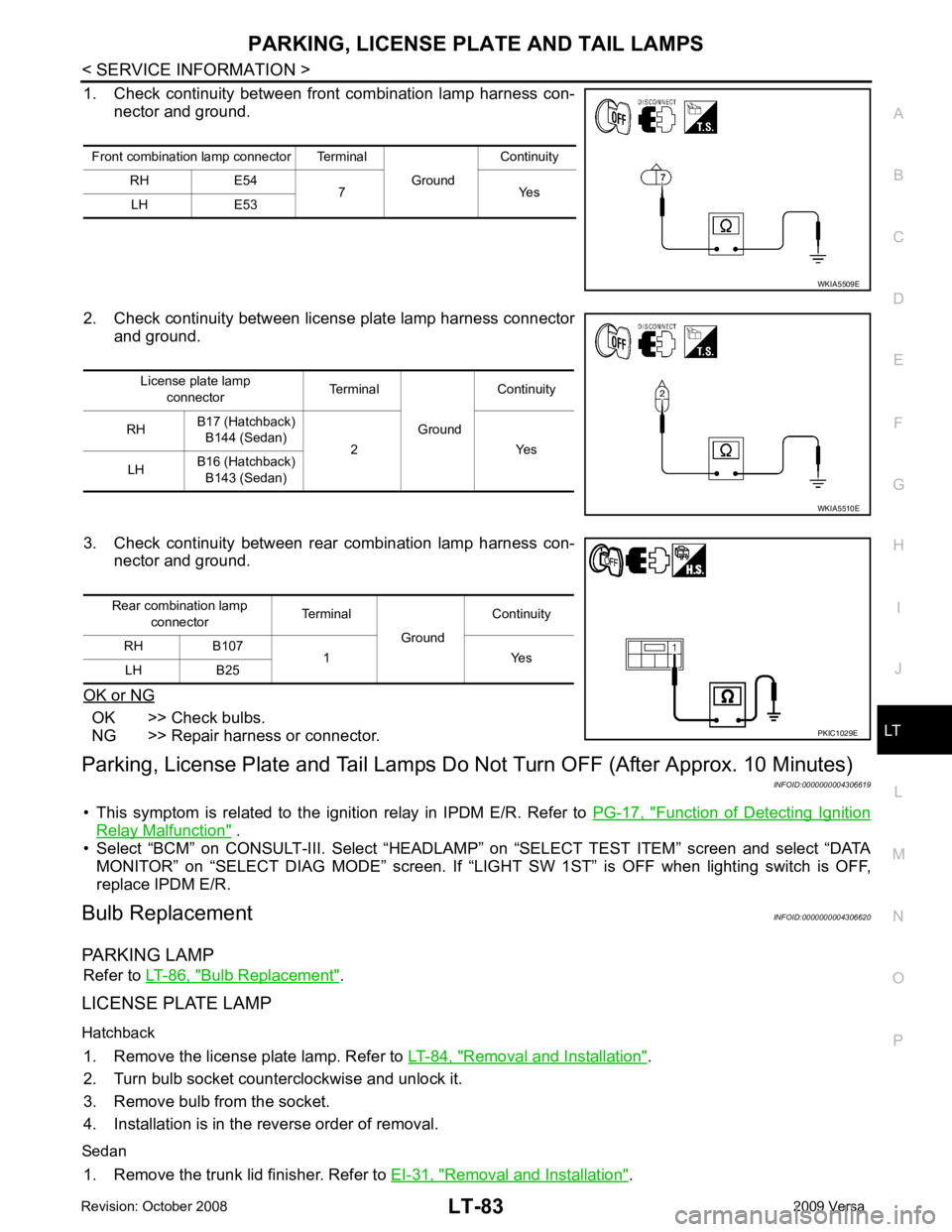
1. Check continuity between front
combination lamp harness con-
nector and ground.
2. Check continuity between license plate lamp harness connector and ground.
3. Check continuity between rear combination lamp harness con- nector and ground.
OK or NG OK >> Check bulbs.
NG >> Repair harness or connector.
Parking, License Plate and Tail Lamps Do Not Turn OFF (After Approx. 10 Minutes)
INFOID:0000000004306619
• This symptom is related to the ignition relay in IPDM E/R. Refer to PG-17, " Function of Detecting Ignition
Relay Malfunction " .
• Select “BCM” on CONSULT-III. Select “HEADLAM P” on “SELECT TEST ITEM” screen and select “DATA
MONITOR” on “SELECT DIAG MODE” sc reen. If “LIGHT SW 1ST” is OFF when lighting switch is OFF,
replace IPDM E/R.
Bulb Replacement INFOID:0000000004306620
PARKING LAMP Refer to LT-86, " Bulb Replacement " .
LICENSE PLATE LAMP
Hatchback 1. Remove the license plate lamp. Refer to LT-84, " Removal and Installation " .
2. Turn bulb socket counterclockwise and unlock it.
3. Remove bulb from the socket.
4. Installation is in the reverse order of removal.
Sedan 1. Remove the trunk lid finisher. Refer to EI-31, " Removal and Installation " .
Front combination lamp connector Terminal
GroundContinuity
RH E54 7 Yes
LH E53
Page 3692 of 4331
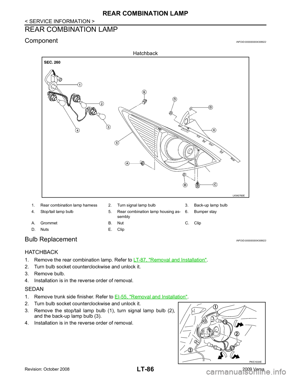
Removal and Installation " .
2. Turn bulb socket counterclockwise and unlock it.
3. Remove bulb.
4. Installation is in the reverse order of removal.
SEDAN
1. Remove trunk side finisher. Refer to EI-55, " Removal and Installation " .
2. Turn bulb socket counterclockwise and unlock it.
3. Remove the stop/tail lamp bulb (1), turn signal lamp bulb (2), and the back-up lamp bulb (3).
4. Installation is in the reverse order of removal.
Page 3693 of 4331
LT
N
O P
Removal and Installation
INFOID:0000000004306624
HATCHBACK
Removal 1. Remove rear combination lamp nuts.
2. Pull the rear combination lamp toward rear of the vehicle and remove from the vehicle.
3. Disconnect rear combination lamp connector, and remove rear combination lamp.
Installation Installation is in the reverse order of removal.
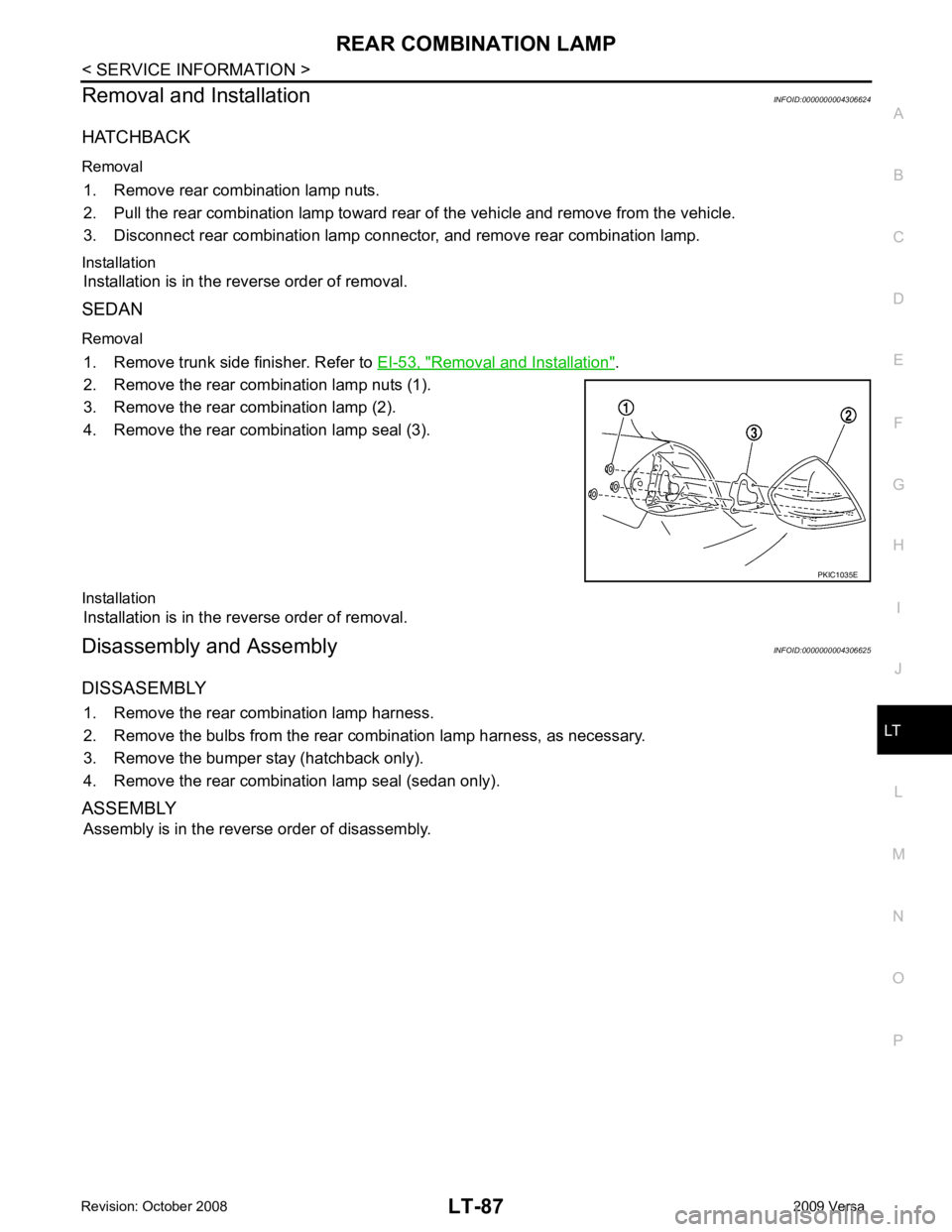
SEDAN
Removal 1. Remove trunk side finisher. Refer to EI-53, " Removal and Installation " .
2. Remove the rear combination lamp nuts (1).
3. Remove the rear combination lamp (2).
4. Remove the rear combination lamp seal (3).
Installation Installation is in the reverse order of removal.
Disassembly and Assembly INFOID:0000000004306625
DISSASEMBLY 1. Remove the rear combination lamp harness.
2. Remove the bulbs from the rear combination lamp harness, as necessary.
3. Remove the bumper stay (hatchback only).
4. Remove the rear combination lamp seal (sedan only).
ASSEMBLY Assembly is in the reverse order of disassembly.
Page 3695 of 4331
LT
N
O P
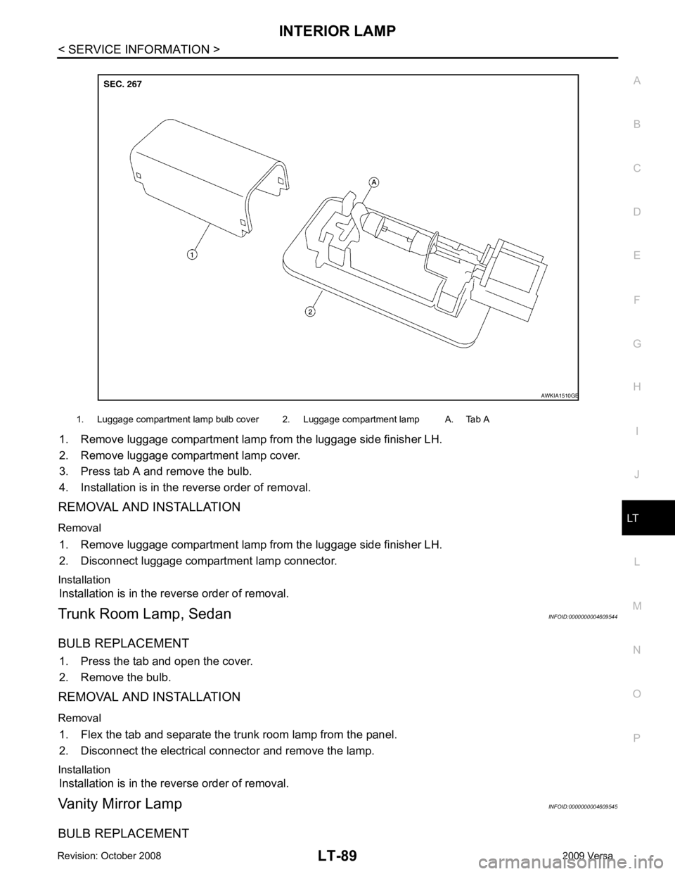
1. Remove luggage compartment lamp from the luggage side finisher LH.
2. Remove luggage compartment lamp cover.
3. Press tab A and remove the bulb.
4. Installation is in the reverse order of removal.
REMOVAL AND INSTALLATION
Removal 1. Remove luggage compartment lamp from the luggage side finisher LH.
2. Disconnect luggage compartment lamp connector.
Installation Installation is in the reverse order of removal.
Trunk Room Lamp, Sedan INFOID:0000000004609544
BULB REPLACEMENT 1. Press the tab and open the cover.
2. Remove the bulb.
REMOVAL AND INSTALLATION
Removal 1. Flex the tab and separate the trunk room lamp from the panel.
2. Disconnect the electrical connector and remove the lamp.
Installation Installation is in the reverse order of removal.
Vanity Mirror Lamp INFOID:0000000004609545
BULB REPLACEMENT 1. Luggage compartment lamp bulb cover 2. Luggage compartment lamp A. Tab A
Page 3697 of 4331
LT
N
O P
INTERIOR ROOM LAMP
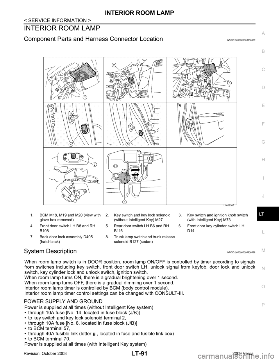
Component Parts and Har ness Connector Location INFOID:0000000004306628
System Description INFOID:0000000004306629
When room lamp switch is in DOOR position, room la mp ON/OFF is controlled by timer according to signals
from switches including key switch, front door switch LH, unlock signal from keyfob, door lock and unlock
switch, key cylinder lock and unlock switch, ignition switch.
When room lamp turns ON, there is a gradual brightening over 1 second.
When room lamp turns OFF, there is a gradual dimming over 1 second.
Interior room lamp timer is controlled by BCM (body control module).
Interior room lamp timer control settings can be changed with CONSULT-III.
POWER SUPPLY AND GROUND Power is supplied at all times (without Intelligent Key system)
• through 10A fuse [No. 14, located in fuse block (J/B)]
• to key switch and key lock solenoid terminal 2,
• through 10A fuse [No. 8, located in fuse block (J/B)]
• to BCM terminal 57,
• through 40A fusible link (letter g , located in fuse and fusible link box)
• to BCM terminal 70.
Power is supplied at all times (with Intelligent Key system) 1. BCM M18, M19 and M20 (view with
glove box removed) 2. Key switch and key lock solenoid
(without Intelligent Key) M27 3. Key switch and ignition knob switch
(with Intelligent Key) M73
4. Front door switch LH B8 and RH B108 5. Rear door switch LH B6 and RH
B116 6. Front door key cylinder switch LH
D14
7. Back door lock assembly D405 (hatchback) 8. Trunk lamp switch and trunk release
solenoid B127 (sedan)
Page 3707 of 4331
LT
N
O P
3. Perform the preliminary check. Refer to
LT-101, " Preliminary Check " .
4. Check symptom and repair or replace the cause of the malfunction.
5. Does the interior room lamp operate norma lly? If YES, GO TO 6. If NO, GO TO 4.
6. Inspection End
Preliminary Check INFOID:0000000004306634
CHECK POWER SUPPLY AND GROUND CIRCUIT FOR BCM Refer to BCS-15, " BCM Power Supply and Ground Circuit Inspection " .
CHECK POWER SUPPLY AND GROUND CIRCUIT FOR IPDM E/R Refer to LT-11, " Preliminary Check " .
CONSULT-III Function (BCM) INFOID:0000000004306635
Refer to LT-11, " CONSULT-III Function (BCM) " .
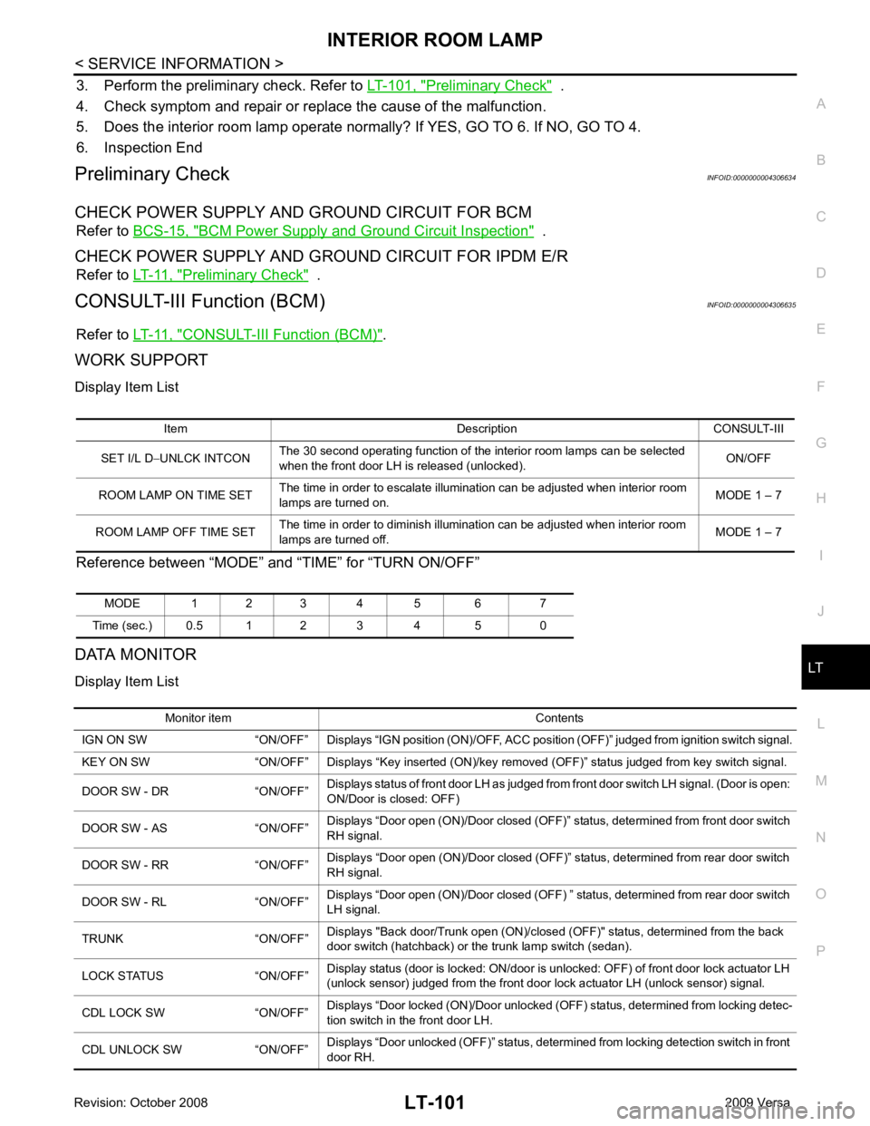
WORK SUPPORT
Display Item List
Reference between “MODE” and “TIME” for “TURN ON/OFF”
DATA MONITOR
Display Item List Item Description CONSULT-III
SET I/L D −UNLCK INTCON The 30 second operating function of the interior room lamps can be selected
when the front door LH is released (unlocked). ON/OFF
ROOM LAMP ON TIME SET The time in order to escalate illumination can be adjusted when interior room
lamps are turned on. MODE 1 – 7
ROOM LAMP OFF TIME SET The time in order to diminish illumination can be adjusted when interior room
lamps are turned off. MODE 1 – 7
MODE 1 2 3 4 5 6 7
Time (sec.) 0.5 1 2 3 4 5 0 Monitor item Contents
IGN ON SW “ON/OFF” Displays “IGN position (ON)/OFF, ACC position (OFF)” judged from ignition switch signal.
KEY ON SW “ON/OFF” Displays “Key inse rted (ON)/key removed (OFF)” status judged from key switch signal.
DOOR SW - DR “ON/OFF” Displays status of front door LH as judged from front door switch LH signal. (Door is open:
ON/Door is closed: OFF)
DOOR SW - AS “ON/OFF” Displays “Door open (ON)/Door closed (OFF)” status, determined from front door switch
RH signal.
DOOR SW - RR “ON/OFF” Displays “Door open (ON)/Door closed (OFF)” status, determined from rear door switch
RH signal.
DOOR SW - RL “ON/OFF” Displays “Door open (ON)/Door closed (OFF) ” status, determined from rear door switch
LH signal.
TRUNK “ON/OFF” Displays "Back door/Trunk open (ON)/closed (OFF)" status, determined from the back
door switch (hatchback) or the trunk lamp switch (sedan).
LOCK STATUS “ON/OFF” Display status (door is locked: ON/door is unlocked: OFF) of front door lock actuator LH
(unlock sensor) judged from the front door lock actuator LH (unlock sensor) signal.
CDL LOCK SW “ON/OFF” Displays “Door locked (ON)/Door unlocked (OFF) status, determined from locking detec-
tion switch in the front door LH.
CDL UNLOCK SW “ON/OFF” Displays “Door unlocked (OFF)” status, determined from locking detection switch in front
door RH.