2009 NISSAN LATIO check engine
[x] Cancel search: check enginePage 580 of 4331

BL
N
O P
Trouble Diagnosis Symptom Chart INFOID:0000000004305044
KEY WARNING LAMP (GREEN) ILLUMINATES NOTE: Monitor item Description
CONFIRM KEY FOB ID It can be checked whether Intelligent Key ID code is registered or not in this mode.
TAKE OUT FROM WINDOW
WARN Take away warning chime (from window) mode can be changed to operate (ON) or not operate
(OFF) with this mode. The operation mode will be changed when “CHANGE SETT” on CONSULT-
III screen is touched.
LOW BAT OF KEY FOB WARN Intelligent Key low battery warning mode can be changed to operate (ON) or not operate (OFF)
with this mode. The operation mode will be changed when “CHANGE SETT” on CONSULT-III
screen is touched.
ANSWER BACK FUNCTION Buzzer reminder function mode by Intelligent button can be changed to operate (ON) or not oper-
ate (OFF) with this mode. The operation mode will be changed when “CHANGE SETT” on CON-
SULT-III screen is touched.
SELECTIVE UNLOCK FUNC-
TION Selective unlock function mode can be changed to operate (ON) or not operate (OFF) with this
mode. The operation mode will be changed when “CHANGE SETT” on CONSULT-III screen is
touched.
ANTI KEY LOCK IN FUNCTION Key reminder function mode can be changed to operate (ON) or not operate (OFF) with this mode.
The operation mode will be changed when “CHANGE SETT” on CONSULT-III screen is touched.
HORN WITH KEYLESS LOCK Horn reminder function mode by Intelligent Key remote control button can be changed to operate
(ON) or not operate (OFF) with this mode. The operation mode will be changed when “CHANGE
SETT” on CONSULT-III screen is touched.
HAZARD ANSWER BACK Hazard reminder function mode can be selected from the following with this mode. The operation
mode will be changed when “CHANGE SE TT” on CONSULT-III screen is touched.
• LOCK ONLY: Door lock operation only
• UNLOCK ONLY: Door unlock operation only
• LOCK/UNLOCK: Lock/Unlock operation
• OFF: Non-operation
ANSWER BACK WITH I-KEY
LOCK Buzzer reminder function (lock operation) mode by door request switch (driver side, passenger
side and back door side) can be selected from the following with this mode. The operation mode
will be changed when “ CHANGE SETT” on CONSULT- III screen is touched.
• BUZZER: Sound buzzer
• OFF: Non-operation
ANSWER BACK WITH I-KEY UN-
LOCK Buzzer reminder function (unlock operation) mode by door request switch can be changed to op-
erate (ON) or not operate (OFF) with this mode.
AUTO RELOCK TIMER Auto door lock timer mode can select the following with this mode.
• 1 minute
• OFF: Non-operation
PANIC ALARM DELAY Panic alarm button's pressing time on Intelligent Key remote control button can be selected from
the following with this mode. The operation mode will be changed when “CHANGE SETT” on
CONSULT-III screen is touched.
• 0.5 second
• 1.5 second
• OFF: Non-operation
P/W DOWN DELAY Unlock button's pressing time on Intelligent Key remote control button can be selected from the
following with this mode. The operation mode will be changed when “CHANGE SETT” on CON-
SULT-III screen is touched.
• 3 seconds
• 5 seconds
• OFF: Non-operation
ENGINE START BY I-KEY Engine start function mode can be changed to operate (ON) or not operate (OFF) with this mode.
The operation mode will be changed when “CHANGE SETT” on CONSULT-III screen is touched.
LOCK/UNLOCK BY I-KEY Door lock/unlock function by door request switch (driver side, passenger side and back door side)
mode can be changed to operate (ON) or not operate (OFF) with this mode. The operation mode
will be changed when “ CHANGE SETT” on CONSULT- III screen is touched.
Page 581 of 4331
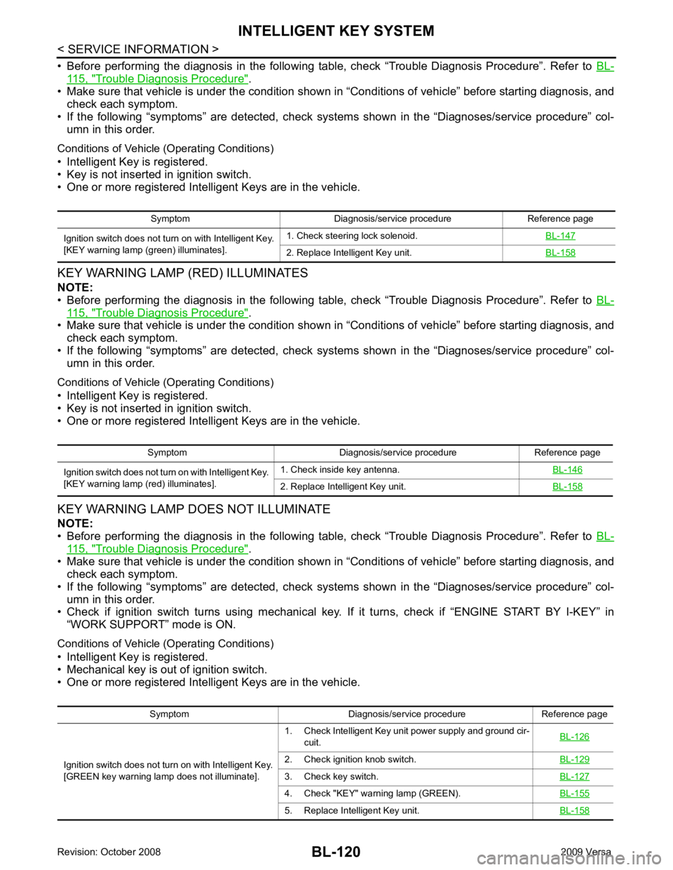
115, " Trouble Diagnosis Procedure " .
• Make sure that vehicle is under the condition shown in “Conditions of vehicle” before starting diagnosis, and
check each symptom.
• If the following “symptoms” are detected, check systems shown in the “Diagnoses/service procedure” col- umn in this order.
Conditions of Vehicle (Operating Conditions)
• Intelligent Key is registered.
• Key is not inserted in ignition switch.
• One or more registered Intelligent Keys are in the vehicle.
KEY WARNING LAMP (RED) ILLUMINATES
NOTE:
• Before performing the diagnosis in the following table, check “Trouble Diagnosis Procedure”. Refer to BL-115, " Trouble Diagnosis Procedure " .
• Make sure that vehicle is under the condition shown in “Conditions of vehicle” before starting diagnosis, and
check each symptom.
• If the following “symptoms” are detected, check systems shown in the “Diagnoses/service procedure” col- umn in this order.
Conditions of Vehicle (Operating Conditions)
• Intelligent Key is registered.
• Key is not inserted in ignition switch.
• One or more registered Intelligent Keys are in the vehicle.
KEY WARNING LAMP DOES NOT ILLUMINATE
NOTE:
• Before performing the diagnosis in the following table, check “Trouble Diagnosis Procedure”. Refer to BL-115, " Trouble Diagnosis Procedure " .
• Make sure that vehicle is under the condition shown in “Conditions of vehicle” before starting diagnosis, and
check each symptom.
• If the following “symptoms” are detected, check systems shown in the “Diagnoses/service procedure” col- umn in this order.
• Check if ignition switch turns using mechanical key. If it turns, check if “ENGINE START BY I-KEY” in
“WORK SUPPORT” mode is ON.
Conditions of Vehicle (Operating Conditions)
• Intelligent Key is registered.
• Mechanical key is out of ignition switch.
• One or more registered Intelligent Keys are in the vehicle. Symptom Diagnosis/service procedure Reference page
Ignition switch does not turn on with Intelligent Key.
[KEY warning lamp (g reen) illuminates]. 1. Check steering lock solenoid.
BL-147 2. Replace Intelligent Key unit.
BL-158Symptom Diagnosis/service procedure Reference page
Ignition switch does not turn on with Intelligent Key.
[KEY warning lamp (re d) illuminates]. 1. Check inside key antenna.
BL-146 2. Replace Intelligent Key unit.
BL-158Symptom Diagnosis/service procedure Reference page
Ignition switch does not turn on with Intelligent Key.
[GREEN key warning lamp does not illuminate]. 1. Check Intelligent Key unit power supply and ground cir-
cuit. BL-126 2. Check ignition knob switch.
BL-129 3. Check key switch.
BL-127 4. Check "KEY" warn
ing lamp (GREEN). BL-155 5. Replace Intelligent Key unit.
BL-158
Page 582 of 4331
BL
N
O P
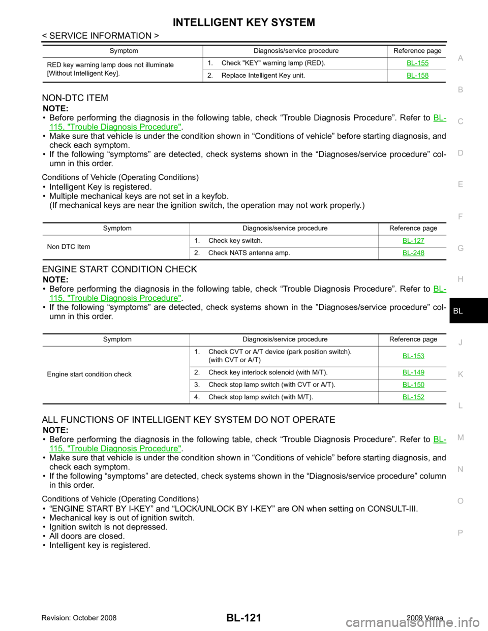
NON-DTC ITEM
NOTE:
• Before performing the diagnosis in the following table, check “Trouble Diagnosis Procedure”. Refer to BL-115, " Trouble Diagnosis Procedure " .
• Make sure that vehicle is under the condition shown in “Conditions of vehicle” before starting diagnosis, and
check each symptom.
• If the following “symptoms” are detected, check syst ems shown in the “Diagnoses/service procedure” col-
umn in this order.
Conditions of Vehicle (Operating Conditions) • Intelligent Key is registered.
• Multiple mechanical keys are not set in a keyfob. (If mechanical keys are near the ignition switch, the operation may not work properly.)
ENGINE START CONDITION CHECK NOTE:
• Before performing the diagnosis in the following table, check “Trouble Diagnosis Procedure”. Refer to BL-115, " Trouble Diagnosis Procedure " .
• If the following “symptoms” are detected, check syst ems shown in the ”Diagnoses/service procedure” col-
umn in this order.
ALL FUNCTIONS OF INTELLIGENT KEY SYSTEM DO NOT OPERATE
NOTE:
• Before performing the diagnosis in the following table, check “Trouble Diagnosis Procedure”. Refer to BL-115, " Trouble Diagnosis Procedure " .
• Make sure that vehicle is under the condition shown in “Conditions of vehicle” before starting diagnosis, and
check each symptom.
• If the following “symptoms” are detected, check syst ems shown in the “Diagnosis/service procedure” column
in this order.
Conditions of Vehicle (Operating Conditions) • “ENGINE START BY I-KEY” and “LOCK/UNLOCK BY I-KEY” are ON when setting on CONSULT-III.
• Mechanical key is out of ignition switch.
• Ignition switch is not depressed.
• All doors are closed.
• Intelligent key is registered. RED key warning lamp does not illuminate
[Without Intelligent Key]. 1. Check "KEY" warning lamp (RED).
BL-155 2. Replace Intelligent Key unit.
BL-158Symptom Diagnosis/service procedure Reference page
Symptom Diagnosis/service procedure Reference page
Non DTC Item 1. Check key switch.
BL-1272. Check NATS antenna amp.
BL-248Symptom Diagnosis/service procedure Reference page
Engine start condition check 1. Check CVT or A/T device (park position switch).
(with CVT or A/T) BL-153 2. Check key interlock solenoid (with M/T).
BL-1493. Check stop lamp switch (with CVT or A/T).
BL-1504. Check stop lamp switch (with M/T).
BL-152
Page 718 of 4331
BL
N
O P
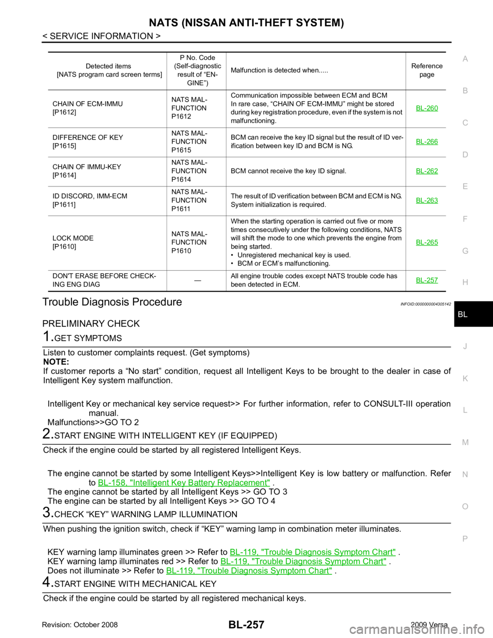
Trouble Diagnosis Procedure
INFOID:0000000004305142
PRELIMINARY CHECK Intelligent Key Battery Replacement " .
The engine cannot be started by all Intelligent Keys >> GO TO 3
The engine can be started by all Intelligent Keys >> GO TO 4 Trouble Diagnosis Symptom Chart " .
KEY warning lamp illuminates red >> Refer to BL-119, " Trouble Diagnosis Symptom Chart " .
Does not illuminate >> Refer to BL-119, " Trouble Diagnosis Symptom Chart " .DIFFERENCE OF KEY
[P1615] NATS MAL-
FUNCTION
P1615 BCM can receive the key ID signal but the result of ID ver-
ification between key ID and BCM is NG. BL-266CHAIN OF IMMU-KEY
[P1614] NATS MAL-
FUNCTION
P1614 BCM cannot receive the key ID signal.
BL-262ID DISCORD, IMM-ECM
[P1611] NATS MAL-
FUNCTION
P1611 The result of ID verification between BCM and ECM is NG.
System initialization is required. BL-263LOCK MODE
[P1610] NATS MAL-
FUNCTION
P1610 When the starting operation is carried out five or more
times consecutively under the following conditions, NATS
will shift the mode to one which prevents the engine from
being started.
• Unregistered mechanical key is used.
• BCM or ECM’s malfunctioning. BL-265DON'T ERASE BEFORE CHECK-
ING ENG DIAG —All engine trouble codes except NATS trouble code has
been detected in ECM. BL-257
Page 721 of 4331

CAN Com-
munication Inspection Using CONSULT-III (Self-Diagnosis) " .
SYMPTOM
Displayed “SELF-DIAG
RESULTS” on CON- SULT-III screen. DIAGNOSTIC PROCE-
DURE
(Reference page) SYSTEM
(Malfunctioning part or mode)
• Security indicator lighting up*
• Engine cannot be started CHAIN OF ECM-IMMU
[P1612] PROCEDURE 1
(BL-260 )
In rare case, “CHAIN OF ECM-IMMU” might be stored
during key registration procedure, even if the system is
not malfunctioning.
Open circuit in battery voltage line of BCM circuit
Open circuit in ignition line of BCM circuit
Open circuit in ground line of BCM circuit
Open or short circuit between BCM and ECM commu-
nication line
ECM
BCM
DIFFERENCE OF KEY [P1615] PROCEDURE 6
(BL-266 )
Unregistered ignition key is used.
BCM is malfunctioning.
CHAIN OF IMMU-KEY [P1614] PROCEDURE 2
(BL-262 )
Malfunction of key ID chip
Communication line between ANT/ AMP and BCM:
Open circuit or short circuit of battery voltage line or
ground line
Open circuit in power source line of ANT/ AMP circuit
Open circuit in ground line of ANT/ AMP circuit
NATS antenna amp.
BCM
ID DISCORD, IMM- ECM
[P1611] PROCEDURE 3
(BL-263 )
System initialization has not yet been completed.
ECM
LOCK MODE [P1610] PROCEDURE 5
(BL-265 )
When the starting operation is carried out five or more
times consecutively under the following conditions,
NATS will shift the mode to one which prevents the en-
gine from being started.
• Unregistered ignition key is used.
• BCM or ECM’s malfunctioning.
Security indicator
lighting up* DON'T ERASE BE-
FORE CHECKING ENG DIAG WORK FLOW
(BL-257 )
Engine trouble data and NATS trouble data have been
detected in ECM SYMPTOM
DIAGNOSTIC PROCEDURE
(Reference page) SYSTEM
(Malfunctioning part or mode)
Security indicator does not light up*. PROCEDURE 4
(BL-264 )
Security indictor.
Open circuit between Fuse and BCM
BCM
Page 723 of 4331
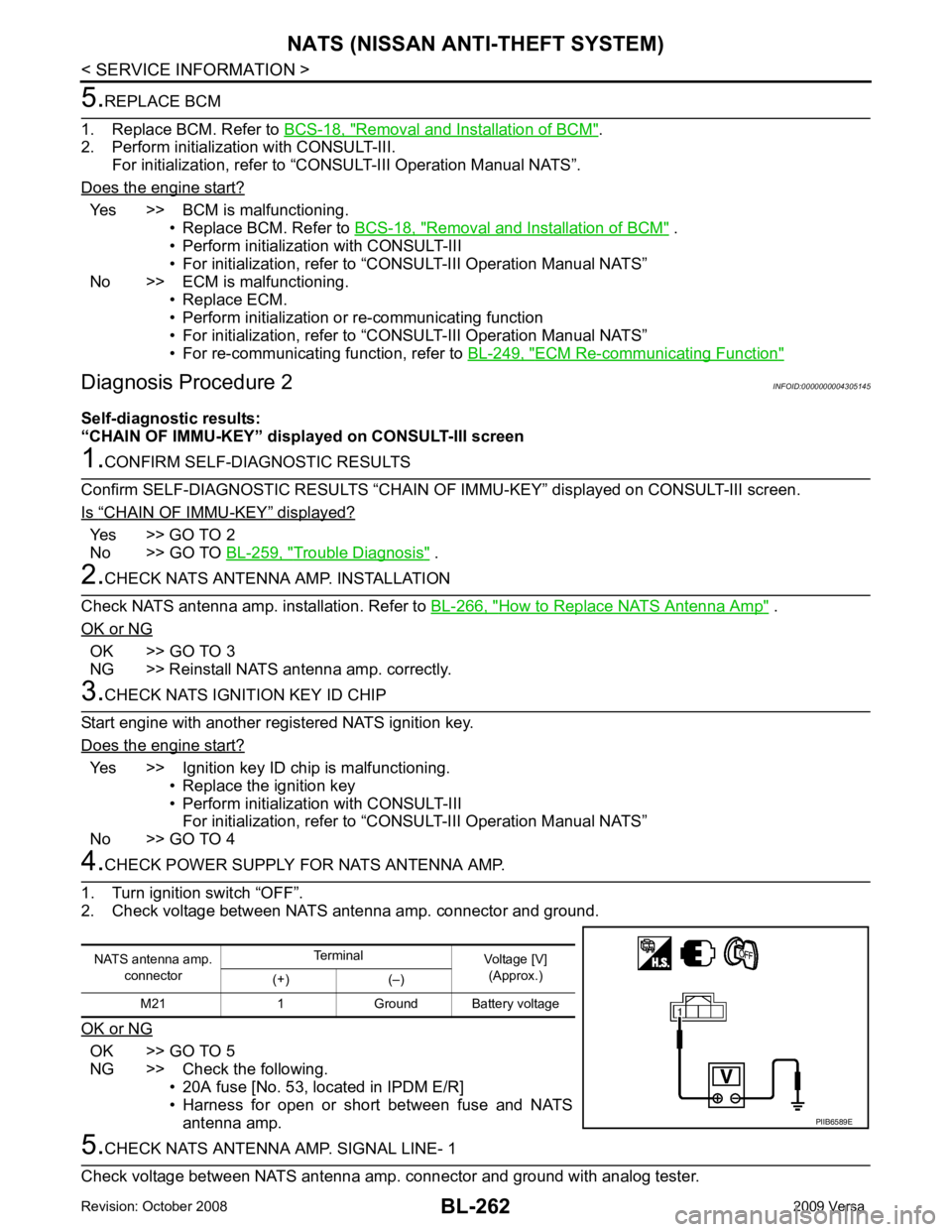
Removal and Installation of BCM " .
2. Perform initialization with CONSULT-III.
For initialization, refer to “CONSULT-III Operation Manual NATS”.
Does the engine start? Yes >> BCM is malfunctioning.
• Replace BCM. Refer to BCS-18, " Removal and Installation of BCM " .
• Perform initialization with CONSULT-III
• For initialization, refer to “CONSULT-III Operation Manual NATS”
No >> ECM is malfunctioning. • Replace ECM.
• Perform initialization or re-communicating function
• For initialization, refer to “CONSULT-III Operation Manual NATS”
• For re-communicating function, refer to BL-249, " ECM Re-communicating Function "
“ CHAIN OF IMMU-KEY ” displayed?
Yes >> GO TO 2
No >> GO TO BL-259, " Trouble Diagnosis " .
How to Replace NATS Antenna Amp " .
OK or NG OK >> GO TO 3
NG >> Reinstall NATS antenna amp. correctly. Yes >> Ignition key ID chip is malfunctioning.
• Replace the ignition key
• Perform initialization with CONSULT-III For initialization, refer to “CONSULT-III Operation Manual NATS”
No >> GO TO 4 OK >> GO TO 5
NG >> Check the following. • 20A fuse [No. 53, located in IPDM E/R]
• Harness for open or short between fuse and NATS
antenna amp.
Page 725 of 4331
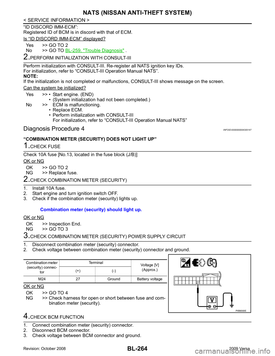
“ ID DISCORD IMM-ECM ” displayed?
Yes >> GO TO 2
No >> GO TO BL-259, " Trouble Diagnosis " .
Yes >> • Start engine. (END)
• (System initialization had not been completed.)
No >> ECM is malfunctioning. • Replace ECM.
• Perform initialization with CONSULT-III For initialization, refer to “CONSULT-III Operation Manual NATS”
Diagnosis Procedure 4 INFOID:0000000004305147
“COMBINATION METER (SECURITY) DOES NOT LIGHT UP” OK >> GO TO 2
NG >> Replace fuse. OK >> Inspection End.
NG >> GO TO 3 OK >> GO TO 4
NG >> Check harness for open or short between fuse and com- bination meter (security).
Page 807 of 4331
BR
N
O P
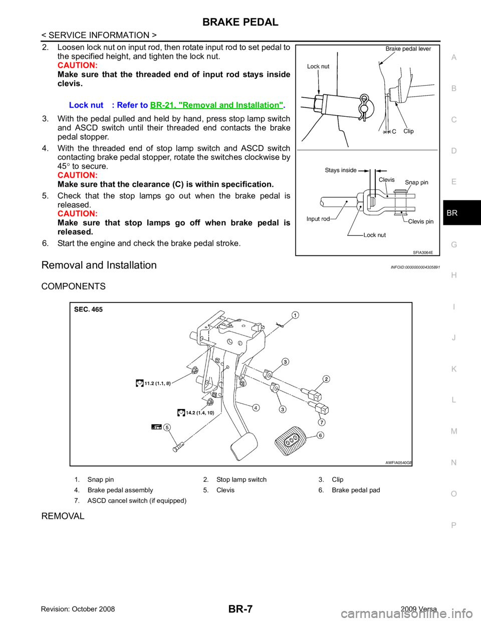
2. Loosen lock nut on input rod, then rotate input rod to set pedal to
the specified height, and tighten the lock nut.
CAUTION:
Make sure that the threaded end of input rod stays inside
clevis.
3. With the pedal pulled and held by hand, press stop lamp switch and ASCD switch until their threaded end contacts the brake
pedal stopper.
4. With the threaded end of stop lamp switch and ASCD switch contacting brake pedal stopper, rotate the switches clockwise by
45 ° to secure.
CAUTION:
Make sure that the clearance (C) is within specification.
5. Check that the stop lamps go out when the brake pedal is released.
CAUTION:
Make sure that stop lamps go off when brake pedal is
released.
6. Start the engine and check the brake pedal stroke.
Removal and Installation INFOID:0000000004305891
COMPONENTS
REMOVAL Lock nut : Refer to
BR-21, " Removal and Installation " .