2009 NISSAN LATIO ECU
[x] Cancel search: ECUPage 861 of 4331
BRC
N
O P
Note 1: If wheel sens
or 2 for each wheel is indicated, check ABS actuator and electric unit (control unit) power supply voltage in addition
to wheel sensor circuit check.
Note 2: If multiple malfunctions are detected including CAN communication line [U1000], perform diagnosis for CAN communication line
first.
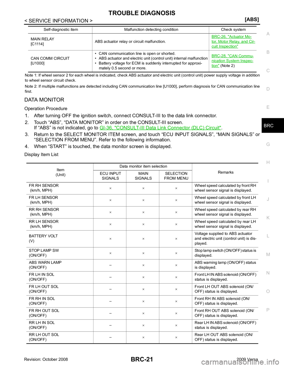
DATA MONITOR
Operation Procedure 1. After turning OFF the ignition switch, c onnect CONSULT-III to the data link connector.
2. Touch “ABS”, “DATA MONITOR” in order on the CONSULT-III screen. If “ABS” is not indicated, go to GI-36, " CONSULT-III Data Link Connector (DLC) Circuit " .
3. Return to the SELECT MONITOR ITEM screen, and touch “ECU INPUT SIGNALS”, “MAIN SIGNALS” or
“SELECTION FROM MENU”. Refer to the following information.
4. When “START” is touched, the data monitor screen is displayed.
Display Item List MAIN RELAY
[C1114] ABS actuator relay or circuit malfunction. BRC-26, " Actuator Mo-
tor, Motor Relay, and Cir-
cuit Inspection "
CAN COMM CIRCUIT
[U1000] • CAN communication line is open or shorted.
• ABS actuator and electric unit (control unit) internal malfunction
• Battery voltage for ECM is suddenly interrupted for approxi-
mately 0.5 second or more. BRC-28, " CAN Commu-
nication System Inspec-
tion " (Note 2)
Self-diagnostic item Malfunction detecting condition Check system Item
(Unit) Data monitor item selection
Remarks
ECU INPUT
SIGNALS MAIN
SIGNALS SELECTION
FROM MENU
FR RH SENSOR
(km/h, MPH) × × × Wheel speed calculated by front RH
wheel sensor signal is displayed.
FR LH SENSOR
(km/h, MPH) × × ×
Wheel speed calculated by front LH
wheel sensor signal is displayed.
RR RH SENSOR
(km/h, MPH) × × × Wheel speed calculated by rear RH
wheel sensor signal is displayed.
RR LH SENSOR
(km/h, MPH) × × × Wheel speed calculated by rear LH
wheel sensor signal is displayed.
BATTERY VOLT
(V) × × × Voltage supplied to ABS actuator
and electric unit (control unit) is dis-
played.
STOP LAMP SW
(ON/OFF) × × × Stop lamp switch (ON/OFF) status is
displayed.
ABS WARN LAMP
(ON/OFF) –
× × ABS warning lamp (ON/OFF) status
is displayed.
FR LH IN SOL
(ON/OFF) –
× × Front LH IN ABS solenoid (ON/OFF)
status is displayed.
FR LH OUT SOL
(ON/OFF) –
× × Front LH OUT ABS solenoid (ON/
OFF) status is displayed.
FR RH IN SOL
(ON/OFF) –
× × Front RH IN ABS solenoid (ON/
OFF) status is displayed.
FR RH OUT SOL
(ON/OFF) –
× × Front RH OUT ABS solenoid (ON/
OFF) status is displayed.
RR LH IN SOL
(ON/OFF) –
× × Rear LH IN ABS solenoid (ON/OFF)
status is displayed.
RR LH OUT SOL
(ON/OFF) –
× × Rear LH OUT ABS solenoid (ON/
OFF) status is displayed.
Page 862 of 4331
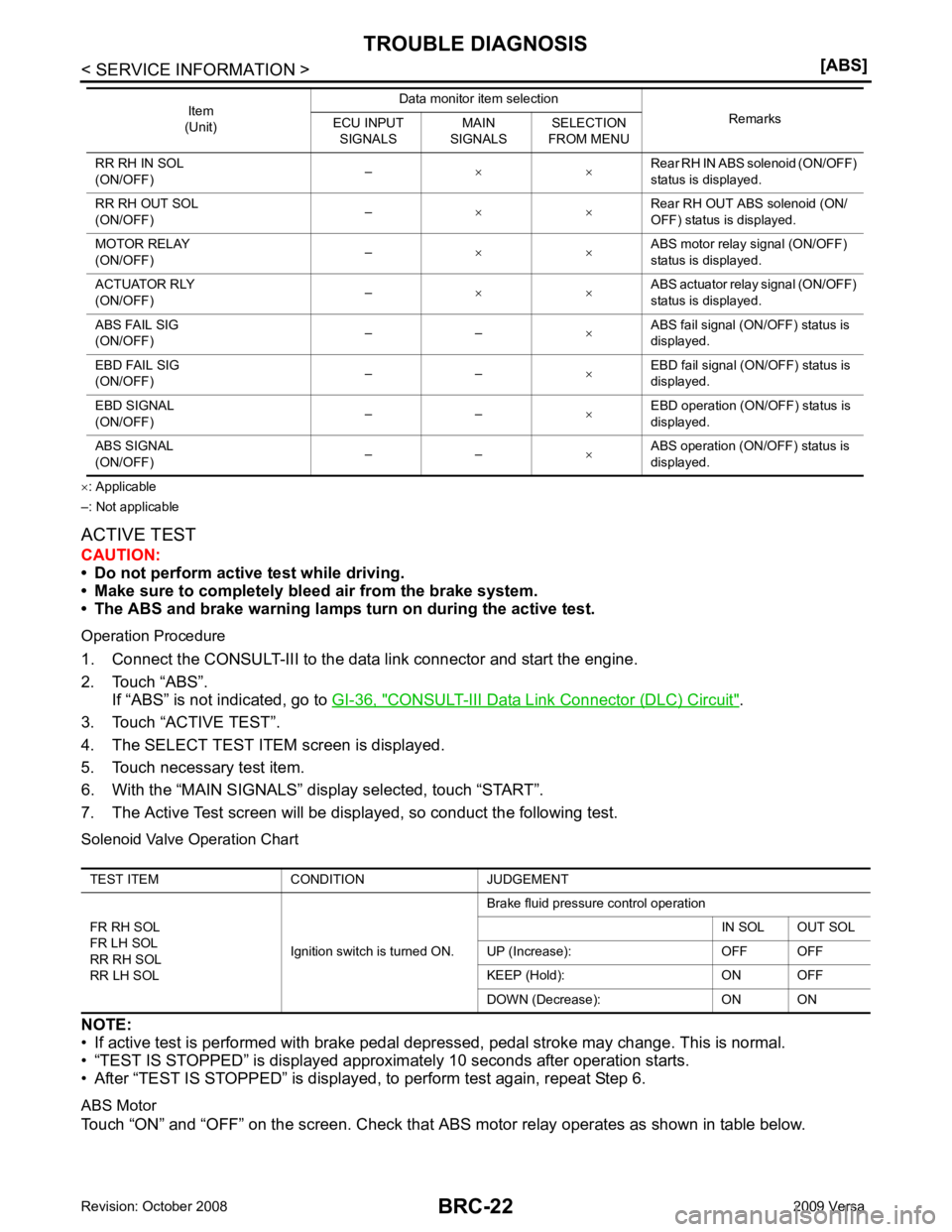
CONSULT-III Data Link Connector (DLC) Circuit " .
3. Touch “ACTIVE TEST”.
4. The SELECT TEST ITEM screen is displayed.
5. Touch necessary test item.
6. With the “MAIN SIGNALS” display selected, touch “START”.
7. The Active Test screen will be displayed, so conduct the following test.
Solenoid Valve Operation Chart
NOTE:
• If active test is performed with brake pedal depr essed, pedal stroke may change. This is normal.
• “TEST IS STOPPED” is displayed approximately 10 seconds after operation starts.
• After “TEST IS STOPPED” is displayed, to perform test again, repeat Step 6.
ABS Motor
Touch “ON” and “OFF” on the screen. Check that ABS motor relay operates as shown in table below.
RR RH IN SOL
(ON/OFF) –
× × Rear RH IN ABS solenoid (ON/OFF)
status is displayed.
RR RH OUT SOL
(ON/OFF) –
× × Rear RH OUT ABS solenoid (ON/
OFF) status is displayed.
MOTOR RELAY
(ON/OFF) –
× × ABS motor relay signal (ON/OFF)
status is displayed.
ACTUATOR RLY
(ON/OFF) –
× × ABS actuator relay signal (ON/OFF)
status is displayed.
ABS FAIL SIG
(ON/OFF) – –
×ABS fail signal (ON/OFF) status is
displayed.
EBD FAIL SIG
(ON/OFF) – –
×EBD fail signal (ON/OFF) status is
displayed.
EBD SIGNAL
(ON/OFF) – –
×EBD operation (ON/OFF) status is
displayed.
ABS SIGNAL
(ON/OFF) – –
×ABS operation (ON/OFF) status is
displayed.
Item
(Unit) Data monitor item selection
Remarks
ECU INPUT
SIGNALS MAIN
SIGNALS SELECTION
FROM MENU TEST ITEM CONDITION JUDGEMENT
FR RH SOL
FR LH SOL
RR RH SOL
RR LH SOL Ignition switch is turned ON.Brake fluid pressure control operation
IN SOL OUT SOL
UP (Increase): OFF OFF
KEEP (Hold): ON OFF
DOWN (Decrease): ON ON
Page 876 of 4331

Bleeding Brake System " .
CAUTION:
After installing harness connector in the ABS actuato r and electric unit (control unit), make sure the
connector is securely locked.
Page 886 of 4331
CL-10< SERVICE INFORMATION >
CLUTCH MASTER CYLINDER
CLUTCH MASTER CYLINDER
Removal and Installation INFOID:0000000004305171
REMOVAL
1. Remove the battery, battery tray and brackets. Refer to SC-5 .
2. Remove the air cleaner and air duct. Refer to EM-26, " Removal and Installation " (HR16DE models),
EM-139, " Removal and Installation " (MR18DE models).
3. Use one of the following methods to remove hose from master cylinder. • Drain clutch fluid from reservoir tank and remove hose.
• Remove hose from master cylinder. Immediately plug hose and reservoir tank to prevent clutch fluid
from dripping.
CAUTION:
Do not spill clutch fluid onto painted surfaces. If it spills, wi pe up immediately and wash the
affected area with water.
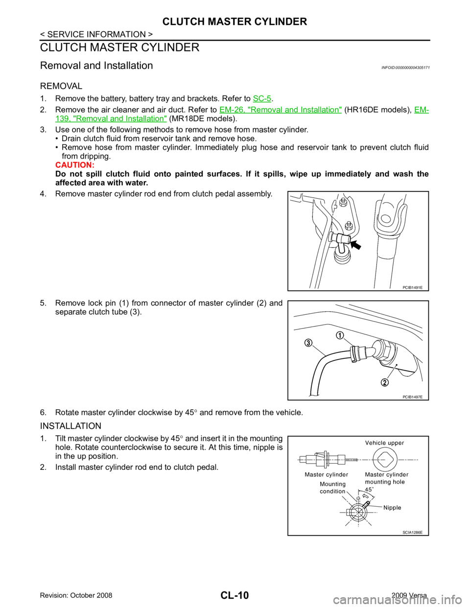
4. Remove master cylinder rod end from clutch pedal assembly.
5. Remove lock pin (1) from connector of master cylinder (2) and separate clutch tube (3).
6. Rotate master cylinder clockwise by 45 ° and remove from the vehicle.
INSTALLATION
1. Tilt master cylinder clockwise by 45 ° and insert it in the mounting
hole. Rotate counterclockwise to secure it. At this time, nipple is
in the up position.
2. Install master cylinder rod end to clutch pedal. PCIB1491E
PCIB1497E
SCIA1286E
Page 961 of 4331
CVT
N
O P
CVT FLUID
Checking CVT Fluid INFOID:0000000004666862
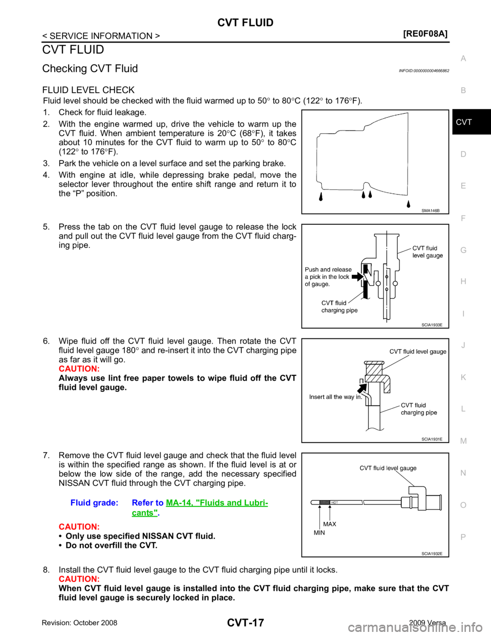
FLUID LEVEL CHECK Fluid level should be checked with the fluid warmed up to 50 ° to 80 °C (122 ° to 176 °F).
1. Check for fluid leakage.
2. With the engine warmed up, drive the vehicle to warm up the CVT fluid. When ambient temperature is 20 °C (68 °F), it takes
about 10 minutes for the CVT fluid to warm up to 50 ° to 80 °C
(122 ° to 176 °F).
3. Park the vehicle on a level surface and set the parking brake.
4. With engine at idle, while depressing brake pedal, move the selector lever throughout the entire shift range and return it to
the “P” position.
5. Press the tab on the CVT fluid level gauge to release the lock and pull out the CVT fluid level gauge from the CVT fluid charg-
ing pipe.
6. Wipe fluid off the CVT fluid level gauge. Then rotate the CVT fluid level gauge 180 ° and re-insert it into the CVT charging pipe
as far as it will go.
CAUTION:
Always use lint free paper towels to wipe fluid off the CVT
fluid level gauge.
7. Remove the CVT fluid level gauge and check that the fluid level is within the specified range as shown. If the fluid level is at or
below the low side of the range, add the necessary specified
NISSAN CVT fluid through the CVT charging pipe.
CAUTION:
• Only use specified NISSAN CVT fluid.
• Do not overfill the CVT.
8. Install the CVT fluid level gauge to the CVT fluid charging pipe until it locks. CAUTION:
When CVT fluid level gauge is installed into the CVT fluid charging pipe, make sure that the CVT
fluid level gauge is securely locked in place. Fluids and Lubri-
cants " .
Page 985 of 4331
![NISSAN LATIO 2009 Service Repair Manual TROUBLE DIAGNOSIS
CVT-41
< SERVICE INFORMATION >
[RE0F08A] D
E
F
G H
I
J
K L
M A
B CVT
N
O P
• Inspect for fluid leakage and check the fluid level. Refer to
CVT-17, " Checking CVT Fluid " .
Fluid NISSAN LATIO 2009 Service Repair Manual TROUBLE DIAGNOSIS
CVT-41
< SERVICE INFORMATION >
[RE0F08A] D
E
F
G H
I
J
K L
M A
B CVT
N
O P
• Inspect for fluid leakage and check the fluid level. Refer to
CVT-17, " Checking CVT Fluid " .
Fluid](/manual-img/5/57359/w960_57359-984.png)
TROUBLE DIAGNOSIS
CVT-41
< SERVICE INFORMATION >
[RE0F08A] D
E
F
G H
I
J
K L
M A
B CVT
N
O P
• Inspect for fluid leakage and check the fluid level. Refer to
CVT-17, " Checking CVT Fluid " .
Fluid Condition Check Inspect the fluid condition.
STALL TEST
Stall Test Procedure 1. Inspect the amount of engine oil. Replenish the engine oil if necessary.
2. Drive for about 10 minutes to warm up the vehicle so that the CVT fluid temperature is 50 to 80 °C (122 to 176 °F). Inspect the
amount of CVT fluid. Replenish if necessary.
3. Securely engage the parking brake so that the tires do not turn.
4. Install a tachometer where it can be seen by driver during test. •It is good practice to mark the point of specified engine
rpm on indicator.
5. Start engine, apply foot brake, and place selector lever in “D” position.Fluid status Conceivable cause Required operation
Varnished (viscous
varnish state) Clutch, brake
scorched Replace the CVT fluid and check the
CVT main unit and the vehicle for
malfunctions (wire harnesses, cool-
er pipes, etc.)
Milky white or
cloudy Water in the fluidReplace the CVT fluid and check for
places where water is getting in.
Large amount of
metal powder mixed
in Unusual wear of
sliding parts within
CVT Replace the CVT fluid and check for
improper operation of the CVT. SAT638A
SAT647B
SAT513G
SAT775B
Page 987 of 4331
CVT
N
O P
The CVT fluid temperature rises in the range of 50 - 80
°C (122 - 176 °F) during 10 minutes of driving.
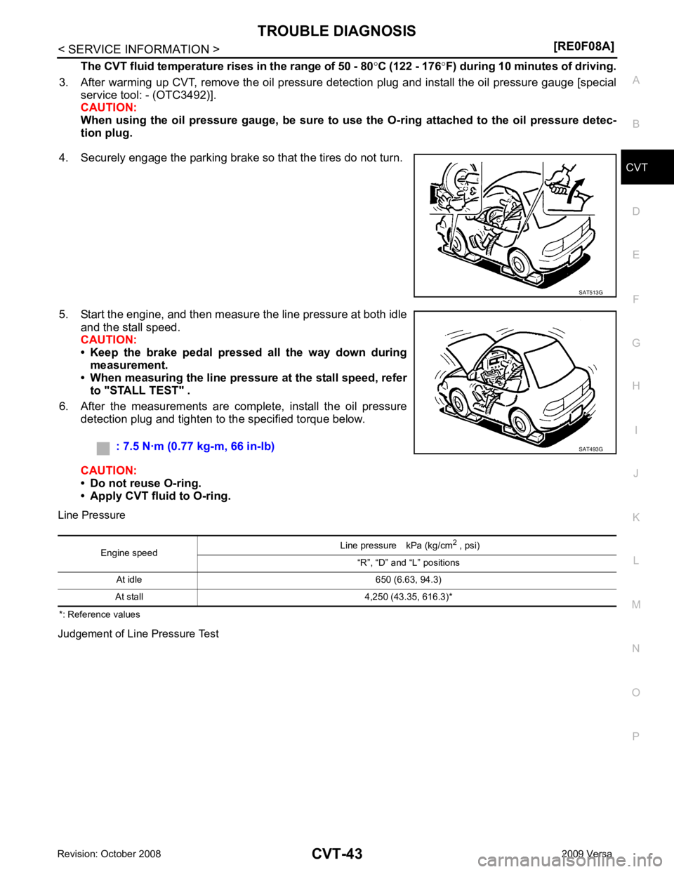
3. After warming up CVT, remove the oil pressure detection plug and install the oil pressure gauge [special service tool: - (OTC3492)].
CAUTION:
When using the oil pressure gauge, be sure to use the O-ring attached to the oil pressure detec-
tion plug.
4. Securely engage the parking brake so that the tires do not turn.
5. Start the engine, and then measure the line pressure at both idle and the stall speed.
CAUTION:
• Keep the brake pedal pressed all the way down during
measurement.
• When measuring the line pressure at the stall speed, refer
to "STALL TEST" .
6. After the measurements are complete, install the oil pressure detection plug and tighten to the specified torque below.
CAUTION:
• Do not reuse O-ring.
• Apply CVT fluid to O-ring.
Line Pressure
*: Reference values
Judgement of Line Pressure Test
Page 1001 of 4331
CVT
N
O P
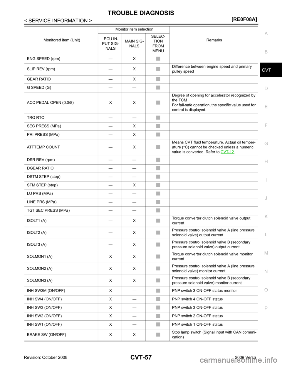
ENG SPEED (rpm) — X
SLIP REV (rpm) — X Difference between engine speed and primary
pulley speed
GEAR RATIO — X
G SPEED (G) — —
ACC PEDAL OPEN (0.0/8) X X Degree of opening for accelerator recognized by
the TCM
For fail-safe operation, the specific value used for
control is displayed.
TRQ RTO — —
SEC PRESS (MPa) — X
PRI PRESS (MPa) — X
ATFTEMP COUNT — X Means CVT fluid temperature. Actual oil temper-
ature ( °C) cannot be checked unless a numeric
value is converted. Refer to CVT-12 .
DSR REV (rpm) — —
DGEAR RATIO — —
DSTM STEP (step) — —
STM STEP (step) — X
LU PRS (MPa) — —
LINE PRS (MPa) — —
TGT SEC PRESS (MPa) — —
ISOLT1 (A) — X Torque converter clutch solenoid valve output
current
ISOLT2 (A) — X Pressure control solenoid valve A (line pressure
solenoid valve) output current
ISOLT3 (A) — X Pressure control solenoid valve B (secondary
pressure solenoid valve) output current
SOLMON1 (A) X X Torque converter clutch solenoid valve monitor
current
SOLMON2 (A) X X Pressure control solenoid valve A (line pressure
solenoid valve) monitor current
SOLMON3 (A) X X Pressure control solenoid valve B (secondary
pressure solenoid va lve) monitor current
INH SW3M (ON/OFF) X — PNP switch 3 ON-OFF status monitor
INH SW4 (ON/OFF) X — PNP switch 4 ON-OFF status
INH SW3 (ON/OFF) X — PNP switch 3 ON-OFF status
INH SW2 (ON/OFF) X — PNP switch 2 ON-OFF status
INH SW1 (ON/OFF) X — PNP switch 1 ON-OFF status
BRAKE SW (ON/OFF) X X Stop lamp switch (Signal input with CAN comuni-
cation)
Monitored item (Unit)
Monitor item selection
Remarks
ECU IN-
PUT SIG- NALS MAIN SIG-
NALS SELEC-
TION
FROM
MENU