Page 221 of 4331

.
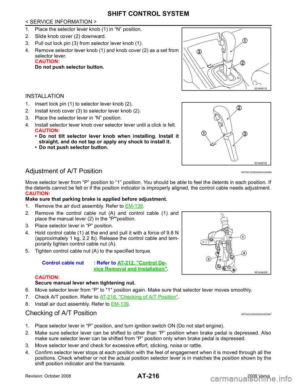
2. Remove the control cable nut (A) and control cable (1) and place the manual lever (2) in the "P'"position.
3. Place selector lever in “P” position.
4. Hold control cable (1) at the end and pull it with a force of 9.8 N (approximately 1 kg, 2.2 lb). Release the control cable and tem-
porarily tighten control cable nut (A).
5. Tighten control cable nut (A) to the specified torque.
CAUTION:
Secure manual lever when tightening nut.
6. Move selector lever from “P” to "1" position again. Make sure that selector lever moves smoothly.
7. Check A/T position. Refer to AT-216, " Checking of A/T Position " .
8. Install air duct assembly. Refer to EM-139 .
Checking of A/T Position INFOID:0000000004305497
1. Place selector lever in “P” position, and tu rn ignition switch ON (Do not start engine).
2. Make sure selector lever can be shifted to other than “P” position when brake pedal is depressed. Also
make sure selector lever can be shifted from “P” position only when brake pedal is depressed.
3. Move selector lever and check for excessive effort, sticking, noise or rattle.
4. Confirm selector lever stops at each position with the feel of engagement when it is moved through all the
positions. Check whether or not the actual position sele ctor lever is in matches the position shown by the
shift position indicator and the transaxle. SCIA6972E
Control De-
vice Removal and Installation " .
Page 231 of 4331
![NISSAN LATIO 2009 Service Repair Manual " Control Device Removal and Installation " .
4. Loosen PNP switch bolts. :Bolt
5. Insert the pin (3) [4 mm (0.16 in) dia.] straight into manual shaft (1) adjustment hole.
6. Rotate PNP switch (2) NISSAN LATIO 2009 Service Repair Manual " Control Device Removal and Installation " .
4. Loosen PNP switch bolts. :Bolt
5. Insert the pin (3) [4 mm (0.16 in) dia.] straight into manual shaft (1) adjustment hole.
6. Rotate PNP switch (2)](/manual-img/5/57359/w960_57359-230.png)
" Control Device Removal and Installation " .
4. Loosen PNP switch bolts. :Bolt
5. Insert the pin (3) [4 mm (0.16 in) dia.] straight into manual shaft (1) adjustment hole.
6. Rotate PNP switch (2) until the pin (3) can also be inserted straight into hole in PNP switch (2).
7. Tighten PNP switch bolts to the specified torque. Refer to "COMPONENTS".
8. Remove the pin (3) from adjustment hole after adjusting PNP switch (2).
9. Install the control cable. Refer to AT-212, " Control Device Removal and Installation " .
10. Adjust and check A/T position. Refer to AT-216, " Adjustment of A/T Position " and
AT-216, " Checking of A/
T Position " .
11. Check continuity of PNP switch (2). Refer to AT-176, " Component Inspection " .
12. Install the air duct (inlet). Refer to EM-139 .
Revolution Sensor INFOID:0000000004305505
COMPONENTS
REMOVAL AND INSTALLATION
Removal
1. Disconnect the battery negative terminal.
2. Remove air duct (inlet), air duct and air cleaner case. Refer to EM-139, " Component " .
Page 238 of 4331

AT
N
O P
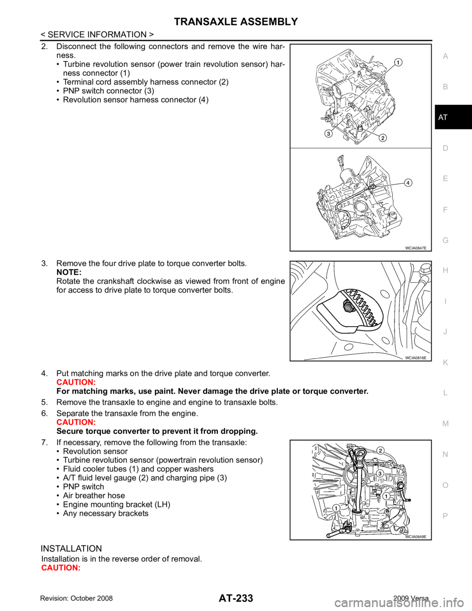
2. Disconnect the following connectors and remove the wire har-
ness.
• Turbine revolution sensor (power train revolution sensor) har-
ness connector (1)
• Terminal cord assembly harness connector (2)
• PNP switch connector (3)
• Revolution sensor harness connector (4)
3. Remove the four drive plate to torque converter bolts. NOTE:
Rotate the crankshaft clockwise as viewed from front of engine
for access to drive plate to torque converter bolts.
4. Put matching marks on the drive plate and torque converter. CAUTION:
For matching marks, use paint. Never dama ge the drive plate or torque converter.
5. Remove the transaxle to engine and engine to transaxle bolts.
6. Separate the transaxle from the engine. CAUTION:
Secure torque converter to prevent it from dropping.
7. If necessary, remove the following from the transaxle: • Revolution sensor
• Turbine revolution sensor (powertrain revolution sensor)
• Fluid cooler tubes (1) and copper washers
• A/T fluid level gauge (2) and charging pipe (3)
• PNP switch
• Air breather hose
• Engine mounting bracket (LH)
• Any necessary brackets
INSTALLATION Installation is in the reverse order of removal.
CAUTION: WCIA0616E
WCIA0648E
Page 239 of 4331
.
• After converter is installed to drive plate, ro tate crankshaft several turns to check that transaxle
rotates freely without binding.
• When installing the torque converter to the transaxle measure dis- tance A.
• Check the fitting of the dowel pins when installing the transaxle
assembly and the engine assembly.
: Dowel pin
• When installing the transaxle to the engine, align t he matching mark on the drive plate with the matching
mark on the torque converter.
• When securing the transaxle to the engine, attach the bolts in accordance with the following standard.
HR16DE engine models
(A): A/T to engine
(B): Engine to A/T
• When installing the transaxle to the engine, align t he matching mark on the drive plate with the matching
mark on the torque converter.
• When securing the transaxle to the engine, attach the bolts in accordance with the following standard.
Dimension A: 14.4 mm (0.567 in) or more
SCIA7698E
Page 240 of 4331
AT
N
O P
MR18DE engine models
(A): A/T to engine
(B): Engine to A/T
• Align the positions for the bolts on drive plate with those of the torque converter, and temporarily tighten bolts. Then, tighten bolts
to the specified torque.
• After completing installation, chec k for A/T fluid leakage, A/T fluid
level and A/T positions. Refer to AT-17, " Checking A/T Fluid " and
AT-216, " Checking of A/T Position " .
Bolt No. 1 2
Number of bolts 2 7
Bolt length “L”
[mm (in)] 55 (2.17) 50 (1.97)
Tightening torque
[N·m (kg-m, ft-lb)] 62 (6.3, 46)
Page 242 of 4331
AT
N
O P
1. Pinion mate gear thrust washer 2. Pinion mate gear 3. Pinion mate shaft
4. Lock pin 5. Side gear 6. Side gear thrust washer
7. Differential side bearing 8. Speedometer drive gear 9. Differential case
10. Final gear 11. Differential side bearing adjusting shim 12. Plug
13. O-ring 14. Bracket 15. RH differential side oil seal
16. Torque converter 17. Converter housing 18. Differential lubricant tube
19. Clip 20. O-ring 21. O-ring
22. Oil pump housing oil seal 23. Oil pump housing 24. Outer gear
25. Inner gear 26. Oil pump cover 27. Seal ring
28. Oil pump assembly
Page 250 of 4331
AT
N
O P
7. Differential side bearing 8. Speedometer drive gear 9. Differential case
10. Final gear 11. Differential side bearing adjusting shim12. Speedometer pinion
13. O-ring 14. Bracket 15. RH differential side oil seal
16. Torque converter 17. Converter housing 18. Differential lubricant tube
19. Clip 20. O-ring 21. O-ring
22. Oil pump housing oil seal 23. Oil pump housing 24. Outer gear
25. Inner gear 26. Oil pump cover 27. Seal ring
28. Oil pump assembly
Page 282 of 4331
AT
N
O P
9. Install detent spring on transaxle case.
10. Tighten detent spring bolt to the specified torque. Refer to AT-274, " Manual Shaft " .
Oil Pump INFOID:0000000004305516
COMPONENTS
DISASSEMBLY 1. Remove seal rings (1) from oil pump assembly (2).