Page 381 of 4331
![NISSAN LATIO 2009 Service Repair Manual Number of drive plates
5
Number of driven plates 5
Drive plate thickness [mm (in)] Standard 1.8 (0.071)
Allowable limit 1.6 (0.063)
Driven plate thickness [mm (in)] Standard 2.0 (0.079)
Clearance [mm NISSAN LATIO 2009 Service Repair Manual Number of drive plates
5
Number of driven plates 5
Drive plate thickness [mm (in)] Standard 1.8 (0.071)
Allowable limit 1.6 (0.063)
Driven plate thickness [mm (in)] Standard 2.0 (0.079)
Clearance [mm](/manual-img/5/57359/w960_57359-380.png)
Number of drive plates
5
Number of driven plates 5
Drive plate thickness [mm (in)] Standard 1.8 (0.071)
Allowable limit 1.6 (0.063)
Driven plate thickness [mm (in)] Standard 2.0 (0.079)
Clearance [mm (in)] Standard 0.45 - 0.85 (0.0177 - 0.0335)
Allowable limit 1.85 (0.0728) Number of drive plates
3
Number of driven plates 4
Drive plate thickness [mm (in)] Standard 1.6 (0.063)
Allowable limit 1.4 (0.055)
Driven plate thickness [mm (in)] Standard 2.0 (0.079)
Clearance [mm (in)] Standard 1.0 - 1.4 (0.039 - 0.055)
Allowable limit 2.0 (0.079) Applied model HR16DE engine MR18DE engine
Number of drive plates 4 5
Number of driven plates 4 5
Drive plate thickness [mm
(in)] Standard 2.0 (0.079) 2.0 (0.079)
Allowable limit 1.8 (0.071) 1.8 (0.071)
Driven plate thickness [mm
(in)] Standard 2.0 (0.079) 2.0 (0.079)
Clearance [mm (in)] Standard 1.4 - 1.8 (0.055 - 0.071) 1.4 - 1.8 (0.055 - 0.071)
Allowable limit 2.6 (0.102) 2.8 (0.110) Anchor end pin tightening torque [N·m (kg-m, in-lb)] 4.9 (0.50, 43)
Number of returning revolutions for anchor end pin 2.5
Lock nut tightening torque [N·m (kg-m, ft-lb)] 33.9 (3.5, 25)
Page 382 of 4331

AT
N
O P
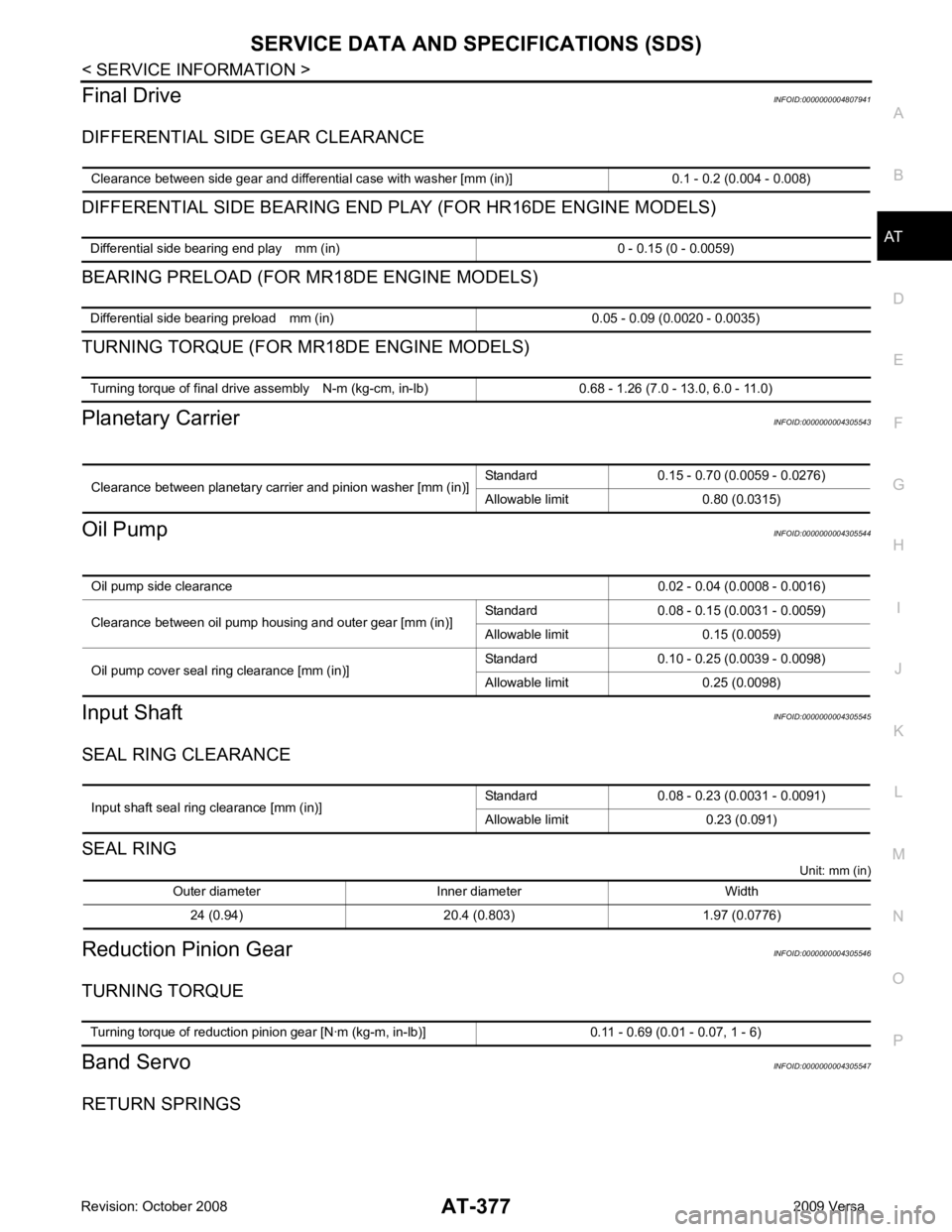
Final Drive
INFOID:0000000004807941
DIFFERENTIAL SIDE GEAR CLEARANCE
DIFFERENTIAL SIDE BEARING END PL AY (FOR HR16DE ENGINE MODELS)
BEARING PRELOAD (FOR MR18DE ENGINE MODELS)
TURNING TORQUE (FOR MR18DE ENGINE MODELS)
Planetary Carrier INFOID:0000000004305543
Oil Pump INFOID:0000000004305544
Input Shaft INFOID:0000000004305545
SEAL RING CLEARANCE
SEAL RING Unit: mm (in)
Reduction Pinion Gear INFOID:0000000004305546
TURNING TORQUE
Band Servo INFOID:0000000004305547
RETURN SPRINGS Clearance between side gear and differential case with washer [mm (in)] 0.1 - 0.2 (0.004 - 0.008) Differential side bearing end play mm (in) 0 - 0.15 (0 - 0.0059)
Differential side bearing preload mm (in) 0.05 - 0.09 (0.0020 - 0.0035)
Turning torque of final drive assembly N-m (kg-cm, in-lb) 0.68 - 1.26 (7.0 - 13.0, 6.0 - 11.0)
Clearance between planetary carrier and pinion washer [mm (in)]
Standard 0.15 - 0.70 (0.0059 - 0.0276)
Allowable limit 0.80 (0.0315) Oil pump side clearance
0.02 - 0.04 (0.0008 - 0.0016)
Clearance between oil pump housing and outer gear [mm (in)] Standard 0.08 - 0.15 (0.0031 - 0.0059)
Allowable limit 0.15 (0.0059)
Oil pump cover seal ring clearance [mm (in)] Standard 0.10 - 0.25 (0.0039 - 0.0098)
Allowable limit 0.25 (0.0098) Input shaft seal ring clearance [mm (in)]
Standard 0.08 - 0.23 (0.0031 - 0.0091)
Allowable limit 0.23 (0.091) Outer diameter Inner diameter Width
24 (0.94) 20.4 (0.803) 1.97 (0.0776) Turning torque of reduction pinion gear [N·m (kg-m, in-lb)] 0.11 - 0.69 (0.01 - 0.07, 1 - 6)
Page 383 of 4331
Output shaft seal ring clearance [mm (in)]
Standard 0.10 - 0.25 (0.0039 - 0.0098)
Allowable limit 0.25 (0.0098) Outer diameter Inner diameter Width
29.5 (1.161) 26.2 (1.031) 1.95 (0.0768) Turning torque of output shaft ·m (kg-m, in-lb) 0.25 - 0.88 (0.03 - 0.08, 3 - 7)
Output shaft end play mm (in) 0 - 0.5 (0 - 0.020)
Bearing retainer seal ring clearance [mm (in)]
Standard 0.10 - 0.27 (0.0039 - 0.0106)
Allowable limit 0.27 (0.0106) Total end play [mm (in)] 0.25 - 0.55 (0.0098 - 0.0217)
Reverse clutch end play [mm (in)] 0.65 - 1.0 (0.0256 - 0.039)
Engine
HR16DE MR18DE
Distance between end of converter housing and torque converter [mm (in)] 16.2 (0.638) 14.4 (0.567) Gear position 1 2 3 4
Shift solenoid valve A ON (Closed) OFF (Open) OFF (Open) ON (Closed)
Shift solenoid valve B ON (Closed) ON (Closed) OFF (Open) OFF (Open)
Page 384 of 4331
AT
N
O P
Solenoid Valves
INFOID:0000000004305554
A/T Fluid Temperature Sensor INFOID:0000000004305555
Remarks: Specification data are reference values.
Revolution Sensor INFOID:0000000004305556
Dropping Resistor INFOID:0000000004305557
Turbine Revolution Sensor (Power Train Revolution Sensor) INFOID:0000000004305558
Solenoid valve designation Resistance (Approx.) Terminal
Shift solenoid valve A 20 - 30 Ω2
Shift solenoid valve B 5 - 20 Ω1
Overrun clutch solenoid valve 20 - 30 Ω3
Line pressure solenoid valve 2.5 - 5.0 Ω4
Torque converter clutch solenoid valve 5 - 20 Ω5Condition Specification (Approx.)
Cold [20 °C (68 °F)]
↓
Hot [80 °C (176 °F)] 1.5V
↓
0.5V 2.5 k
Ω
↓
0.3 k Ω Resistance
12Ω (Approx.) Condition Judgment standard
When driving at 20 km/h (12 MPH) 360 Hz (Approx.)
Page 474 of 4331

BL
N
O P
HOOD
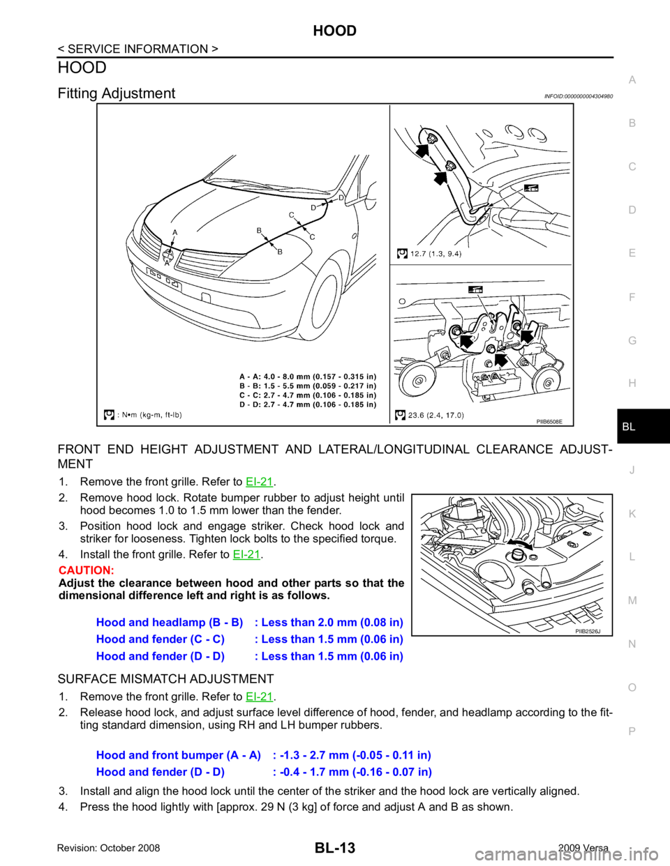
Fitting Adjustment INFOID:0000000004304980
FRONT END HEIGHT ADJUSTMENT AND LA TERAL/LONGITUDINAL CLEARANCE ADJUST-
MENT
1. Remove the front grille. Refer to EI-21 .
2. Remove hood lock. Rotate bumper rubber to adjust height until hood becomes 1.0 to 1.5 mm lower than the fender.
3. Position hood lock and engage striker. Check hood lock and striker for looseness. Tighten lock bolts to the specified torque.
4. Install the front grille. Refer to EI-21 .
CAUTION:
Adjust the clearance between hood and other parts so that the
dimensional difference left and right is as follows.
SURFACE MISMATCH ADJUSTMENT 1. Remove the front grille. Refer to EI-21 .
2. Release hood lock, and adjust surface level difference of hood, fender, and headlamp according to the fit- ting standard dimension, using RH and LH bumper rubbers.
3. Install and align the hood lock until the center of the striker and the hood lock are vertically aligned.
4. Press the hood lightly with [approx. 29 N (3 kg] of force and adjust A and B as shown.
Page 770 of 4331

BL
N
O P
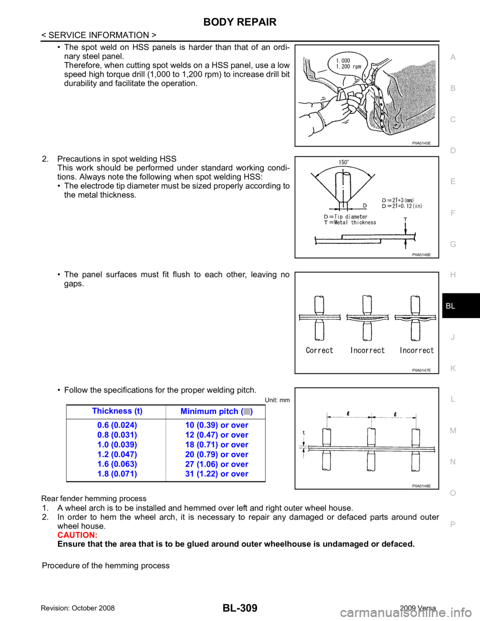
• The spot weld on HSS panels is harder than that of an ordi-
nary steel panel.
Therefore, when cutting spot welds on a HSS panel, use a low
speed high torque drill (1,000 to 1,200 rpm) to increase drill bit
durability and facilitate the operation.
2. Precautions in spot welding HSS This work should be performed under standard working condi-
tions. Always note the following when spot welding HSS:
• The electrode tip diameter must be sized properly according to the metal thickness.
• The panel surfaces must fit flush to each other, leaving no gaps.
• Follow the specifications for the proper welding pitch. Unit: mm
Rear fender hemming process 1. A wheel arch is to be installed and hemmed over left and right outer wheel house.
2. In order to hem the wheel arch, it is necessary to repair any damaged or defaced parts around outer
wheel house.
CAUTION:
Ensure that the area that is to be glued around outer wheelhouse is undamaged or defaced.
Procedure of the hemming process PIIA0146E
PIIA0147E
Page 803 of 4331

BR
N
O P
5. When the repair work is completed, return the ignition switch to the
″LOCK ″ position before connecting
the battery cables. (At this time, the steering lock mechanism will engage.)
6. Perform a self-diagnosis check of al l control units using CONSULT-III.
Precaution for Brake System INFOID:0000000004305887
• Refill using recommended brake fluid. Refer to MA-14 .
• Never reuse drained brake fluid.
• Be careful not to splash brake fluid on painted surfac e of body. If brake fluid is splashed on painted surfaces
of body immediately wipe it off with cloth and then wash it away with water.
• To clean or wash all parts of master cylinder, disc brake caliper and wheel cylinder, use new brake fluid.
• Never use mineral oils such as gasoline or kerosene. They will ruin rubber parts of the hydraulic system.
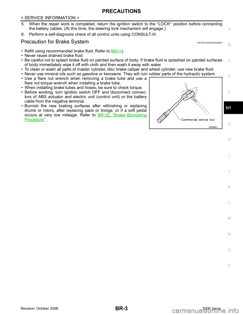
• Use a flare nut wrench when removing a brake tube and use a flare nut torque wrench when installing a brake tube.
• When installing brake tubes and hoses, be sure to check torque.
• Before working, turn igniti on switch OFF and disconnect connec-
tors of ABS actuator and electric unit (control unit) or the battery
cable from the negative terminal.
• Burnish the new braking surfaces after refinishing or replacing drums or rotors, after replacing p ads or linings, or if a soft pedal
occurs at very low mileage. Refer to BR-32, " Brake Burnishing
Procedure " .
Page 804 of 4331
ALFIA0092ZZ
Tool name Description
1. Flare nut crowfoot
2. Torque wrench Removing and installing brake piping
a: 10 mm (0.39 in) / 12 mm (0.47 in)
Pin punch Removing and installing reservoir tank pin
Tip diameter: 4 mm (0.16 in)
Power tool Removing nuts, bolts and screwsZZA0515D
PIIB1407E