Page 812 of 4331
Fluids and Lubricants " .
• Never reuse drained brake fluid.
Front Brake Tube and Hose INFOID:0000000004305896
REMOVAL
1. Drain brake fluid. Refer to BR-9, " Drain and Refill " .
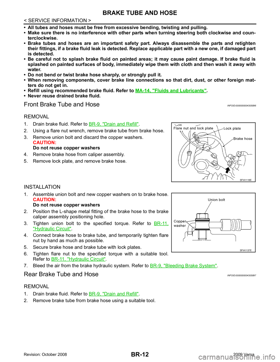
2. Using a flare nut wrench, remove brake tube from brake hose.
3. Remove union bolt and discard the copper washers. CAUTION:
Do not reuse copper washers
4. Remove brake hose from caliper assembly.
5. Remove lock plate, and remove brake hose.
INSTALLATION
1. Assemble union bolt and new copper washers on to brake hose. CAUTION:
Do not reuse copper washers
2. Position the L-shape metal fitting of the brake hose to the brake caliper assembly positioning hole.
3. Tighten union bolt to the specified torque. Refer to BR-11," Hydraulic Circuit " .
4. Connect brake hose to brake tube, and temporarily tighten flare nut by hand as much as possible.
5. Secure brake hose and brake tube with lock plates.
6. Tighten flare nut to the specified torque with a suitable tool. Refer to BR-11, " Hydraulic Circuit " .
7. Bleed the air from the brake hydraulic system. Refer to BR-9, " Bleeding Brake System " .
Rear Brake Tube and Hose INFOID:0000000004305897
REMOVAL
1. Drain brake fluid. Refer to BR-9, " Drain and Refill " .
2. Remove brake tube from brake hose using a suitable tool.
Page 813 of 4331
BR
N
O P
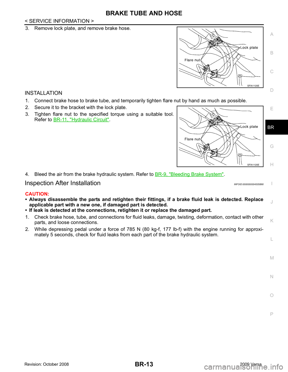
3. Remove lock plate, and remove brake hose.
INSTALLATION 1. Connect brake hose to brake tube, and temporaril y tighten flare nut by hand as much as possible.
2. Secure it to the bracket with the lock plate.
3. Tighten flare nut to the specified torque using a suitable tool. Refer to BR-11, " Hydraulic Circuit " .
4. Bleed the air from the brake hydraulic system. Refer to BR-9, " Bleeding Brake System " .
Inspection After Installation INFOID:0000000004305898
CAUTION:
• Always disassemble the parts and retighten their fitti ngs, if a brake fluid leak is detected. Replace
applicable part with a new one, if damaged part is detected.
• If leak is detected at the connections, retighten it or replace the damaged part.
1. Check brake hose, tube, and connections for fluid leak s, damage, twisting, deformation, contact with other
parts, and loose connections.
2. While depressing pedal under a force of 785 N (80 kg-f, 177 lb-f) with the engine running for approxi- mately 5 seconds, check for fluid leaks from each part of the brake hydraulic system. SFIA1120E
Page 816 of 4331
Fluids and Lubricants " .
• Never reuse drained brake fluid.
• Check if the rod of primary piston has dust or scratches.
1. Install master cylinder to brake booster assembly, and tighten nuts to the specified torque.
CAUTION:
• Do not damage or strain rod of primary piston.
• Apply silicone grease for O-ring, primary piston rod and to inside of booster.
2. Install brake tube to master cylinder, and temporarily tighten the flare nuts on the brake tube to master cyl-
inder by hand.
3. Install brake tube to brake hose, then tighten flare nut to the specified torque using a flare nut torque
wrench. Refer to BR-11, " Hydraulic Circuit " .
4. Connect the clutch hose to the reservoir tank, if equipped.
5. Connect brake fluid level switch harness connector.
6. Refill with new brake fluid and bleed the air from the brake hydraulic system. Refer toBR-9, " Bleeding
Brake System " .
Disassembly and Assembly INFOID:0000000004305903
COMPONENTS
DISASSEMBLY
Page 822 of 4331
Inspection and Adjustment " .
7. Tighten lock nut of input rod to the specified torque.
8. Install vacuum hose into brake booster. Refer to BR-23, " Removal and Installation " .
9. Bleed the air from the brake hydraulic system. Refer to BR-9, " Bleeding Brake System " .
Input rod length (B) : Refer to
BR-40, " Brake Booster " .
Page 827 of 4331
BR
N
O P
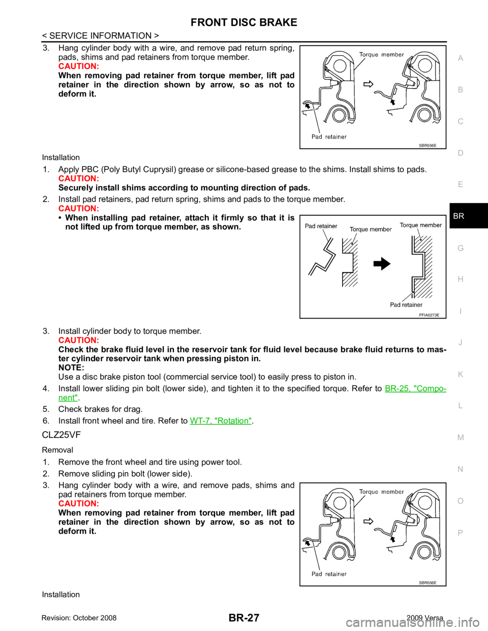
3. Hang cylinder body with a wire, and remove pad return spring,
pads, shims and pad retainers from torque member.
CAUTION:
When removing pad retainer from torque member, lift pad
retainer in the direction shown by arrow, so as not to
deform it.
Installation 1. Apply PBC (Poly Butyl Cuprysil) grease or silicone- based grease to the shims. Install shims to pads.
CAUTION:
Securely install shims according to mounting direction of pads.
2. Install pad retainers, pad return spring, shims and pads to the torque member. CAUTION:
• When installing pad retainer, at tach it firmly so that it is
not lifted up from torque member, as shown.
3. Install cylinder body to torque member. CAUTION:
Check the brake fluid level in the reservoir tank for fluid level because brake fluid returns to mas-
ter cylinder reservoir tank when pressing piston in.
NOTE:
Use a disc brake piston tool (commercial se rvice tool) to easily press to piston in.
4. Install lower sliding pin bolt (lower side), and tighten it to the specified torque. Refer to BR-25, " Compo-
nent " .
5. Check brakes for drag.
6. Install front wheel and tire. Refer to WT-7, " Rotation " .
CLZ25VF
Removal 1. Remove the front wheel and tire using power tool.
2. Remove sliding pin bolt (lower side).
3. Hang cylinder body with a wire, and remove pads, shims and pad retainers from torque member.
CAUTION:
When removing pad retainer from torque member, lift pad
retainer in the direction shown by arrow, so as not to
deform it.
Installation SBR556E
Page 829 of 4331
BR
N
O P
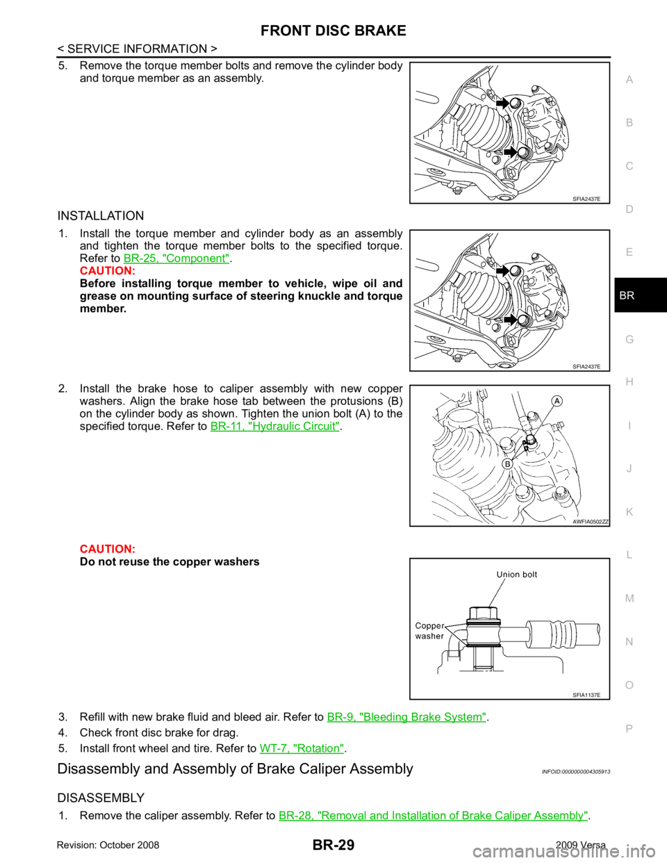
5. Remove the torque member bolts and remove the cylinder body
and torque member as an assembly.
INSTALLATION 1. Install the torque member and cylinder body as an assembly and tighten the torque member bolts to the specified torque.
Refer to BR-25, " Component " .
CAUTION:
Before installing torque member to vehicle, wipe oil and
grease on mounting surface of steering knuckle and torque
member.
2. Install the brake hose to caliper assembly with new copper washers. Align the brake hose tab between the protusions (B)
on the cylinder body as shown. Tighten the union bolt (A) to the
specified torque. Refer to BR-11, " Hydraulic Circuit " .
CAUTION:
Do not reuse the copper washers
3. Refill with new brake fluid and bleed air. Refer to BR-9, " Bleeding Brake System " .
4. Check front disc brake for drag.
5. Install front wheel and tire. Refer to WT-7, " Rotation " .
Disassembly and Assembly of Brake Caliper Assembly INFOID:0000000004305913
DISASSEMBLY 1. Remove the caliper assembly. Refer to BR-28, " Removal and Installation of Brake Caliper Assembly " .AWFIA0502ZZ
SFIA1137E
Page 830 of 4331
BR-30< SERVICE INFORMATION >
FRONT DISC BRAKE
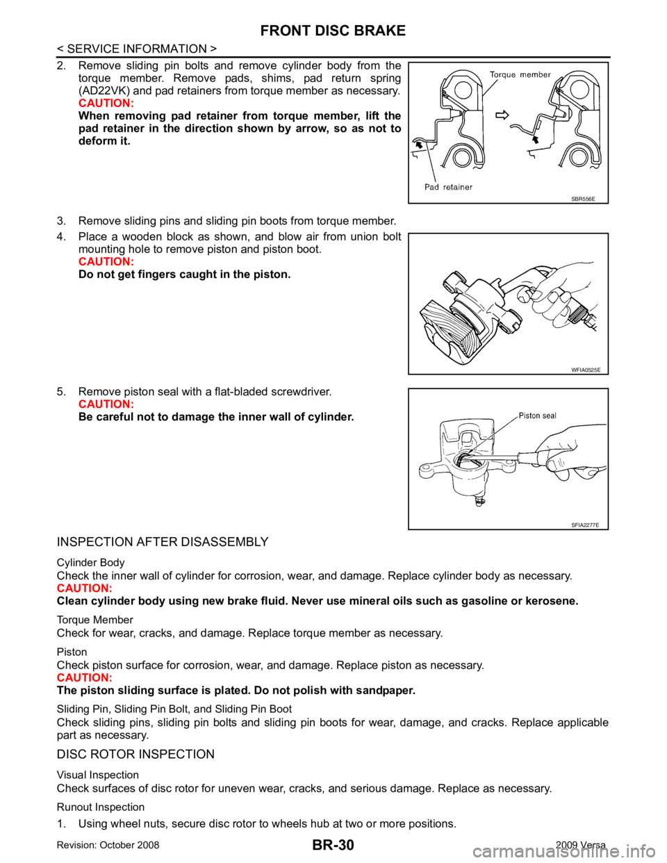
2. Remove sliding pin bolts and remove cylinder body from the torque member. Remove pads, shims, pad return spring
(AD22VK) and pad retainers from torque member as necessary.
CAUTION:
When removing pad retainer fr om torque member, lift the
pad retainer in the direction shown by arrow, so as not to
deform it.
3. Remove sliding pins and sliding pin boots from torque member.
4. Place a wooden block as shown, and blow air from union bolt mounting hole to remove piston and piston boot.
CAUTION:
Do not get fingers caught in the piston.
5. Remove piston seal with a flat-bladed screwdriver. CAUTION:
Be careful not to damage the inner wall of cylinder.
INSPECTION AFTER DISASSEMBLY
Cylinder Body
Check the inner wall of cylinder for corrosion, w ear, and damage. Replace cylinder body as necessary.
CAUTION:
Clean cylinder body using new brake fluid. Never use mineral oils such as gasoline or kerosene.
Torque Member
Check for wear, cracks, and damage. R eplace torque member as necessary.
Piston
Check piston surface for corrosion, wear, and damage. Replace piston as necessary.
CAUTION:
The piston sliding surface is plated . Do not polish with sandpaper.
Sliding Pin, Sliding Pin Bolt, and Sliding Pin Boot
Check sliding pins, sliding pin bolts and sliding pin boots for wear, damage, and cracks. Replace applicable
part as necessary.
DISC ROTOR INSPECTION
Visual Inspection
Check surfaces of disc rotor for uneven wear, cr acks, and serious damage. Replace as necessary.
Runout Inspection
1. Using wheel nuts, secure disc rotor to wheels hub at two or more positions. SBR556E
WFIA0525E
SFIA2277E
Page 832 of 4331
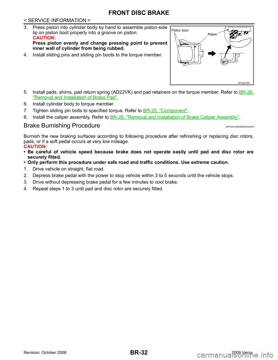
" Removal and Installation of Brake Pad " .
6. Install cylinder body to torque member.
7. Tighten sliding pin bolts to specified torque. Refer to BR-25, " Component " .
8. Install the caliper assembly. Refer to BR-28, " Removal and Installation of Brake Caliper Assembly " .
Brake Burnishing Procedure INFOID:0000000004305914
Burnish the new braking surfaces according to following procedure after refinishing or replacing disc rotors,
pads, or if a soft pedal occurs at very low mileage.
CAUTION:
• Be careful of vehicle speed because brake does not operate easily until pad and disc rotor are
securely fitted.
• Only perform this procedure under safe road and traffic conditions. Use extreme caution.
1. Drive vehicle on straight, flat road.
2. Depress brake pedal with the power to stop vehicl e within 3 to 5 seconds until the vehicle stops.
3. Drive without depressing brake pedal for a few minutes to cool brake.
4. Repeat steps 1 to 3 until pad and disc rotor are securely fitted.