Page 3212 of 4331
FRONT DRIVE SHAFT
FAX-17
< SERVICE INFORMATION >
C
E F
G H
I
J
K L
M A
B FAX
N
O P
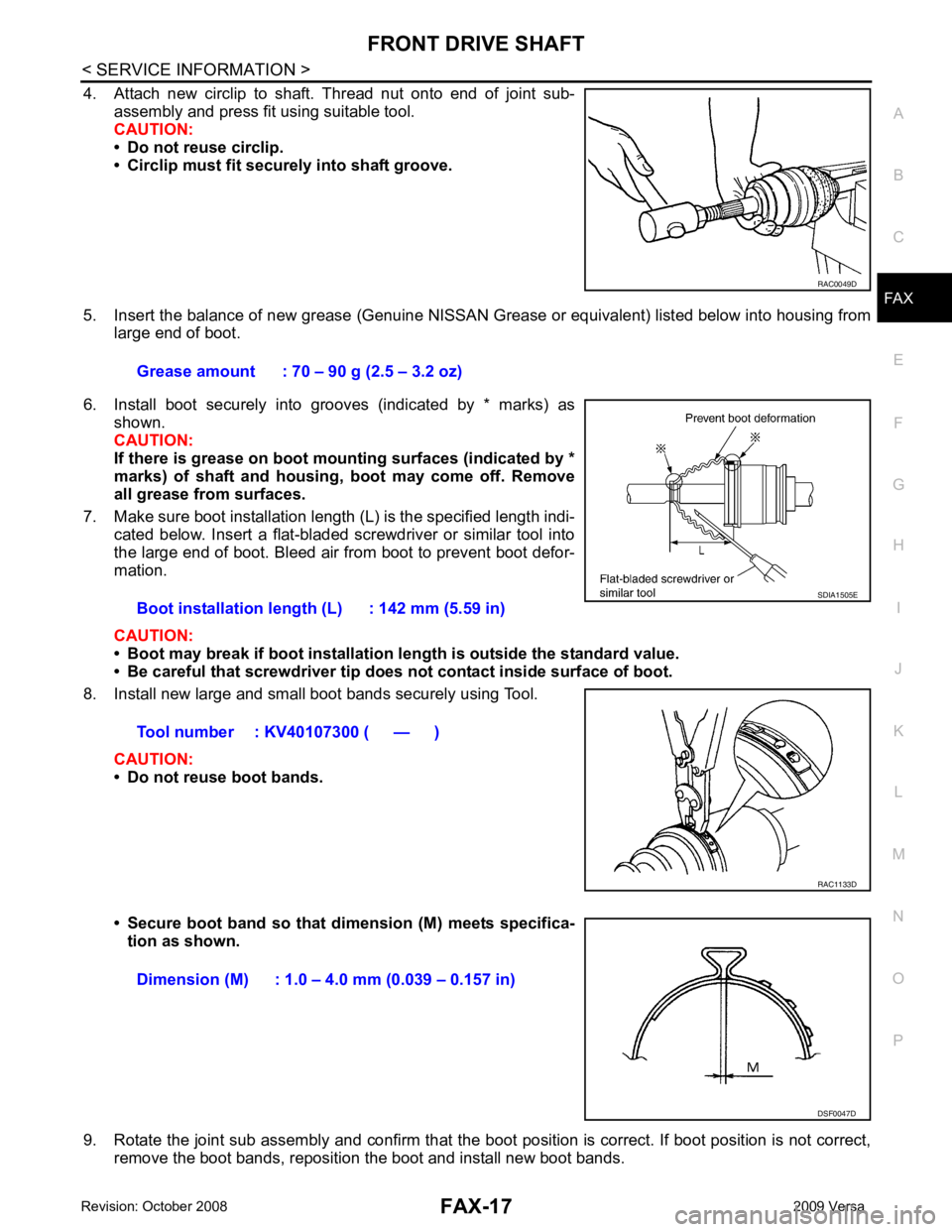
4. Attach new circlip to shaft. Thread nut onto end of joint sub-
assembly and press fit using suitable tool.
CAUTION:
• Do not reuse circlip.
• Circlip must fit securely into shaft groove.
5. Insert the balance of new grease (Genuine NISSAN Grease or equivalent) listed below into housing from
large end of boot.
6. Install boot securely into grooves (indicated by * marks) as shown.
CAUTION:
If there is grease on boot mounting surfaces (indicated by *
marks) of shaft and housing, boot may come off. Remove
all grease from surfaces.
7. Make sure boot installation length (L) is the specified length indi- cated below. Insert a flat-bladed screwdriver or similar tool into
the large end of boot. Bleed air from boot to prevent boot defor-
mation.
CAUTION:
• Boot may break if boot installation le ngth is outside the standard value.
• Be careful that screwdriver tip does not contact inside surface of boot.
8. Install new large and small boot bands securely using Tool.
CAUTION:
• Do not reuse boot bands.
• Secure boot band so that dimension (M) meets specifica- tion as shown.
9. Rotate the joint sub assembly and confirm that the boot position is correct. If boot position is not correct,
remove the boot bands, reposition the boot and install new boot bands. RAC0049D
Grease amount : 70 – 90 g (2.5 – 3.2 oz)
Boot installation length (L) : 142 mm (5.59 in)
Tool number : KV40107300 ( — ) SDIA1505E
RAC1133D
Dimension (M) : 1.0 – 4.0 mm (0.039 – 0.157 in)
DSF0047D
Page 3216 of 4331
FRONT DRIVE SHAFT
FAX-21
< SERVICE INFORMATION >
C
E F
G H
I
J
K L
M A
B FAX
N
O P
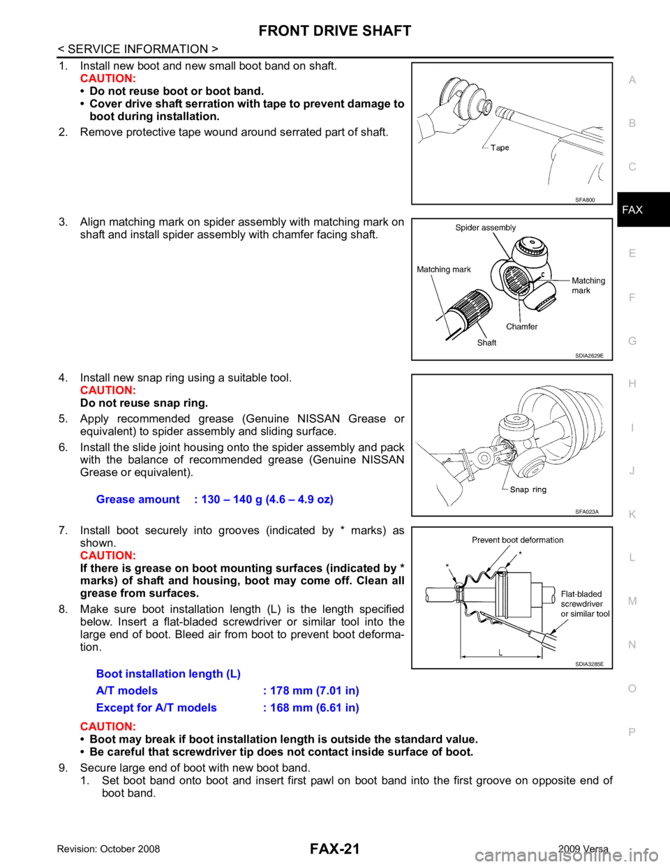
1. Install new boot and new small boot band on shaft.
CAUTION:
• Do not reuse boot or boot band.
• Cover drive shaft serration with tape to prevent damage to
boot during installation.
2. Remove protective tape wound around serrated part of shaft.
3. Align matching mark on spider assembly with matching mark on shaft and install spider assembly with chamfer facing shaft.
4. Install new snap ring using a suitable tool. CAUTION:
Do not reuse snap ring.
5. Apply recommended grease (Genuine NISSAN Grease or equivalent) to spider assembly and sliding surface.
6. Install the slide joint housing onto the spider assembly and pack with the balance of recommended grease (Genuine NISSAN
Grease or equivalent).
7. Install boot securely into grooves (indicated by * marks) as shown.
CAUTION:
If there is grease on boot mounting surfaces (indicated by *
marks) of shaft and housing, boot may come off. Clean all
grease from surfaces.
8. Make sure boot installation length (L) is the length specified below. Insert a flat-bladed screwdriver or similar tool into the
large end of boot. Bleed air from boot to prevent boot deforma-
tion.
CAUTION:
• Boot may break if boot installation le ngth is outside the standard value.
• Be careful that screwdriver tip does not contact inside surface of boot.
9. Secure large end of boot with new boot band. 1. Set boot band onto boot and insert first pawl on boot band into the first groove on opposite end of boot band. SFA800
SDIA2629E
Grease amount : 130 – 140 g (4.6 – 4.9 oz)
SFA023A
Boot installation length (L)
A/T models : 178 mm (7.01 in)
Except for A/T models : 168 mm (6.61 in) SDIA3285E
Page 3218 of 4331
FRONT DRIVE SHAFT
FAX-23
< SERVICE INFORMATION >
C
E F
G H
I
J
K L
M A
B FAX
N
O P
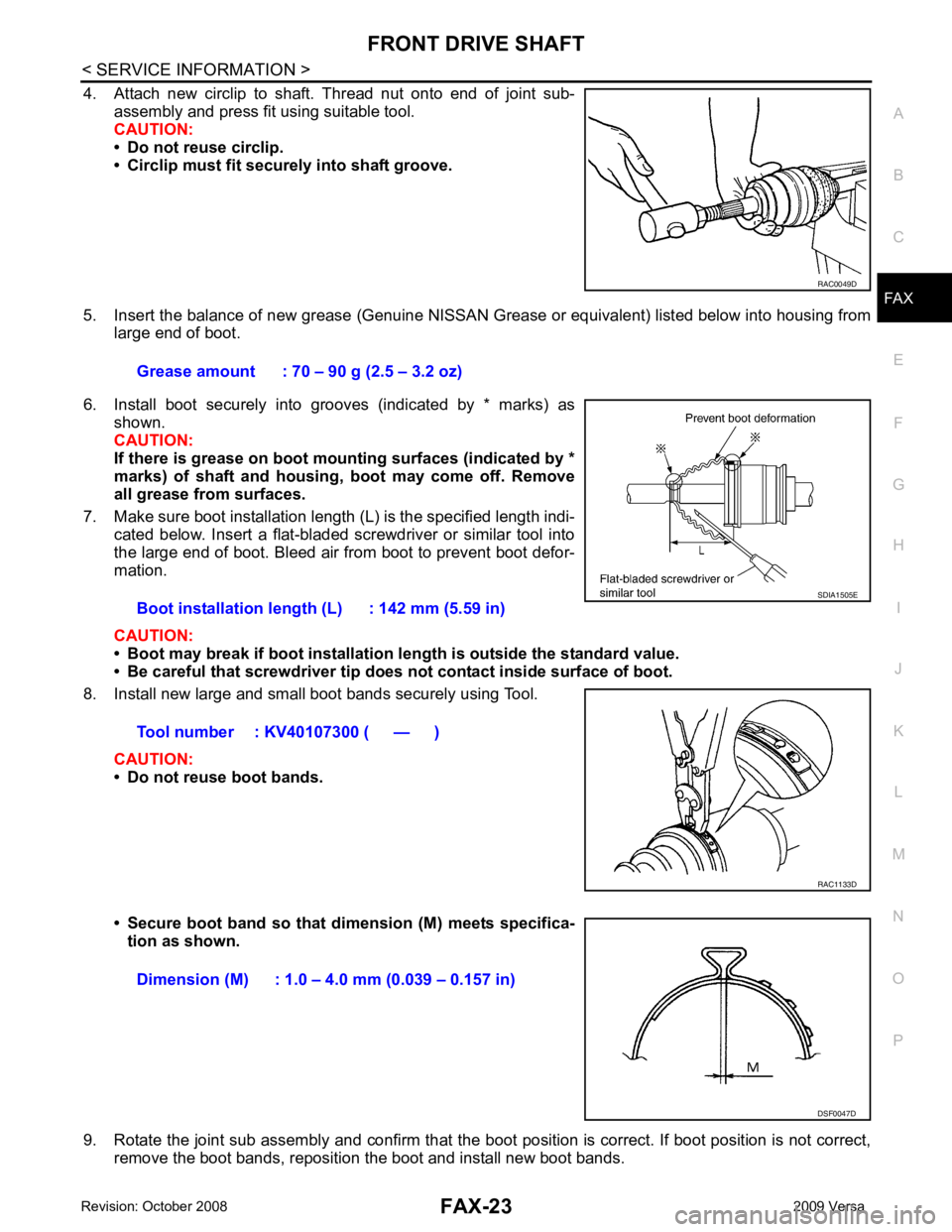
4. Attach new circlip to shaft. Thread nut onto end of joint sub-
assembly and press fit using suitable tool.
CAUTION:
• Do not reuse circlip.
• Circlip must fit securely into shaft groove.
5. Insert the balance of new grease (Genuine NISSAN Grease or equivalent) listed below into housing from
large end of boot.
6. Install boot securely into grooves (indicated by * marks) as shown.
CAUTION:
If there is grease on boot mounting surfaces (indicated by *
marks) of shaft and housing, boot may come off. Remove
all grease from surfaces.
7. Make sure boot installation length (L) is the specified length indi- cated below. Insert a flat-bladed screwdriver or similar tool into
the large end of boot. Bleed air from boot to prevent boot defor-
mation.
CAUTION:
• Boot may break if boot installation le ngth is outside the standard value.
• Be careful that screwdriver tip does not contact inside surface of boot.
8. Install new large and small boot bands securely using Tool.
CAUTION:
• Do not reuse boot bands.
• Secure boot band so that dimension (M) meets specifica- tion as shown.
9. Rotate the joint sub assembly and confirm that the boot position is correct. If boot position is not correct,
remove the boot bands, reposition the boot and install new boot bands. RAC0049D
Grease amount : 70 – 90 g (2.5 – 3.2 oz)
Boot installation length (L) : 142 mm (5.59 in)
Tool number : KV40107300 ( — ) SDIA1505E
RAC1133D
Dimension (M) : 1.0 – 4.0 mm (0.039 – 0.157 in)
DSF0047D
Page 3220 of 4331
SERVICE DATA AND SPECIFICATIONS (SDS)
FAX-25
< SERVICE INFORMATION >
C
E F
G H
I
J
K L
M A
B FAX
N
O P
SERVICE DATA AND SPECIFICATIONS (SDS)
Wheel Bearing INFOID:0000000004683860
Drive Shaft INFOID:0000000004305850
Dynamic Damper INFOID:0000000004305851
Boot Bands INFOID:0000000004683861
Unit: mm (in)
Axial end play limit
0.05 mm (0.002 in) or lessJoint type Wheel side Transaxle side
Grease quantity 70 - 90 g (2.5 - 3.2 oz) 130 - 140 g (4.6 - 4.9 oz)
Boots installed length Left side
142 mm (5.59 in) 181.2 mm (7.13 in) (M/T models)
176 mm (6.93 in) (Except for M/T models)
Right side 178 mm (7.01 in) (A/T models)
168 mm (6.61 in) (Exc ept for A/T models)Dimension A
Except for CVT models 230 – 236 mm (9.06 – 9.29 in)
CVT models 225 – 231 mm (8.86 – 9.09 in)
Dimension B 70 mm (2.76 in)FAC0156D
Dimension "M" 1.0 - 4.0 (0.039 - 0.157) DSF0047D
Page 3243 of 4331
FSU
N
O P
3. Put a mark on base line of the tread (rear side) of both tires at
the same height of hub center. These are measuring points.
4. Measure distance (A) from rear side.
5. Push vehicle slowly ahead to rotate wheels 180 degrees (1/2 turn).
CAUTION:
If wheels have rotated more than 180 degrees (1/2 turn), try
the above procedure again from the beginning. Never push
vehicle backward.
6. Measure distance (B) from front side.
7. Use the formula below to calculate total toe-in. • If the total toe-in is outside the specification, adj ust toe-in by varying the length of between steering
outer socket and inner socket. SFA234AC
Wheel Alignment (Unladen*) " .
Page 3258 of 4331
GI
N
O P
(i.e. Flexible Fuel Vehicle - FFV models). Using a fu
el other than that specified could adversely affect
the emission control devices and systems, and could also affect the warranty coverage validity.
Precaution for Multiport Fuel Inject ion System or Engine Control System INFOID:0000000004307350
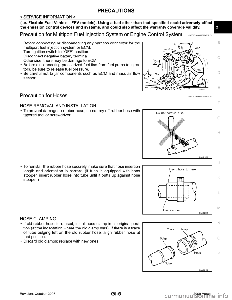
• Before connecting or disconnecti ng any harness connector for the
multiport fuel injection system or ECM:
Turn ignition switch to “OFF” position.
Disconnect negative battery terminal.
Otherwise, there may be damage to ECM.
• Before disconnecting pressurized fuel line from fuel pump to injec- tors, be sure to release fuel pressure.
• Be careful not to jar components such as ECM and mass air flow sensor.
Precaution for Hoses INFOID:0000000004307351
HOSE REMOVAL AND INSTALLATION • To prevent damage to rubber hose, do not pry off rubber hose with tapered tool or screwdriver.
• To reinstall the rubber hose securely, make sure that hose insertion length and orientation is correct. (If tube is equipped with hose
stopper, insert rubber hose into tube until it butts up against hose
stopper.)
HOSE CLAMPING • If old rubber hose is re-used, install hose clamp in its original posi- tion (at the indentation where the old clamp was). If there is a trace
of tube bulging left on the old rubber hose, align rubber hose at
that position.
• Discard old clamps; replace with new ones. SMA019D
SMA021D
Page 3811 of 4331
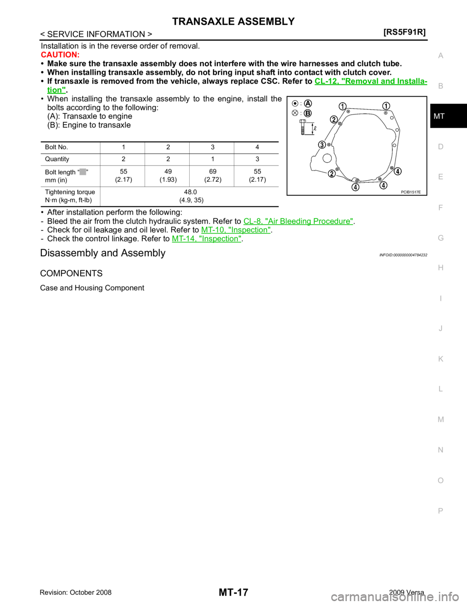
MT
N
O P
Installation is in the reverse order of removal.
CAUTION:
• Make sure the transaxle assembly does not interfer e with the wire harnesses and clutch tube.
• When installing transaxle assembly, do not bring input shaft into contact with clutch cover.
• If transaxle is removed from the vehicle, always replace CSC. Refer to CL-12, " Removal and Installa-
tion " .
• When installing the transaxle assembly to the engine, install the bolts according to the following:
(A): Transaxle to engine
(B): Engine to transaxle
• After installation perform the following:
- Bleed the air from the clutch hydraulic system. Refer to CL-8, " Air Bleeding Procedure " .
- Check for oil leakage and oil level. Refer to MT-10, " Inspection " .
- Check the control linkage. Refer to MT-14, " Inspection " .
Disassembly and Assembly INFOID:0000000004784232
COMPONENTS
Case and Housing Component Bolt No. 1 2 3 4
Quantity 2 2 1 3
Bolt length “ ”
mm (in) 55
(2.17) 49
(1.93) 69
(2.72) 55
(2.17)
Tightening torque
N·m (kg-m, ft-lb) 48.0
(4.9, 35)
Page 3853 of 4331
MT
N
O P
Installation is in the reverse order of removal.
CAUTION:
When installing transaxle assembly, be careful not to bring transaxle input shaft into contact with
clutch cover.
• If transaxle is removed from the v ehicle, always replace CSC. Refer to CL-12, " Removal and Installation " .
• When installing the transaxle assembly to the engine, install the
bolts as shown.
A: M/T to engine
B: Engine to M/T
• After installation, bleed the air from the clutch hydraulic system. Refer to CL-8, " Air Bleeding Procedure " .
• After installation, check oil level, and check for leaks and loose mechanisms. Refer to MT-52, " Checking M/T
Oil " .
Disassembly and Assembly INFOID:0000000004305279
COMPONENTS
Case and Housing Components Bolt No. 1 2
Quantity 3 6
Bolt length “ ” mm (in) 60 (2.36) 50 (1.97)
Tightening torque
N·m (kg-m, ft-lb) 62.0 (6.3, 46)