2009 NISSAN LATIO display
[x] Cancel search: displayPage 179 of 4331
AT-174< SERVICE INFORMATION >
PNP, OD SWITCH AND CLOSED THRO
TTLE, WIDE OPEN THROTTLE POSI-
TION SIGNAL CIRCUIT 4.
CHECK PNP SWITCH
1. Turn ignition switch OFF.
2. Disconnect PNP switch harness connector.
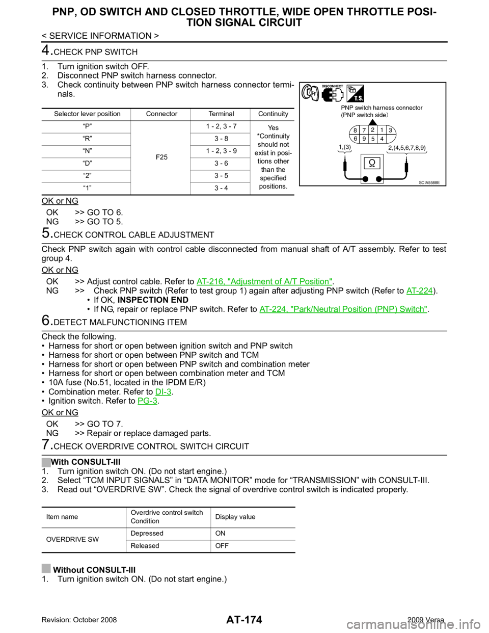
3. Check continuity between PNP switch harness connector termi- nals.
OK or NG OK >> GO TO 6.
NG >> GO TO 5. 5.
CHECK CONTROL CABLE ADJUSTMENT
Check PNP switch again with control cable disconnected from manual shaft of A/T assembly. Refer to test
group 4.
OK or NG OK >> Adjust control cable. Refer to
AT-216, " Adjustment of A/T Position " .
NG >> Check PNP switch (Refer to test group 1) again after adjusting PNP switch (Refer to AT-224 ).
• If OK, INSPECTION END
• If NG, repair or replace PNP switch. Refer to AT-224, " Park/Neutral Position (PNP) Switch " .
6.
DETECT MALFUNCTIONING ITEM
Check the following.
• Harness for short or open between ignition switch and PNP switch
• Harness for short or open between PNP switch and TCM
• Harness for short or open between PNP switch and combination meter
• Harness for short or open between combination meter and TCM
• 10A fuse (No.51, located in the IPDM E/R)
• Combination meter. Refer to DI-3 .
• Ignition switch. Refer to PG-3 .
OK or NG OK >> GO TO 7.
NG >> Repair or replace damaged parts. 7.
CHECK OVERDRIVE CONTROL SWITCH CIRCUIT
With CONSULT-III
1. Turn ignition switch ON. (Do not start engine.)
2. Select “TCM INPUT SIGNALS” in “DATA MONITO R” mode for “TRANSMISSION” with CONSULT-III.
3. Read out “OVERDRIVE SW”. Check the signal of ov erdrive control switch is indicated properly.
Without CONSULT-III
1. Turn ignition switch ON. (Do not start engine.) Selector lever position Connector Terminal Continuity
“P”
F251 - 2, 3 - 7
Yes
*Continuity
should not
exist in posi-
tions other than the
specified
positions.
“R” 3 - 8
“N” 1 - 2, 3 - 9
“D” 3 - 6 “2” 3 - 5
“1” 3 - 4 SCIA5588E
Item name
Overdrive control switch
Condition Display value
OVERDRIVE SW Depressed ON
Released OFF
Page 181 of 4331
AT-176< SERVICE INFORMATION >
PNP, OD SWITCH AND CLOSED THRO
TTLE, WIDE OPEN THROTTLE POSI-
TION SIGNAL CIRCUIT 11.
PERFORM SELF-DIAGNOSIS
Without CONSULT-III
Perform self-diagnosis. Refer to AT-83, " Diagnosis Procedure without CONSULT-III " .
OK or NG OK >>
INSPECTION END
NG − 1 >> Self-diagnosis does not activate: GO TO 12.
NG − 2 >> DTC is displayed: Check the malfunctioning system. Refer to AT-83, " Diagnosis Procedure with-
out CONSULT-III " .
12.
CHECK TCM
1. Check TCM input/output signal. Refer to AT-77, " TCM Terminal and Reference Value " .
2. If NG, recheck TCM pin terminals for damage or loose connection with harness connector.
OK or NG OK >>
INSPECTION END
NG >> Repair or replace damaged parts.
Component Inspection INFOID:0000000004305467
OVERDRIVE CONTROL SWITCH
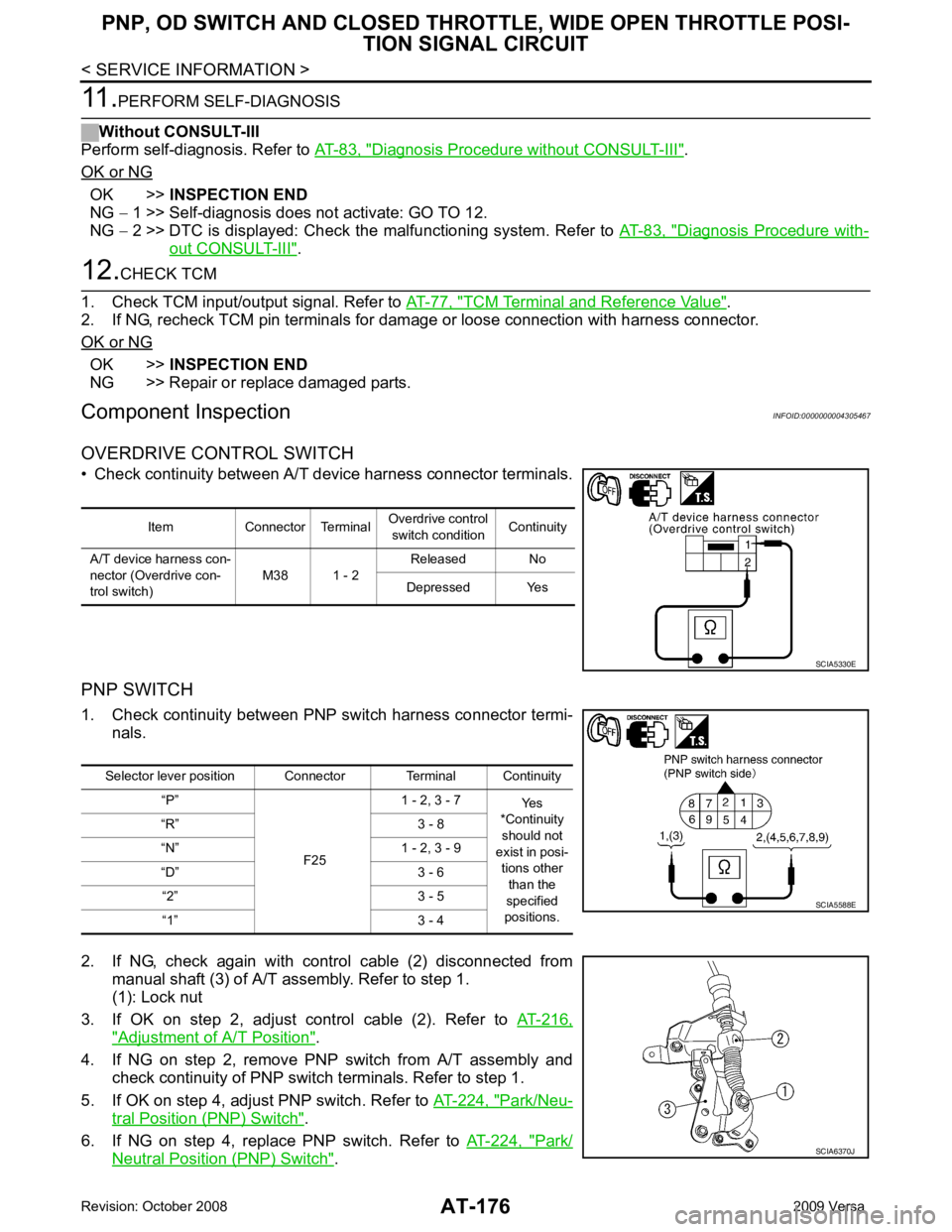
• Check continuity between A/T device harness connector terminals.
PNP SWITCH
1. Check continuity between PNP switch harness connector termi- nals.
2. If NG, check again with control cable (2) disconnected from manual shaft (3) of A/T assembly. Refer to step 1.
(1): Lock nut
3. If OK on step 2, adjust control cable (2). Refer to AT-216," Adjustment of A/T Position " .
4. If NG on step 2, remove PNP switch from A/T assembly and check continuity of PNP switch terminals. Refer to step 1.
5. If OK on step 4, adjust PNP switch. Refer to AT-224, " Park/Neu-
tral Position (PNP) Switch " .
6. If NG on step 4, replace PNP switch. Refer to AT-224, " Park/
Neutral Position (PNP) Switch " .Item Connector Terminal
Overdrive control
switch condition Continuity
A/T device harness con-
nector (Overdrive con-
trol switch) M38 1 - 2Released No
Depressed Yes SCIA5330E
Selector lever position Connector Terminal Continuity
“P”
F251 - 2, 3 - 7
Yes
*Continuity
should not
exist in posi- tions other
than the
specified
positions.
“R” 3 - 8
“N” 1 - 2, 3 - 9
“D” 3 - 6 “2” 3 - 5
“1” 3 - 4 SCIA5588E
SCIA6370J
Page 182 of 4331
AT
N
O P
SHIFT POSITION INDICATOR CIRCUIT
Description INFOID:0000000004305468
TCM sends the switch signals to combination meter vi a CAN communication line. Then selector lever position
is indicated on the shift position indicator.
CONSULT-III Reference Val ue in Data Monitor Mode INFOID:0000000004305469
Diagnosis Procedure INFOID:0000000004305470OK >>
INSPECTION END
NG >> Check the following.
SHIFT POSITION INDICATOR SYMPTOM CHART Item name Condition Display value
SLCT LVR POSI When setting selector lever to “N” or “P” positions. N · P
When setting selector lever to “R” position. R
When setting selector lever to “D” position. D
When setting selector lever to “2” position. 2
When setting selector lever to “1” position. 1 Items Presumed location of trouble
Actual position does not change. Park/neutral position (PNP) switch
• Refer to AT-91 .
A/T main system (Fail-safe function actuated)
• Refer to AT-79, " CONSULT-III Function (TRANSMISSION) " and
AT-83, " Diagnosis Procedure without CONSULT-III " .
Shift position indicator in the combination meter does not indicate
any position. Perform the self-diagnosis for A/T and the combination meter.
• Refer to AT-79, " CONSULT-III Function (TRANSMISSION) " and
DI-3 .
Actual position changes, but the shift position indicator in the com-
bination meter does not change.
Actual position differs from the shift position indicator in the com-
bination meter.
Shift position indicator in the combination meter does not indicate
specific position only. Check the combination meter.
• Refer to DI-3 .
Page 204 of 4331
TROUBLE DIAGNOSIS FOR SYMPTOMS
AT-199
< SERVICE INFORMATION >
D
E
F
G H
I
J
K L
M A
B AT
N
O P
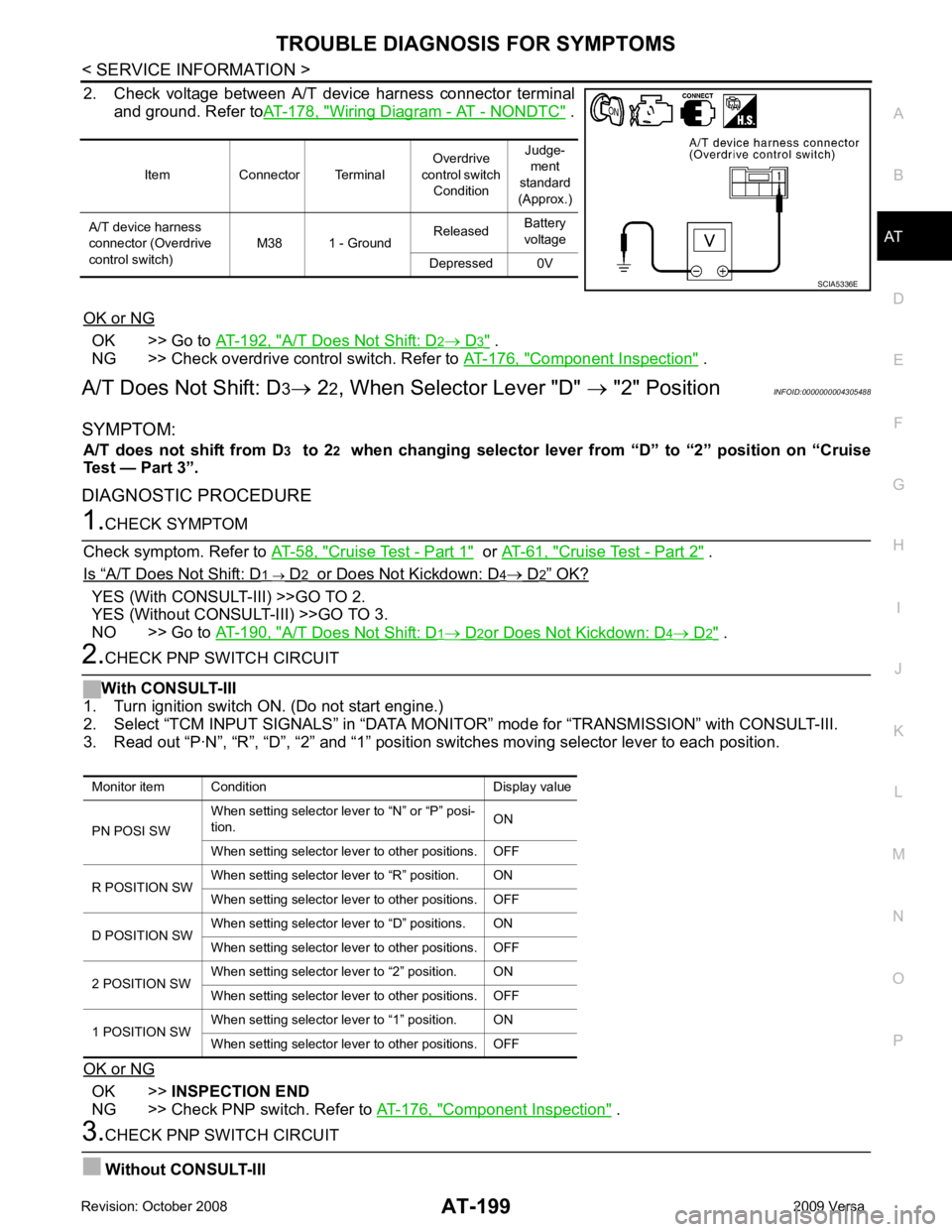
2. Check voltage between A/T device harness connector terminal
and ground. Refer to AT-178, " Wiring Diagram - AT - NONDTC " .
OK or NG OK >> Go to
AT-192, " A/T Does Not Shift: D 2 → D 3 " .
NG >> Check overdrive control switch. Refer to AT-176, " Component Inspection " .
A/T Does Not Shift: D 3→ 22, When Selector Lever "D" → "2" Position INFOID:0000000004305488
SYMPTOM: A/T does not shift from D 3 to 2 2 when changing selector lever from “D” to “2” position on “Cruise
Test — Part 3”.
DIAGNOSTIC PROCEDURE 1.
CHECK SYMPTOM
Check symptom. Refer to AT-58, " Cruise Test - Part 1 " or
AT-61, " Cruise Test - Part 2 " .
Is “ A/T Does Not Shift: D 1 → D 2 or Does Not Kickdown: D 4 → D 2 ” OK?
YES (With CONSULT-III) >>GO TO 2.
YES (Without CONSULT-III) >>GO TO 3.
NO >> Go to AT-190, " A/T Does Not Shift: D 1 → D 2 or Does Not Kickdown: D 4 → D 2 " .
2.
CHECK PNP SWITCH CIRCUIT
With CONSULT-III
1. Turn ignition switch ON. (Do not start engine.)
2. Select “TCM INPUT SIGNALS” in “DATA MONI TOR” mode for “TRANSMISSION” with CONSULT-III.
3. Read out “P·N”, “R”, “D”, “2” and “1” position switches moving selector lever to each position.
OK or NG OK >>
INSPECTION END
NG >> Check PNP switch. Refer to AT-176, " Component Inspection " .
3.
CHECK PNP SWITCH CIRCUIT
Without CONSULT-III Item Connector Terminal
Overdrive
control switch Condition Judge-
ment
standard
(Approx.)
A/T device harness
connector (Overdrive
control switch) M38 1 - Ground
Released
Battery
voltage
Depressed 0V SCIA5336E
Monitor item Condition Display value
PN POSI SW When setting selector le
ver to “N” or “P” posi-
tion. ON
When setting selector lever to other positions. OFF
R POSITION SW When setting selector lever to “R” position. ON
When setting selector lever to other positions. OFF
D POSITION SW When setting selector lever to “D” positions. ON
When setting selector lever to other positions. OFF
2 POSITION SW When setting selector lever to “2” position. ON
When setting selector lever to other positions. OFF
1 POSITION SW When setting selector lever to “1” position. ON
When setting selector lever to other positions. OFF
Page 205 of 4331
AT-200< SERVICE INFORMATION >
TROUBLE DIAGNOSIS FOR SYMPTOMS
1. Turn ignition switch ON. (Do not start engine.)
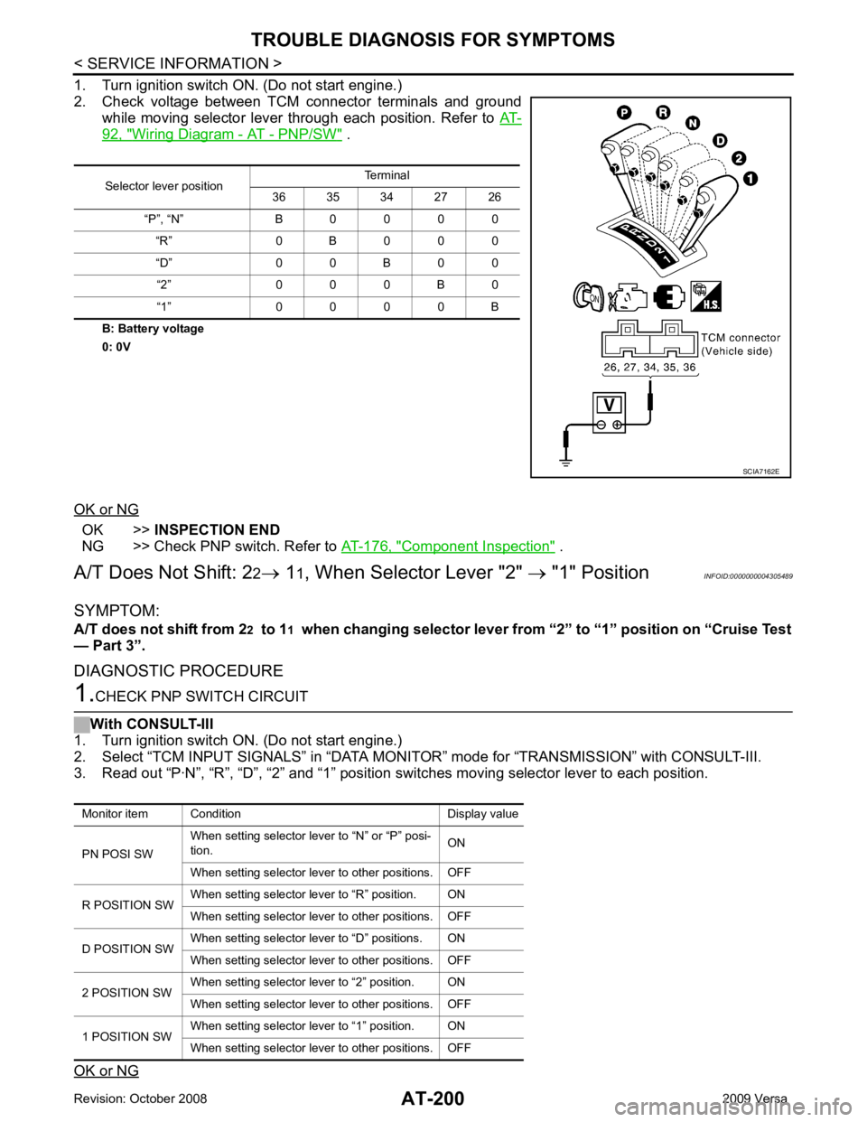
2. Check voltage between TCM connector terminals and ground while moving selector lever through each position. Refer to AT-92, " Wiring Diagram - AT - PNP/SW " .
B: Battery voltage
0: 0V
OK or NG OK >>
INSPECTION END
NG >> Check PNP switch. Refer to AT-176, " Component Inspection " .
A/T Does Not Shift: 2 2→ 11, When Selector Lever "2" → "1" Position INFOID:0000000004305489
SYMPTOM:
A/T does not shift from 2 2 to 1 1 when changing selector lever from “2” to “1” position on “Cruise Test
— Part 3”.
DIAGNOSTIC PROCEDURE 1.
CHECK PNP SWITCH CIRCUIT
With CONSULT-III
1. Turn ignition switch ON. (Do not start engine.)
2. Select “TCM INPUT SIGNALS” in “DATA MONITO R” mode for “TRANSMISSION” with CONSULT-III.
3. Read out “P·N”, “R”, “D”, “2” and “1” position switches moving selector lever to each position.
OK or NG Selector lever position
Terminal
36 35 34 27 26
“P”, “N” B 0 0 0 0 “R” 0 B 0 0 0
“D” 0 0 B 0 0 “2” 0 0 0 B 0
“1” 0 0 0 0 B SCIA7162E
Monitor item Condition Display value
PN POSI SW When setting selector le
ver to “N” or “P” posi-
tion. ON
When setting selector lever to other positions. OFF
R POSITION SW When setting selector lever to “R” position. ON
When setting selector lever to other positions. OFF
D POSITION SW When setting selector lever to “D” positions. ON
When setting selector lever to other positions. OFF
2 POSITION SW When setting selector lever to “2” position. ON
When setting selector lever to other positions. OFF
1 POSITION SW When setting selector lever to “1” position. ON
When setting selector lever to other positions. OFF
Page 208 of 4331
TROUBLE DIAGNOSIS FOR SYMPTOMS
AT-203
< SERVICE INFORMATION >
D
E
F
G H
I
J
K L
M A
B AT
N
O P
Without CONSULT-III
1. Turn ignition switch ON. (Do not start engine)
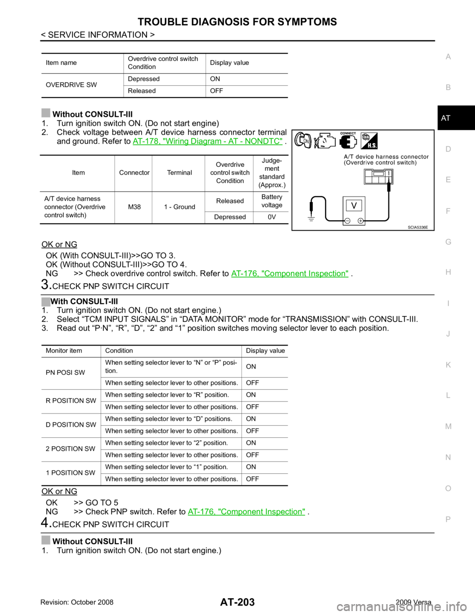
2. Check voltage between A/T device harness connector terminal and ground. Refer to AT-178, " Wiring Diagram - AT - NONDTC " .
OK or NG OK (With CONSULT-III)>>GO TO 3.
OK (Without CONSULT-III)>>GO TO 4.
NG >> Check overdrive control switch. Refer to AT-176, " Component Inspection " .
3.
CHECK PNP SWITCH CIRCUIT
With CONSULT-III
1. Turn ignition switch ON. (Do not start engine.)
2. Select “TCM INPUT SIGNALS” in “DATA MONI TOR” mode for “TRANSMISSION” with CONSULT-III.
3. Read out “P·N”, “R”, “D”, “2” and “1” position switches moving selector lever to each position.
OK or NG OK >> GO TO 5
NG >> Check PNP switch. Refer to AT-176, " Component Inspection " .
4.
CHECK PNP SWITCH CIRCUIT
Without CONSULT-III
1. Turn ignition switch ON. (Do not start engine.) Item name
Overdrive control switch
Condition Display value
OVERDRIVE SW Depressed ON
Released OFF Item Connector Terminal
Overdrive
control switch Condition Judge-
ment
standard
(Approx.)
A/T device harness
connector (Overdrive
control switch) M38 1 - Ground
Released
Battery
voltage
Depressed 0V SCIA5336E
Monitor item Condition Display value
PN POSI SW When setting selector le
ver to “N” or “P” posi-
tion. ON
When setting selector lever to other positions. OFF
R POSITION SW When setting selector lever to “R” position. ON
When setting selector lever to other positions. OFF
D POSITION SW When setting selector lever to “D” positions. ON
When setting selector lever to other positions. OFF
2 POSITION SW When setting selector lever to “2” position. ON
When setting selector lever to other positions. OFF
1 POSITION SW When setting selector lever to “1” position. ON
When setting selector lever to other positions. OFF
Page 403 of 4331
AUDIO
AV-19
< SERVICE INFORMATION >
C
D E
F
G H
I
J
L
M A
B AV
N
O P
*1: With premium system
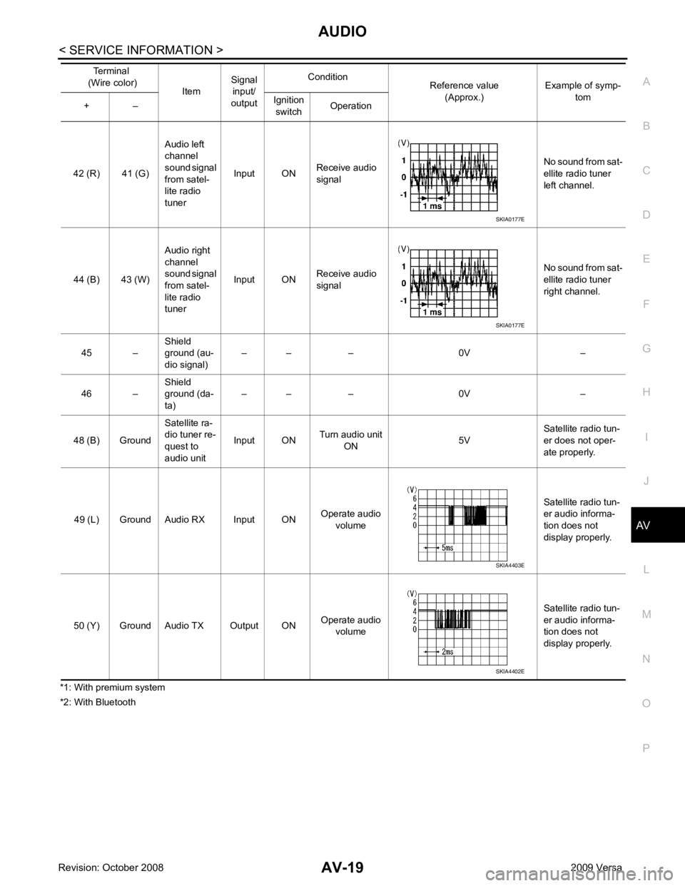
*2: With Bluetooth 42 (R) 41 (G)
Audio left
channel
sound signal
from satel-
lite radio
tuner Input ON
Receive audio
signal No sound from sat-
ellite radio tuner
left channel.
44 (B) 43 (W) Audio right
channel
sound signal
from satel-
lite radio
tuner Input ON
Receive audio
signal No sound from sat-
ellite radio tuner
right channel.
45 – Shield
ground (au-
dio signal) – – – 0V –
46 – Shield
ground (da-
ta) – – – 0V –
48 (B) Ground Satellite ra-
dio tuner re-
quest to
audio unit Input ON
Turn audio unit
ON 5VSatellite radio tun-
er does not oper-
ate properly.
49 (L) Ground Audio RX Input ON Operate audio
volume Satellite radio tun-
er audio informa-
tion does not
display properly.
50 (Y) Ground Audio TX Output ON Operate audio
volume Satellite radio tun-
er audio informa-
tion does not
display properly.
Terminal
(Wire color) ItemSignal
input/
output Condition
Reference value
(Approx.) Example of symp-
tom
+ – Ignition
switch Operation SKIA0177E
SKIA0177E
SKIA4403E
SKIA4402E
Page 419 of 4331
AV
N
O P
Sound Is Not Heard from Su
bwoofer (Premium System) INFOID:0000000004306978OK >> GO TO 2.
NG >> If fuse is blown, be sure to eliminate cause of blown fuse before installing new fuse. Refer to PG-3 .
YES >> GO TO 3.
NO >> Disconnect all audio unit harness connectors and wait for 2 minutes in order to reset the audio
unit. Reconnect audio unit connectors M44 and M45 first followed by M43 last. Repeat Steps 1
through 3 to confirm that "Woofer On" is now displayed. OK >> GO TO 4.
NG >> • Check connector housings for disconnected or loose terminals.
• Repair harness or connector. OK >> GO TO 5.
NG >> • Check connector housings for disconnected or loose terminals.
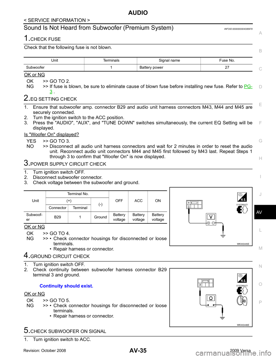
• Repair harness or connector. Unit
Terminal No.
OFF ACC ON
(+)
(-)
Connector Terminal
Subwoof-
er B29 1 Ground Battery
voltage Battery
voltage Battery
voltage