2009 NISSAN LATIO display
[x] Cancel search: displayPage 98 of 4331
AT
N
O P
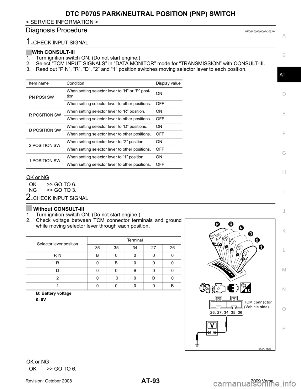
Diagnosis Procedure
INFOID:0000000004305344OK >> GO TO 6.
NG >> GO TO 3. OK >> GO TO 6.
Item name Condition Display value
PN POSI SW When setting selector le
ver to “N” or “P” posi-
tion. ON
When setting selector lever to other positions. OFF
R POSITION SW When setting selector lever to “R” position. ON
When setting selector lever to other positions. OFF
D POSITION SW When setting selector lever to “D” positions. ON
When setting selector lever to other positions. OFF
2 POSITION SW When setting selector lever to “2” position. ON
When setting selector lever to other positions. OFF
1 POSITION SW When setting selector lever to “1” position. ON
When setting selector lever to other positions. OFF Selector lever position
Terminal
36 35 34 27 26
P, N B 0 0 0 0 R 0 B 0 0 0
D 0 0 B 0 0 2 0 0 0 B 0
1 0 0 0 0 B
Page 101 of 4331
Diagnosis Procedure " .
WITH GST
Follow the procedure “With CONSULT-III”. Item name Condition Display value (Approx.)
FLUID TEMP SE When A/T fluid temperature is 20
°C (68 °F). 1.5 V
When A/T fluid temperature is 80 °C (176 °F). 0.5 V
Page 106 of 4331
AT
N
O P
DTC P0720 VEHICLE SPEED SENS
OR A/T (REVOLUTION SENSOR)
Description INFOID:0000000004305354
The revolution sensor detects the revolution of the id ler gear parking pawl lock gear and emits a pulse signal.
The pulse signal is sent to the TCM which converts it into vehicle speed.
CONSULT-III Reference Val ue in Data Monitor Mode INFOID:0000000004305355
Remarks: Specification data are reference values.
On Board Diagnosis Logic INFOID:0000000004305356
• This is an OBD-II self-diagnostic item.
• Diagnostic trouble code “P0720 VHCL SPEED SEN-AT” with CONSULT-III or 1st judgement flicker without
CONSULT-III is detected when TCM does not rece ive the proper voltage signal from the sensor.
Possible Cause INFOID:0000000004305357
• Harness or connector (The sensor circuit is open or shorted.)
• Revolution sensor
DTC Confirmation Procedure INFOID:0000000004305358
CAUTION:
• Always drive vehicle at a safe speed.
• Be careful not to rev engine into the red zone on the tachometer.
• If performing this “DTC Confirmation Procedure” again, always turn ignition switch OFF and wait at
least 10 seconds before continuing.
After the repair, perform the following procedure to confirm the malfunction is eliminated.
WITH CONSULT-III
1. Turn ignition switch ON and select “DATA MO NITOR” mode for “TRANSMISSION” with CONSULT-III.
2. Touch “START”.
3. Drive vehicle and check for an in crease of “VHCL/S SE-MTR” value.
If the check result is NG, go to AT-103, " Diagnosis Procedure " .
If the check result is OK, go to following step.
4. Select “DATA MONITOR” mode for “TRANSMISSION” with CONSULT-III.
5. Touch “START”.
6. Start engine and maintain the following conditions for at least 5 consecutive seconds. VEHICLE SPEED: 30 km/h (19 MPH) or more
THROTTLE POSI: More than 1.0/8
SLCT LVR POSI: “D” position
Driving location: Driving the vehic le uphill (increased engine load) will help maintain the driving
conditions required for this test.
If the check result is NG, go to AT-103, " Diagnosis Procedure " .
If the check result is OK, go to following step.
7. Maintain the following conditions for at least 5 consecutive seconds. ENGINE SPEED: 3,500 rpm or more
THROTTLE POSI: More than 1.0/8
SLCT LVR POSI: “D” position
Driving location: Driving the vehic le uphill (increased engine load) will help maintain the driving
conditions required for this test.
WITH GST
Follow the procedure “WITH CONSULT-III”.
WITHOUT CONSULT-III
1. Start engine. Item name Condition Display value
VHCL/S SE-A/T During driving Approxima tely matches the speedometer reading.
Page 111 of 4331
Diagnosis Procedure " .
WITH GST
Follow the procedure “WITH CONSULT-III”.
WITHOUT CONSULT-III
1. Start engine.
2. Drive vehicle under the following conditions for more than 10 seconds.
Selector lever position: “D” position
Vehicle speed: Higher than 10 km/h (6 MPH)
Throttle position: Greater than 1. 0/8 of the full throttle position
3. Perform self-diagnosis. Refer to AT-83, " Diagnosis Procedure without CONSULT-III " .
4. If the check result is NG, go to AT-108, " Diagnosis Procedure " .
Item name Condition Display value
ENGINE SPEED Engine running Approximately matches the tachometer reading.
Page 113 of 4331
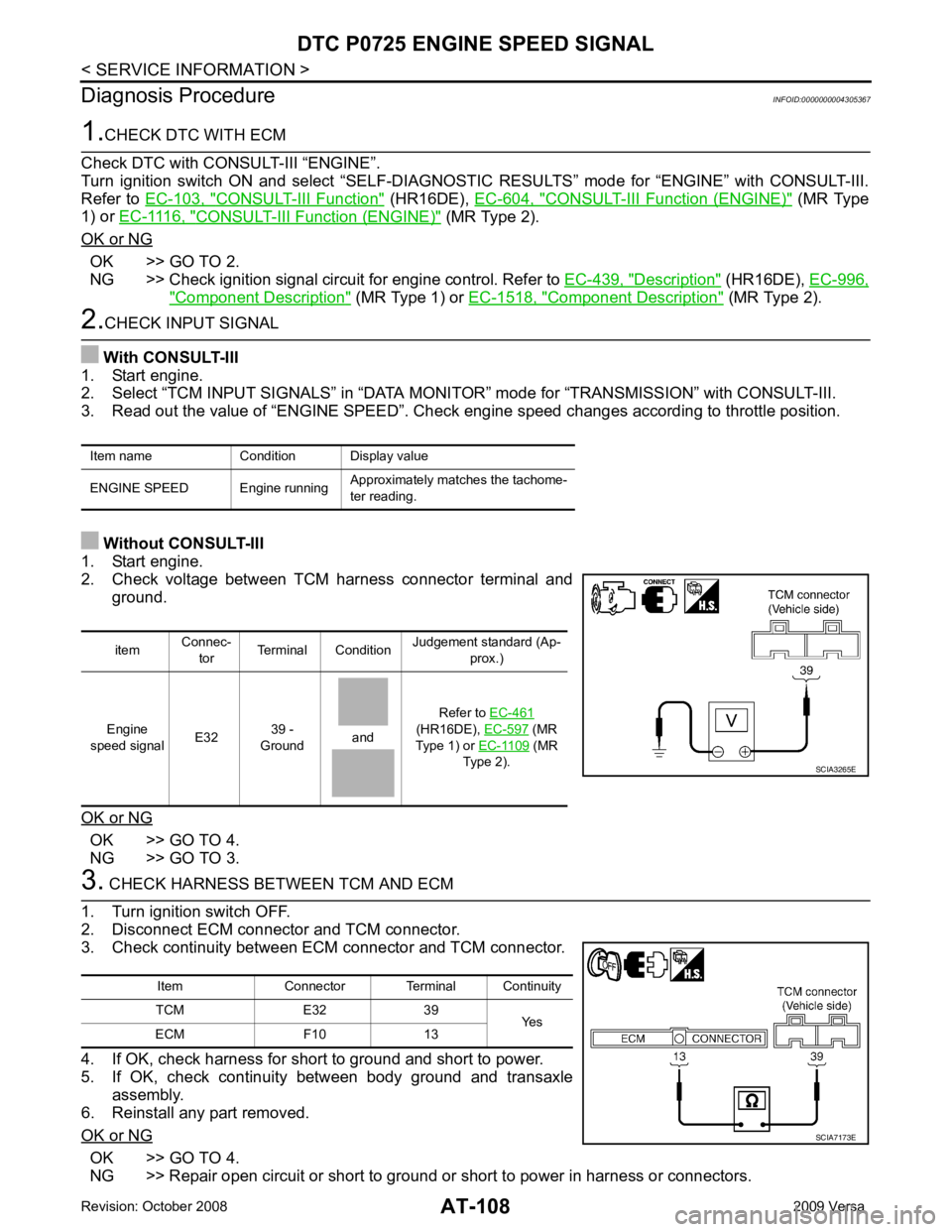
CONSULT-III Function " (HR16DE),
EC-604, " CONSULT-III Function (ENGINE) " (MR Type
1) or EC-1116, " CONSULT-III Function (ENGINE) " (MR Type 2).
OK or NG OK >> GO TO 2.
NG >> Check ignition signal circuit for engine control. Refer to EC-439, " Description " (HR16DE),
EC-996, " Component Description " (MR Type 1) or
EC-1518, " Component Description " (MR Type 2).
OK >> GO TO 4.
NG >> GO TO 3. OK >> GO TO 4.
NG >> Repair open circuit or short to ground or short to power in harness or connectors.
Item name Condition Display value
ENGINE SPEED Engine running Approximately matches the tachome-
ter reading. item
Connec-
tor Terminal Condition
Judgement standard (Ap-
prox.)
Engine
speed signal E32
39 -
Ground
and Refer to
EC-461
(HR16DE), EC-597 (MR
Type 1) or EC-1109 (MR
Type 2).
Page 116 of 4331
AT
N
O P
5. Accelerate vehicle to 20 to 25 km/h (12 to 16 MPH) under the following conditions and release the accel-
erator pedal completely.
THROTTLE POSI: Less th an 1.0/8 (at all times during step 4)
SLCT LVR POSI: “D” position
- Make sure that “GEAR” shows “2” after releasing pedal.
6. Depress accelerator pedal to WOT (more than 7.0/ 8 of “THROTTLE POSI”) quickly from a speed of 20 to
25 km/h (12 to 16 MPH) until “TESTING” changes to “STOP VEHICLE” or “COMPLETED”. (It will take
approximately 3 seconds.)
If the check result NG appears on CONSULT-III screen, go to AT-111, " Diagnosis Procedure " .
If “STOP VEHICLE” appears on CONSULT-III screen, go to the following step.
- Make sure that “GEAR” shows “1” when depressing accelerator pedal to WOT.
- If “TESTING” does not appear on CONSULT-III fo r a long time, select “SELF-DIAG RESULTS” for
“TRANSMISSION”. In case a DTC other than “P0731 A/T 1ST GR FNCTN” is shown, refer to AT-79," CONSULT-III Function (TRANSMISSION) " .
7. Stop vehicle.
8. Follow the instruction displayed. (Check for normal shifting referring to the table below.)
9. Make sure that “OK” is disp layed. (If “NG” is displayed, refer to “Diagnostic Procedure”.)
Refer to AT-111, " Diagnosis Procedure " .
Refer to AT-64, " Vehicle Speed at Which Gear Shifting Occurs " .
WITH GST
Follow the procedure “WITH CONSULT-III”.
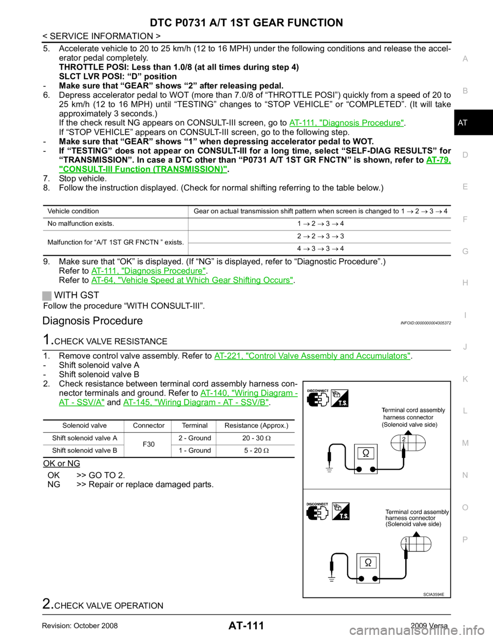
Diagnosis Procedure INFOID:0000000004305372Control Valve Assembly and Accumulators " .
- Shift solenoid valve A
- Shift solenoid valve B
2. Check resistance between terminal cord assembly harness con- nector terminals and ground. Refer to AT-140, " Wiring Diagram -
AT - SSV/A " and
AT-145, " Wiring Diagram - AT - SSV/B " .
OK or NG OK >> GO TO 2.
NG >> Repair or replace damaged parts. Solenoid valve Connector Terminal Resistance (Approx.)
Shift solenoid valve A F302 - Ground 20 - 30
Ω
Shift solenoid valve B 1 - Ground 5 - 20 Ω
Page 119 of 4331
Diagnosis Procedure " .
If “STOP VEHICLE” appears on CONSUL T-III screen, go to following step.
- Make sure that “GEAR” shows “2” wh en depressing accelerator pedal to WOT.
- If “TESTING” does not appear on CONSULT-III fo r a long time, select “SELF-DIAG RESULTS” for
“TRANSMISSION”. In case a DTC other than “P0732 A/T 2ND GR FNCTN” is shown, refer to AT-79," CONSULT-III Function (TRANSMISSION) " .
7. Stop vehicle.
8. Follow the instruction displayed. (Check for normal shifting referring to the table below.)
9. Make sure that “OK” is displayed. (If “NG” is displayed, refer to “Diagnostic Procedure”.)
Refer to AT-114, " Diagnosis Procedure " .
Refer to AT-64, " Vehicle Speed at Which Gear Shifting Occurs " .
WITH GST
Follow the procedure “WITH CONSULT-III”.
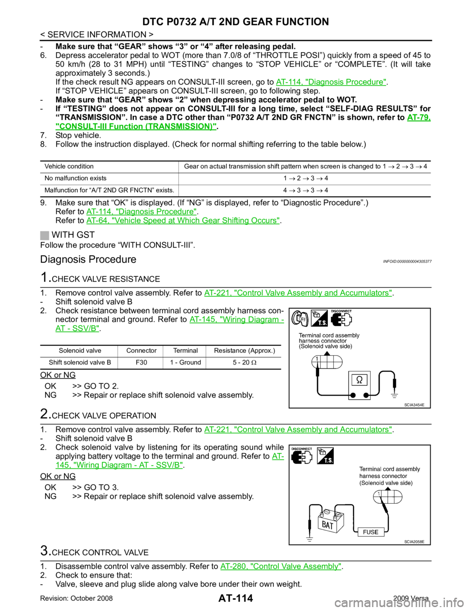
Diagnosis Procedure INFOID:0000000004305377Control Valve Assembly and Accumulators " .
- Shift solenoid valve B
2. Check resistance between terminal cord assembly harness con- nector terminal and ground. Refer to AT-145, " Wiring Diagram -
AT - SSV/B " .
OK or NG OK >> GO TO 2.
NG >> Repair or replace shift solenoid valve assembly. Control Valve Assembly and Accumulators " .
- Shift solenoid valve B
2. Check solenoid valve by listening for its operating sound while applying battery voltage to the terminal and ground. Refer to AT-145, " Wiring Diagram - AT - SSV/B " .
OK or NG OK >> GO TO 3.
NG >> Repair or replace shift solenoid valve assembly. Control Valve Assembly " .
2. Check to ensure that:
- Valve, sleeve and plug slide along valve bore under their own weight. Vehicle condition Gear on actual transmission shift pattern when screen is changed to 1
→ 2 → 3 → 4
No malfunction exists 1 → 2 → 3 → 4
Malfunction for “A/T 2ND GR FNCTN” exists. 4 → 3 → 3 → 4 Solenoid valve Connector Terminal Resistance (Approx.)
Shift solenoid valve B F30 1 - Ground 5 - 20 Ω SCIA2058E
Page 122 of 4331
DTC P0733 A/T 3RD GEAR FUNCTION
AT-117
< SERVICE INFORMATION >
D
E
F
G H
I
J
K L
M A
B AT
N
O P
-
Make sure that “GEAR” shows “4” after releasing pedal.
6. Depress accelerator pedal steadily with 3.5/8 - 4.5/ 8 of “THROTTLE POSI” from a speed of 60 to 75 km/h
(37 to 47 MPH) until “TESTING” changes to “STOP VE HICLE” or “COMPLETED”. (It will take approxi-
mately 3 seconds.)
If the check result NG appears on CONSULT-III screen, go to AT-117, " Diagnosis Procedure " .
If “STOP VEHICLE” appears on CONSULT-III screen, go to following step.
- Make sure that “GEAR” shows “3” when depr essing accelerator pedal with 3.5/8 - 4.5/8 of
“THROTTLE POSI”.
- If “TESTING” does not appear on CONSULT-III fo r a long time, select “SELF-DIAG RESULTS” for
“TRANSMISSION”. In case a DTC ot her than “P0733 A/T 3RD GR FNCTN” is shown, refer to AT-79," CONSULT-III Function (TRANSMISSION) " .
7. Stop vehicle.
8. Follow the instruction displayed. (Check for normal shifting referring to the table below.)
9. Make sure that “OK” is disp layed. (If “NG” is displayed, refer to “Diagnostic Procedure”.)
Refer to AT-117, " Diagnosis Procedure " .
Refer to AT-64, " Vehicle Speed at Which Gear Shifting Occurs " .
WITH GST
Follow the procedure “WITH CONSULT-III”.
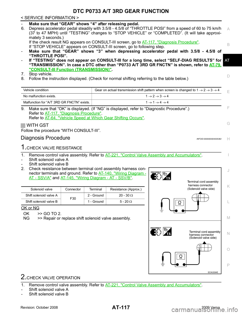
Diagnosis Procedure INFOID:00000000043053821.
CHECK VALVE RESISTANCE
1. Remove control valve assembly. Refer to AT-221, " Control Valve Assembly and Accumulators " .
- Shift solenoid valve A
- Shift solenoid valve B
2. Check resistance between terminal cord assembly harness con- nector terminals and ground. Refer to AT-140, " Wiring Diagram -
AT - SSV/A " and
AT-145, " Wiring Diagram - AT - SSV/B " .
OK or NG OK >> GO TO 2.
NG >> Repair or replace shift solenoid valve assembly. 2.
CHECK VALVE OPERATION
1. Remove control valve assembly. Refer to AT-221, " Control Valve Assembly and Accumulators " .
- Shift solenoid valve A
- Shift solenoid valve B Vehicle condition Gear on actual transmission shift pattern when screen is changed to 1
→ 2 → 3 → 4
No malfunction exists. 1 → 2 → 3 → 4
Malfunction for “A/T 3 RD GR FNCTN” exists. 1 → 1 → 4 → 4 Solenoid valve Connector Terminal Resistance (Approx.)
Shift solenoid valve A F302 - Ground 20 - 30
Ω
Shift solenoid valve B 1 - Ground 5 - 20 Ω SCIA3594E