2009 NISSAN LATIO coolant level
[x] Cancel search: coolant levelPage 2766 of 4331
![NISSAN LATIO 2009 Service Repair Manual EC-1410< SERVICE INFOMATION >
[MR TYPE 2]
DTC P1217 ENGINE
OVER TEMPERATURE
Never remove the radiator cap when the engine is hot. Serious burns could be caused by high pres-
sure flu NISSAN LATIO 2009 Service Repair Manual EC-1410< SERVICE INFOMATION >
[MR TYPE 2]
DTC P1217 ENGINE
OVER TEMPERATURE
Never remove the radiator cap when the engine is hot. Serious burns could be caused by high pres-
sure flu](/manual-img/5/57359/w960_57359-2765.png)
EC-1410< SERVICE INFOMATION >
[MR TYPE 2]
DTC P1217 ENGINE
OVER TEMPERATURE
Never remove the radiator cap when the engine is hot. Serious burns could be caused by high pres-
sure fluid escaping from the reser voir tank or the radiator.
Wrap a thick cloth around cap. Carefully remove the cap by turning it a quarter turn to allow built-up
pressure to escape. Then turn the cap all the way off.
WITH CONSULT-III
1. Check the coolant level in the reservoir tank and radiator. Allow engine to cool before checking coolant level.
If the coolant level in the reservoir tank and/or radiator is below
the proper range, skip the following steps and go to EC-1412," Diagnosis Procedure " or
EC-1412, " Diagnosis Procedure " .
2. Confirm whether customer filled the coolant or not. If customer
filled the coolant, skip the following steps and go to EC-1412," Diagnosis Procedure " or
EC-1412, " Diagnosis Procedure " .
3. Turn ignition switch ON.
4. Perform “COOLING FAN” in “ACTIVE TEST” mode with CON- SULT-III.
5. If the results are NG, go to EC-1412, " Diagnosis Procedure " or
EC-1412, " Diagnosis Procedure " .
WITH GST
1. Check the coolant level in the reservoir tank and radiator. Allow engine to cool before checking coolant level.
If the coolant level in the reservoir tank and/or radiator is below
the proper range, skip the following steps and go to EC-1412," Diagnosis Procedure " .
2. Confirm whether customer filled the coolant or not. If customer
filled the coolant, skip the following steps and go to EC-1412," Diagnosis Procedure " .
3. Perform IPDM/ER auto active te st and check cooling fan motor
operation. Refer to PG-19, " Auto Active Test " .
4. If NG, go to EC-1412, " Diagnosis Procedure " . SEF621W
SEF621W
Page 2771 of 4331
EC
NP
O
Cooling fan motor terminal 2 and IPDM E/R terminal 24.
Cooling fan motor terminal 3 and IPDM E/R terminal 23.
Cooling fan motor terminal 4 and ground.
Refer to wiring diagram.
3. Also check harness for short to ground and short to power.
OK or NG OK >> GO TO 15.
NG >> GO TO 14. Component Inspection " .
OK or NG OK >> GO TO 16.
NG >> Replace cooling fan motor. .
OK or NG OK >> Replace IPDM E/R. Refer to
PG-27, " Removal and Installation of IPDM E/R " .
NG >> Repair or replace harness or connector.
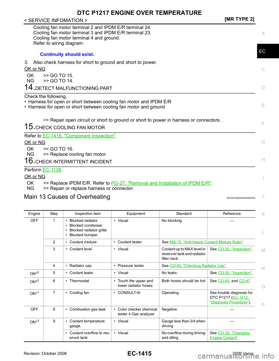
Main 13 Causes of Overheating INFOID:0000000004500285
Continuity should exist.
Engine Step Inspection item Equipment Standard Reference OFF 1 • Blocked radiator • Blocked condenser
• Blocked radiator grille
• Blocked bumper • Visual No blocking —
2 • Coolant mixture • Coolant tester See MA-15, " Anti-freeze Coolant Mixture Ratio " .
3 • Coolant level • Visual Coolant up to MAX level in reservoir tank and radiator
filler neck See
CO-35, " Inspection " .
4 • Radiator cap • Pressure tester See CO-40, " Checking Radiator Cap " .
ON* 2
5 • Coolant leaks • Visual No leaks See CO-35, " Inspection " .
ON* 2
6 • Thermostat • Touch the upper and
lower radiator hosesBoth hoses should be hot See
CO-45 , and
CO-47 ON*
1
7 • Cooling fan • CONSULT-III Operating See trouble diagnosis for
DTC P1217 (EC-1412, " Diagnosis Procedure " ).
OFF 8 • Combustion gas leak • Color checker chemical tester 4 Gas analyzerNegative —
ON* 3
9 • Coolant temperature
gauge • Visual Gauge less than 3/4 when
driving —
• Coolant overflow to res- ervoir tank • Visual No overflow during driving
and idling See
CO-35, " Changing
Engine Coolant " .
Page 2772 of 4331
![NISSAN LATIO 2009 Service Repair Manual EC-1416< SERVICE INFOMATION >
[MR TYPE 2]
DTC P1217 ENGINE
OVER TEMPERATURE
*1: Turn the ignition switch ON.
*2: Engine running at 3,000 rpm for 10 minutes.
*3: Drive at 90 km/h (55 MPH) for 30 minut NISSAN LATIO 2009 Service Repair Manual EC-1416< SERVICE INFOMATION >
[MR TYPE 2]
DTC P1217 ENGINE
OVER TEMPERATURE
*1: Turn the ignition switch ON.
*2: Engine running at 3,000 rpm for 10 minutes.
*3: Drive at 90 km/h (55 MPH) for 30 minut](/manual-img/5/57359/w960_57359-2771.png)
EC-1416< SERVICE INFOMATION >
[MR TYPE 2]
DTC P1217 ENGINE
OVER TEMPERATURE
*1: Turn the ignition switch ON.
*2: Engine running at 3,000 rpm for 10 minutes.
*3: Drive at 90 km/h (55 MPH) for 30 minutes and then let idle for 10 minutes.
*4: After 60 minutes of cool down time.
For more informat ion, refer to CO-32 .
Component Inspection INFOID:0000000004500286
COOLING FAN MOTOR
Model with A/C
1. Disconnect cooling fan motor harness connectors.
2. Supply cooling fan motor terminals with battery voltage and check operation.
Cooling fan motor should operate.
If NG, replace cooling fan motor.
Models without A/C
1. Disconnect cooling fan motor harness connectors.
2. Supply cooling fan motor terminals with battery voltage and check operation.
Cooling fan motor should operate.
If NG, replace cooling fan motor. OFF*
4
10 • Coolant return from res-
ervoir tank to radiator • Visual Should be initial level in
reservoir tank See
CO-35, " Inspection " .
OFF 11 • Water control valve • Remove and inspect
the valve Within the specified value See
CO-47, " Removal
and Installation "
OFF 12 • Cylinder head • Straight gauge feeler
gauge0.1 mm (0.004 in) Maxi-
mum distortion (warping) See
EM-185 .
13 • Cylinder block and pis- tons • Visual No scuffing on cylinder
walls or piston See
EM-199 .
Engine Step Inspection item Equipment Standard Reference Terminals
(+) (-)
Cooling fan motor 1 2 SEF888V
Speed
terminals
(+) ( −)
Cooling fan motor Low 1 4
2 3
High 1 and 2 3 and 4 SEF734W
Page 3004 of 4331
EM
NP
O
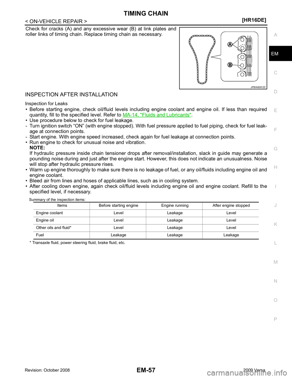
Check for cracks (A) and any excessive wear (B) at link plates and
roller links of timing chain. Replace timing chain as necessary.
INSPECTION AFTER INSTALLATION
Inspection for Leaks • Before starting engine, check oil/fluid levels incl uding engine coolant and engine oil. If less than required
quantity, fill to the specified level. Refer to MA-14, " Fluids and Lubricants " .
• Use procedure below to check for fuel leakage.
- Turn ignition switch “ON” (with engine stopped). With fuel pressure applied to fuel piping, check for fuel leak-
age at connection points.
- Start engine. With engine speed increased, check again for fuel leakage at connection points.
• Run engine to check for unusual noise and vibration. NOTE:
If hydraulic pressure inside chain tensioner drops after removal/installation, slack in guide may generate a
pounding noise during and just after the engine start. However, this does not indicate an unusualness. Noise
will stop after hydraulic pressure rises.
• Warm up engine thoroughly to make sure there is no leak age of fuel, or any oil/fluids including engine oil and
engine coolant.
• Bleed air from lines and hoses of applicable lines, such as in cooling system.
• After cooling down engine, again check oil/fluid levels including engine oil and engine coolant. Refill to the specified level, if necessary.
Summary of the inspection items:
* Transaxle fluid, power steering fluid, brake fluid, etc.
Page 3021 of 4331
Fluids and Lubricants " .
• Use procedure below to check for fuel leakage.
- Turn ignition switch “ON” (with engine stopped). With fuel pressure applied to fuel piping, check for fuel leak-
age at connection points.
- Start engine. With engine speed increased, che ck again for fuel leakage at connection points.
• Run engine to check for unusual noise and vibration. NOTE:
If hydraulic pressure inside timing chain tensioner drops after removal/installation, slack in the guide may
generate a pounding noise during and just after engine start. However, this is normal. Noise will stop after
hydraulic pressure rises.
• Warm up engine thoroughly to make sure there is no leakage of fuel, or any oil/fluids including engine oil and
engine coolant.
• Bleed air from lines and hoses of applicable lines, such as in cooling system.
• After cooling down engine, again check oil/fluid levels including engine oil and engine coolant. Refill to the
specified level, if necessary.
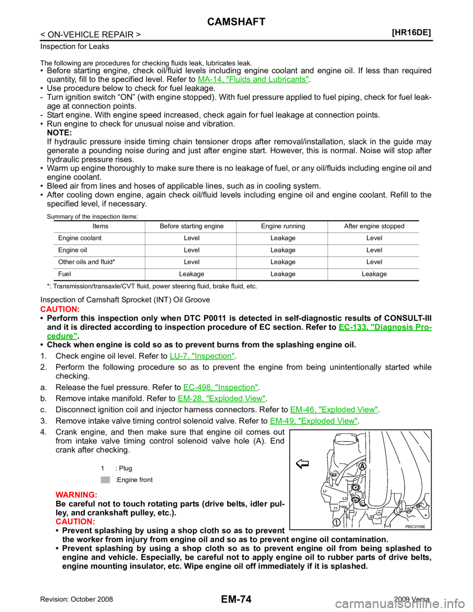
Summary of the inspection items:
*: Transmission/transaxle/CVT fluid, power steering fluid, brake fluid, etc.
Inspection of Camshaft Sprocket (INT) Oil Groove
CAUTION:
• Perform this inspection only when DTC P0011 is de tected in self-diagnostic results of CONSULT-III
and it is directed according to inspect ion procedure of EC section. Refer to EC-133, " Diagnosis Pro-
cedure " .
• Check when engine is cold so as to pr event burns from the splashing engine oil.
1. Check engine oil level. Refer to LU-7, " Inspection " .
2. Perform the following procedure so as to prevent the engine from being unintentionally started while
checking.
a. Release the fuel pressure. Refer to EC-498, " Inspection " .
b. Remove intake manifold. Refer to EM-28, " Exploded View " .
c. Disconnect ignition coil and injector harness connectors. Refer to EM-46, " Exploded View " .
3. Remove intake valve timing control solenoid valve. Refer to EM-49, " Exploded View " .
4. Crank engine, and then make sure that engine oil comes out from intake valve timing control solenoid valve hole (A). End
crank after checking.
WARNING:
Be careful not to touch rotating parts (drive belts, idler pul-
ley, and crankshaft pulley, etc.).
CAUTION:
• Prevent splashing by using a shop cloth so as to prevent
the worker from injury from engine oil an d so as to prevent engine oil contamination.
• Prevent splashing by using a shop cloth so as to prevent engine oil from being splashed to
engine and vehicle. Especially, be careful not to apply engine oil to rubber parts of drive belts,
engine mounting insulator, etc. Wipe engi ne oil off immediately if it is splashed.
Items Before starting engine Engine running After engine stopped
Engine coolant Level Leakage Level
Engine oil Level Leakage Level
Other oils and fluid* Level Leakage Level
Fuel Leakage Leakage Leakage 1 : Plug
:Engine front
Page 3028 of 4331
![NISSAN LATIO 2009 Service Repair Manual CYLINDER HEAD
EM-81
< ON-VEHICLE REPAIR >
[HR16DE] C
D E
F
G H
I
J
K L
M A EM
NP
O
2. Tighten cylinder head bolts in numer
ical order as shown with the
following procedure to install cylinder head.
CA NISSAN LATIO 2009 Service Repair Manual CYLINDER HEAD
EM-81
< ON-VEHICLE REPAIR >
[HR16DE] C
D E
F
G H
I
J
K L
M A EM
NP
O
2. Tighten cylinder head bolts in numer
ical order as shown with the
following procedure to install cylinder head.
CA](/manual-img/5/57359/w960_57359-3027.png)
CYLINDER HEAD
EM-81
< ON-VEHICLE REPAIR >
[HR16DE] C
D E
F
G H
I
J
K L
M A EM
NP
O
2. Tighten cylinder head bolts in numer
ical order as shown with the
following procedure to install cylinder head.
CAUTION:
If cylinder head bolts are re -used, check their outer diame-
ters before installation. Fol low the “Cylinder Head Bolts
Outer Diameter” measurement procedure.
a. Apply new engine oil to threads and seating surfaces of bolts.
b. Tighten all bolts in the specified order.
c. Turn all bolts 60 degrees clockwise (angle tightening) using Tool (A) in the specified order.
CAUTION:
Check and confirm the tightening angle by using Tool (A) or
protractor. Avoid judgment by visual inspection without the
tool.
d. Completely loosen all bolts in reverse order. CAUTION:
In this step, loosen bolts in reverse order of that indicated.
e. Tighten all bolts in the specified order.
f. Turn all bolts 75 degrees clockwise (angle tightening) using Tool (A) in the specified order.
CAUTION:
Check and confirm the tightening angle by using Tool (A) or
protractor. Avoid judgment by visual inspection without the
tool.
g. Turn all bolts 75 degrees clockwise again (angle tightening) using Tool (A) in the specified order.
CAUTION:
Check and confirm the tightening angle by using To ol (A) or protractor. Avoid judgment by visual
inspection without the tool.
3. Installation of the remaining components is in the reverse order of removal.
INSPECTION AFTER INSTALLATION
Inspection for Leaks • Before starting engine, check oil/fluid levels incl uding engine coolant and engine oil. If less than required
quantity, fill to the specified level. Refer to MA-14, " Fluids and Lubricants " .
A : EXH side
B : INT side
: Engine front
: 40.0 N·m (4.1 kg-m, 30 ft-lb)
Tool number : KV10112100 (BT-8653-A) PBIC3732E
PBIC3733E
: 0 N·m (0 kg-m, 0 ft-lb)
: 40.0 N·m (4.1 kg-m, 30 ft-lb)
Tool number : KV10112100 (BT-8653-A) PBIC3733E
Page 3038 of 4331
EM
NP
O
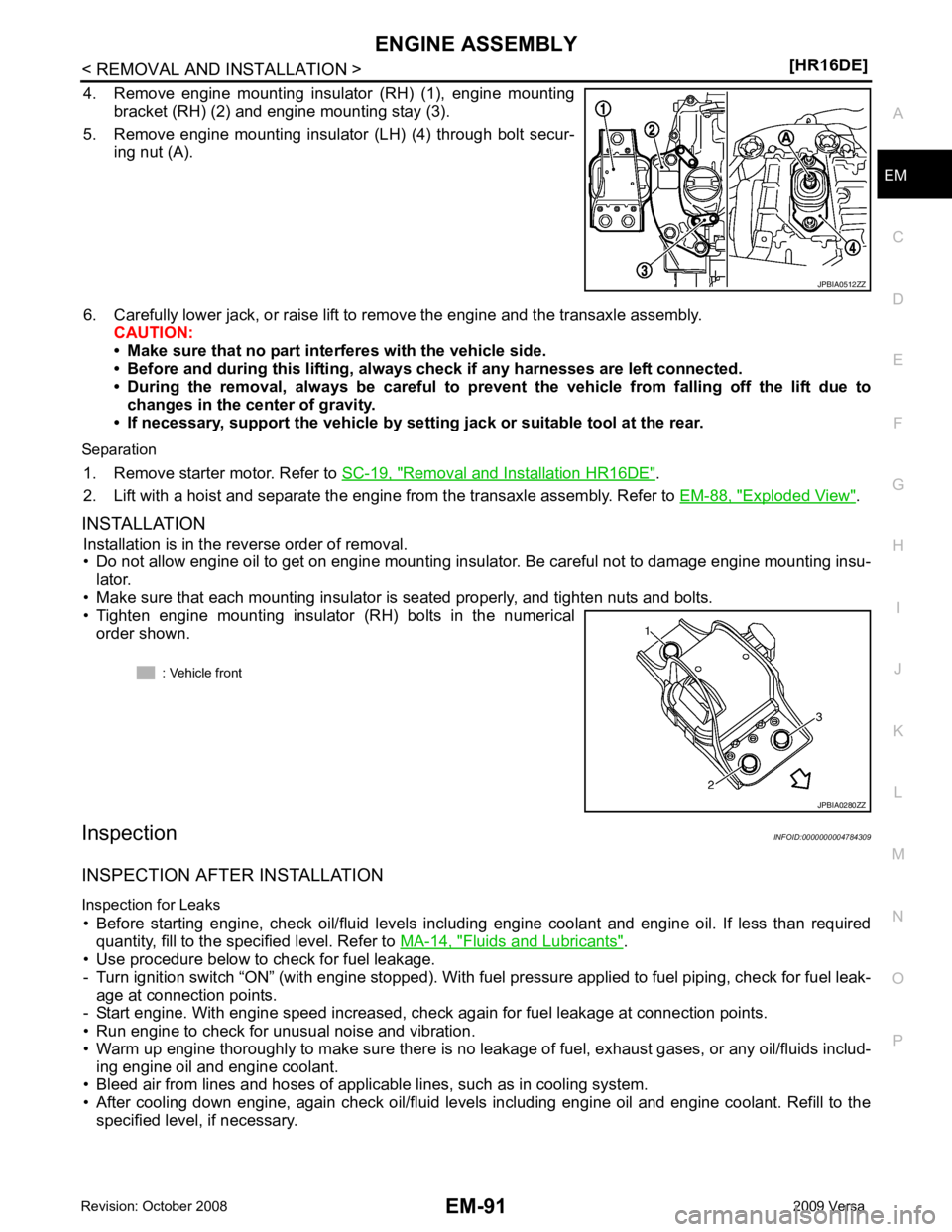
4. Remove engine mounting insulator (RH) (1), engine mounting
bracket (RH) (2) and engine mounting stay (3).
5. Remove engine mounting insulator (LH) (4) through bolt secur- ing nut (A).
6. Carefully lower jack, or raise lift to remove the engine and the transaxle assembly. CAUTION:
• Make sure that no part interferes with the vehicle side.
• Before and during this lifting, alw ays check if any harnesses are left connected.
• During the removal, always be careful to prevent the vehicle from falling off the lift due to
changes in the center of gravity.
• If necessary, support the vehicle by setting jack or suitable tool at the rear.
Separation 1. Remove starter motor. Refer to SC-19, " Removal and Installation HR16DE " .
2. Lift with a hoist and separate the engine from the transaxle assembly. Refer to EM-88, " Exploded View " .
INSTALLATION Installation is in the reverse order of removal.
• Do not allow engine oil to get on engine mounting insulator. Be careful not to damage engine mounting insu- lator.
• Make sure that each mounting insulator is seated properly, and tighten nuts and bolts.
• Tighten engine mounting insulator (RH) bolts in the numerical
order shown.
Inspection INFOID:0000000004784309
INSPECTION AFTER INSTALLATION
Inspection for Leaks • Before starting engine, check oil/fluid levels incl uding engine coolant and engine oil. If less than required
quantity, fill to the specified level. Refer to MA-14, " Fluids and Lubricants " .
• Use procedure below to check for fuel leakage.
- Turn ignition switch “ON” (with engine stopped). With fuel pressure applied to fuel piping, check for fuel leak-
age at connection points.
- Start engine. With engine speed increased, check again for fuel leakage at connection points.
• Run engine to check for unusual noise and vibration.
• Warm up engine thoroughly to make sure there is no leak age of fuel, exhaust gases, or any oil/fluids includ-
ing engine oil and engine coolant.
• Bleed air from lines and hoses of applicable lines, such as in cooling system.
• After cooling down engine, again check oil/fluid levels including engine oil and engine coolant. Refill to the specified level, if necessary.
Page 3088 of 4331
EM
NP
O
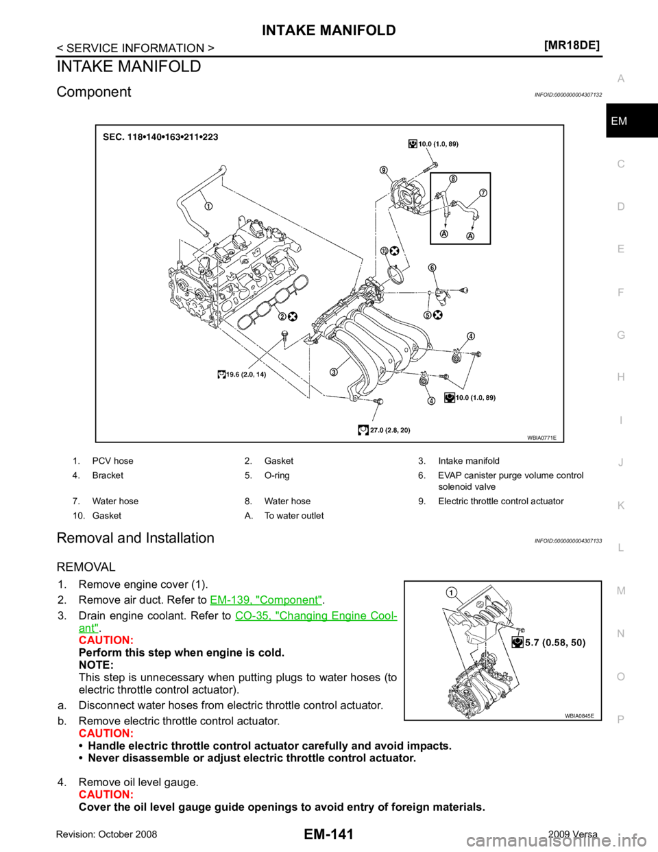
INTAKE MANIFOLD
Component INFOID:0000000004307132
Removal and Installation INFOID:0000000004307133
REMOVAL 1. Remove engine cover (1).
2. Remove air duct. Refer to EM-139, " Component " .
3. Drain engine coolant. Refer to CO-35, " Changing Engine Cool-
ant " .
CAUTION:
Perform this step when engine is cold.
NOTE:
This step is unnecessary when putting plugs to water hoses (to
electric throttle control actuator).
a. Disconnect water hoses from electr ic throttle control actuator.
b. Remove electric throttle control actuator. CAUTION:
• Handle electric throttle control act uator carefully and avoid impacts.
• Never disassemble or adjust elect ric throttle control actuator.
4. Remove oil level gauge. CAUTION:
Cover the oil level gauge guide openings to avoid entry of foreign materials.
1. PCV hose 2. Gasket 3. Intake manifold
4. Bracket 5. O-ring 6. EVAP canister purge volume control solenoid valve
7. Water hose 8. Water hose 9. Electric throttle control actuator
10. Gasket A. To water outlet WBIA0845E