Page 1397 of 4331

EC
NP
O
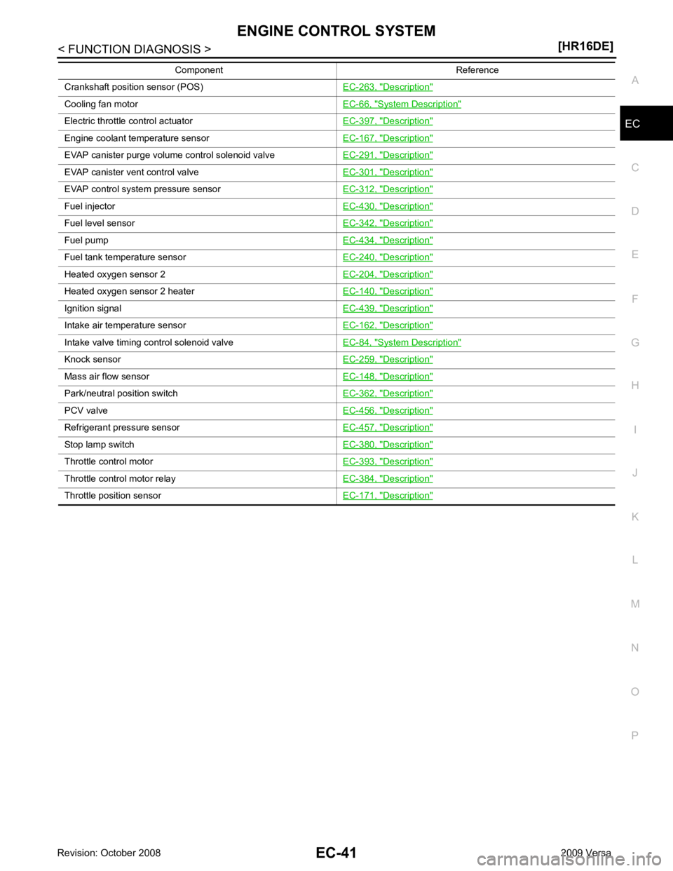
Crankshaft position sensor (POS)
EC-263, " Description "
Cooling fan motor
EC-66, " System Description "
Electric throttle control actuator
EC-397, " Description "
Engine coolant temperature sensor
EC-167, " Description "
EVAP canister purge volume control solenoid valve
EC-291, " Description "
EVAP canister vent control valve
EC-301, " Description "
EVAP control system pressure sensor
EC-312, " Description "
Fuel injector
EC-430, " Description "
Fuel level sensor
EC-342, " Description "
Fuel pump
EC-434, " Description "
Fuel tank temperature sensor
EC-240, " Description "
Heated oxygen sensor 2
EC-204, " Description "
Heated oxygen sensor 2 heater
EC-140, " Description "
Ignition signal
EC-439, " Description "
Intake air temperature sensor
EC-162, " Description "
Intake valve timing control solenoid valve
EC-84, " System Description "
Knock sensor
EC-259, " Description "
Mass air flow sensor
EC-148, " Description "
Park/neutral position switch
EC-362, " Description "
PCV valve
EC-456, " Description "
Refrigerant pressure sensor
EC-457, " Description "
Stop lamp switch
EC-380, " Description "
Throttle control motor
EC-393, " Description "
Throttle control motor relay
EC-384, " Description "
Throttle position sensor
EC-171, " Description "Component Reference
Page 1412 of 4331
EC-56< FUNCTION DIAGNOSIS >
[HR16DE]
ELECTRIC IGNITION SYSTEM
Component Description INFOID:0000000004780017
1. Cooling fan motor harness connec-
tor 2. Crankshaft position sensor 3. Stop lamp switch
4. Brake pedal 5. Accelerator pedal position sensor harness connector6. Accelerator pedal position sensor
7. Accelerator pedal 8. Fuel level sensor unit and fuel pump harness connector (view with in-
spection hole cover removed) 9. Fuel pressure regulator
10. Fuel pump AWBIA0044ZZ
Component Reference
Accelerator pedal position sensor EC-399, " Description "
Camshaft position sensor (PHASE)
EC-268, " Description "
Crankshaft position sensor (POS)
EC-263, " Description "
Engine coolant temperature sensor
EC-167, " Description "
Page 1445 of 4331
INTAKE VALVE TIMING CONTROL
EC-89
< FUNCTION DIAGNOSIS >
[HR16DE] C
D E
F
G H
I
J
K L
M A EC
NP
O
Component Description INFOID:0000000004780038
1. Cooling fan motor harness connec-
tor 2. Crankshaft position sensor 3. Stop lamp switch
4. Brake pedal 5. Accelerator pedal position sensor harness connector6. Accelerator pedal position sensor
7. Accelerator pedal 8. Fuel level sensor unit and fuel pump harness connector (view with in-
spection hole cover removed) 9. Fuel pressure regulator
10. Fuel pump AWBIA0044ZZ
Component Reference
Camshaft position sensor (PHASE) EC-268, " Description "
Crankshaft position sensor (POS)
EC-263, " Description "
Engine coolant temperature sensor
EC-167, " Description "
Intake valve timing control solenoid valve
EC-84, " System Description "
Page 1521 of 4331
![NISSAN LATIO 2009 Service Repair Manual P0116 ECT SENSOR
EC-165
< COMPONENT DIAGNOSIS >
[HR16DE] C
D E
F
G H
I
J
K L
M A EC
NP
O
P0116 ECT SENSOR
Description INFOID:0000000004780447
The engine coolant temperature sensor is used to detect th NISSAN LATIO 2009 Service Repair Manual P0116 ECT SENSOR
EC-165
< COMPONENT DIAGNOSIS >
[HR16DE] C
D E
F
G H
I
J
K L
M A EC
NP
O
P0116 ECT SENSOR
Description INFOID:0000000004780447
The engine coolant temperature sensor is used to detect th](/manual-img/5/57359/w960_57359-1520.png)
P0116 ECT SENSOR
EC-165
< COMPONENT DIAGNOSIS >
[HR16DE] C
D E
F
G H
I
J
K L
M A EC
NP
O
P0116 ECT SENSOR
Description INFOID:0000000004780447
The engine coolant temperature sensor is used to detect the engine
coolant temperature. The sensor modifies a voltage signal from the
ECM. The modified signal returns to the ECM as the engine coolant
temperature input. The sensor uses a thermistor which is sensitive to
the change in temperature. The electrical resistance of the ther-
mistor decreases as temperature increases.
*: These data are reference values and are measured between ECM terminal 38
(Engine coolant temperature sensor) and ground.
CAUTION:
Do not use ECM ground terminals when measuring input/output vo ltage. Doing so may result in damage to the ECM's transis-
tor. Use a ground other than ECM terminals, such as the ground.
DTC Logic INFOID:0000000004780084
DTC DETECTION LOGIC NOTE:
If DTC P0116 is displayed with P0117 or P0118, first perform the trouble diagnosis for DTC P0117,
P0118. Refer to EC-167, " DTC Logic " .
DTC CONFIRMATION PROCEDURE 1.
PRECONDITIONING
If DTC confirmation procedure has been previously conduc ted, always turn ignition switch OFF and wait at
least 10 seconds before conducting the next test.
>> GO TO 2. 2.
PERFORM DTC CONFIRMATION PROCEDURE
1. Start engine and warm it up to normal operating temperature.
2. Rev engine up to 2,000 rpm for more than 10 minutes.
3. Move the vehicle to a cool place, then stop engine and turn ignition switch OFF.
4. Check resistance between “fuel level s ensor unit and fuel pump” terminals 4 and 5. SEF594K
Engine coolant temperature
[° C ( °F)] Voltage* (V) Resistance (k
Ω)
–10 (14) 4.4 7.0 - 11.4 20 (68) 3.5 2.37 - 2.63
50 (122) 2.2 0.68 - 1.00
90 (194) 0.9 0.236 - 0.260 SEF012P
DTC No. Trouble diagnosis name DTC detecting condition Possible cause
P0116 Engine coolant temperature
sensor circuit range/perfor-
mance Engine coolant temperature signal from engine
coolant temperature sensor does not fluctuate,
even when some time has passed after starting
the engine with pre-warming up condition. • Harness or connectors
(High or low resistance in the circuit)
• Engine coolant temperature sensor
Page 1724 of 4331

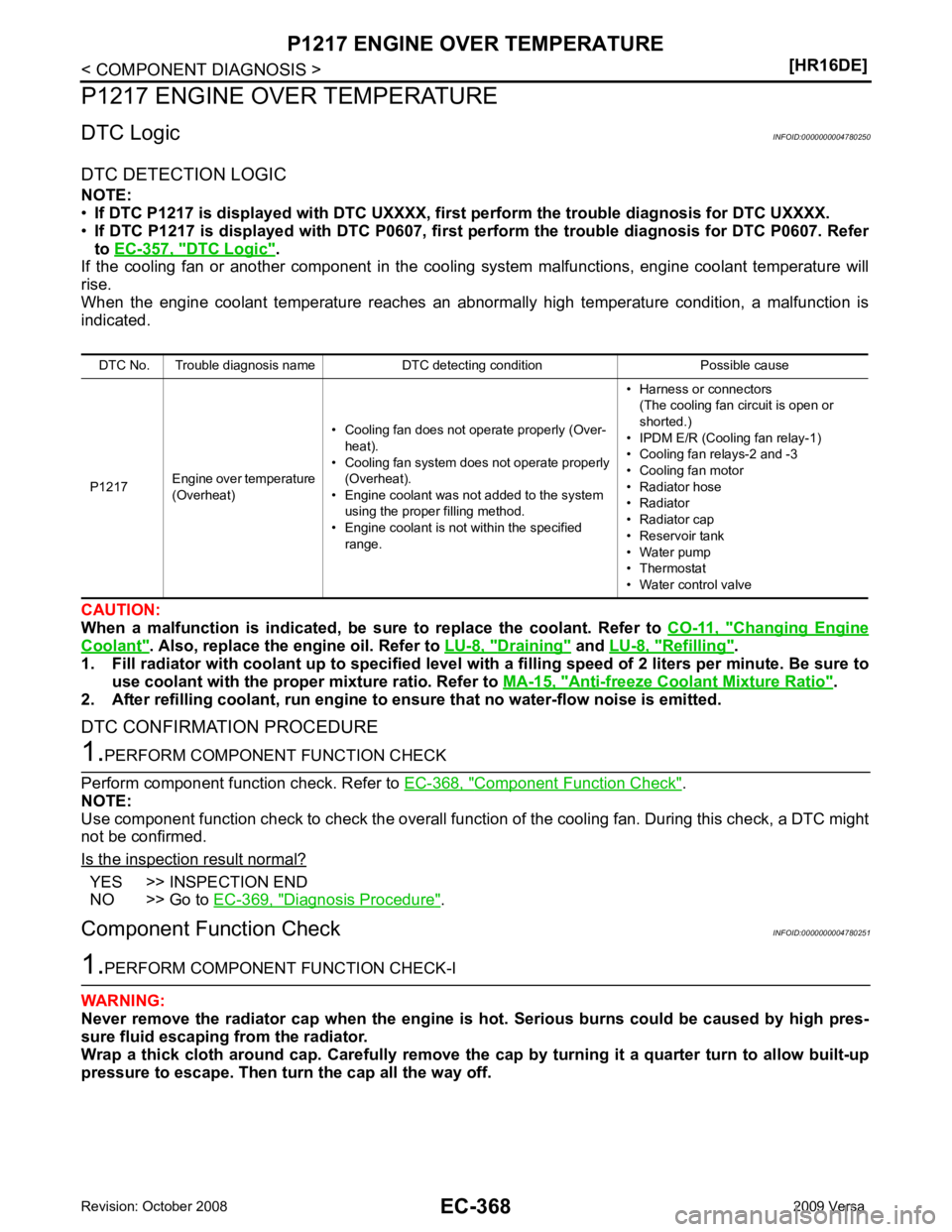
DTC Logic " .
If the cooling fan or another component in the coo ling system malfunctions, engine coolant temperature will
rise.
When the engine coolant temperature reaches an abnorma lly high temperature condition, a malfunction is
indicated.
CAUTION:
When a malfunction is indicated, be su re to replace the coolant. Refer to CO-11, " Changing Engine
Coolant " . Also, replace the engine oil. Refer to
LU-8, " Draining " and
LU-8, " Refilling " .
1. Fill radiator with coolant up to specified level with a filling speed of 2 liters per minute. Be sure to
use coolant with the proper mixture ratio. Refer to MA-15, " Anti-freeze Coolant Mixture Ratio " .
2. After refilling coolant, run engine to en sure that no water-flow noise is emitted.
DTC CONFIRMATION PROCEDURE Component Function Check " .
NOTE:
Use component function check to check the overall functi on of the cooling fan. During this check, a DTC might
not be confirmed.
Is the inspection result normal? YES >> INSPECTION END
NO >> Go to EC-369, " Diagnosis Procedure " .
Component Function Check INFOID:0000000004780251
Page 1725 of 4331
EC
NP
O
Check the coolant level in the reservoir tank and radiator.
Allow engine to cool befo re checking coolant level.
Is the coolant level in the reservoir tank and/or radiator below the proper range?
YES >> Go to
EC-369, " Diagnosis Procedure " .
NO >> GO TO 2. YES >> Go to
EC-369, " Diagnosis Procedure " .
NO >> GO TO 3. Auto Active Test " .
Is the inspection result normal? YES >> INSPECTION END
NO >> Go to EC-369, " Diagnosis Procedure " .
Diagnosis Procedure INFOID:0000000004780252 Auto Active
Test " .
2. Make sure that cooling fan motor operates at each speed (Low/High).
Is the inspection result normal? YES >> GO TO 2.
NO >> Go to EC-424, " Diagnosis Procedure " .
Inspection " .
Is leakage detected? YES >> GO TO 3.
NO >> GO TO 4. Inspection " .)
• Radiator (Refer to CO-14, " Checking Radiator " .)
• Water pump (Refer to CO-21, " Inspection " .)
>> Repair or replace malfunctioning part.
Page 1726 of 4331

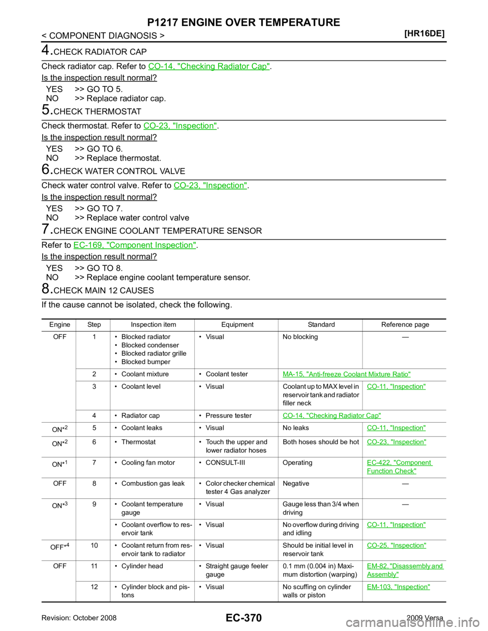
Checking Radiator Cap " .
Is the inspection result normal? YES >> GO TO 5.
NO >> Replace radiator cap. Inspection " .
Is the inspection result normal? YES >> GO TO 6.
NO >> Replace thermostat. Inspection " .
Is the inspection result normal? YES >> GO TO 7.
NO >> Replace water control valve Component Inspection " .
Is the inspection result normal? YES >> GO TO 8.
NO >> Replace engine coolant temperature sensor. Anti-freeze Coolant Mixture Ratio "
3 • Coolant level • Visual Coolant up to MAX level in
reservoir tank and radiator
filler neck CO-11, " Inspection "
4 • Radiator cap • Pressure tester
CO-14, " Checking Radiator Cap "
ON*
2
5 • Coolant leaks • Visual No leaks CO-11, " Inspection "
ON*
2
6 • Thermostat • Touch the upper and
lower radiator hosesBoth hoses should be hot
CO-23, " Inspection "
ON*
1
7 • Cooling fan motor • CONSULT-III Operating EC-422, " Component
Function Check "
OFF 8 • Combustion gas leak • Color checker chemical
tester 4 Gas analyzerNegative —
ON* 3
9 • Coolant temperature
gauge • Visual Gauge less than 3/4 when
driving —
• Coolant overflow to res- ervoir tank • Visual No overflow during driving
and idling CO-11, " Inspection "
OFF*
4
10 • Coolant return from res-
ervoir tank to radiator • Visual Should be initial level in
reservoir tank CO-25, " Inspection "
OFF 11 • Cylinder head • Straight gauge feeler
gauge0.1 mm (0.004 in) Maxi-
mum distortion (warping) EM-82, " Disassembly and
Assembly "
12 • Cylinder block and pis-
tons • Visual No scuffing on cylinder
walls or piston EM-103, " Inspection "
Page 1830 of 4331
Priority Detected items (DTC)
1 • U0101 U0140 U1001 CAN communication line • P0101 P0102 P0103 Mass air flow sensor
• P0112 P0113 P0127 Intake air temperature sensor
• P0116 P0117 P0118 P0125 Engine coolant temperature sensor
• P0122 P0123 P0222 P0223 P1225 P1226 P2135 Throttle position sensor
• P0128 Thermostat function
• P0181 P0182 P0183 Fuel tank temperature sensor
• P0327 P0328 Knock sensor
• P0335 Crankshaft position sensor (POS)
• P0340 Camshaft posi tion sensor (PHASE)
• P0460 P0461 P0462 P0463 Fuel level sensor
• P0500 Vehicle speed sensor
• P0605 P0607 ECM
• P0643 Sensor power supply
• P0705 P0850 Park/neutral position (PNP) switch
• P1610 - P1615 NATS
• P2122 P2123 P2127 P2128 P2138 Accelerator pedal position sensor