2009 NISSAN LATIO engine coolant
[x] Cancel search: engine coolantPage 2765 of 4331
EC
NP
O
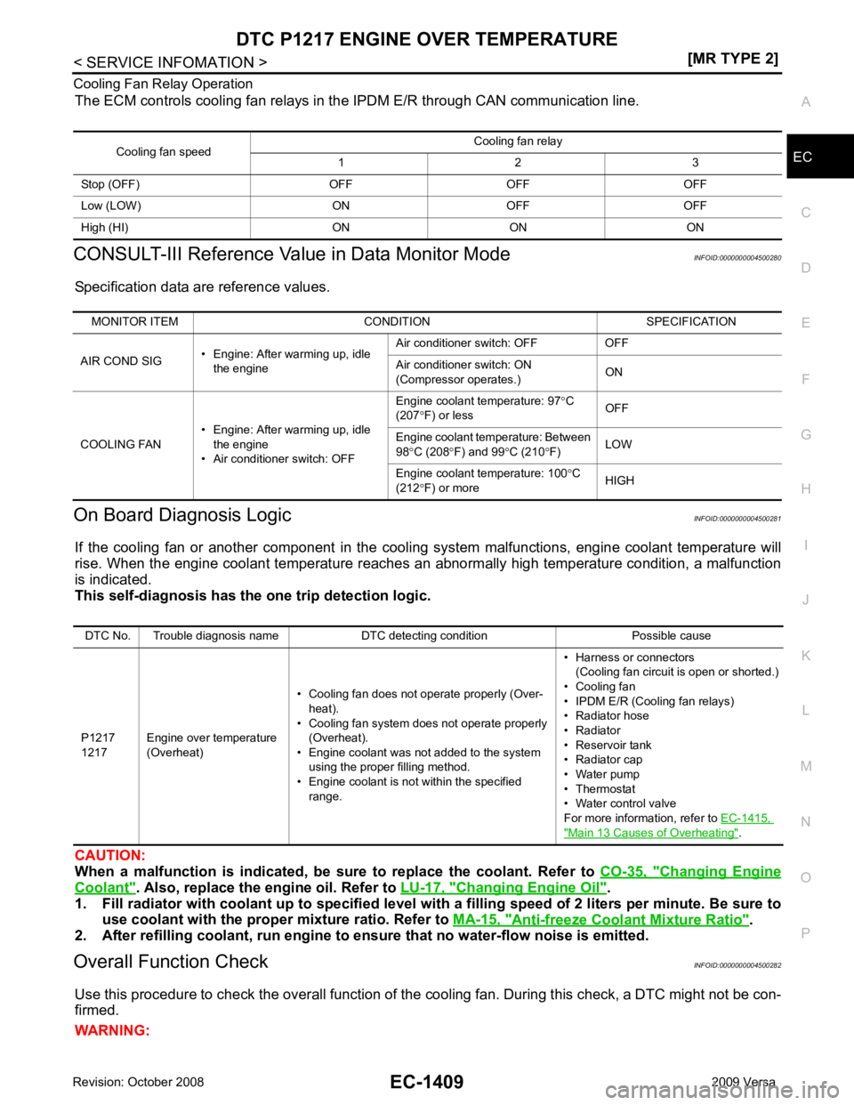
Cooling Fan Relay Operation
The ECM controls cooling fan relays in the IPDM E/R through CAN communication line.
CONSULT-III Reference Val ue in Data Monitor Mode INFOID:0000000004500280
Specification data are reference values.
On Board Diagnosis Logic INFOID:0000000004500281
If the cooling fan or another component in the cooli ng system malfunctions, engine coolant temperature will
rise. When the engine coolant temperature reaches an abnormally high temperature condition, a malfunction
is indicated.
This self-diagnosis has the on e trip detection logic.
CAUTION:
When a malfunction is in dicated, be sure to replace the coolant. Refer to CO-35, " Changing Engine
Coolant " . Also, replace the engine oil. Refer to
LU-17, " Changing Engine Oil " .
1. Fill radiator with coolant up to specified level with a filling speed of 2 liters per minute. Be sure to
use coolant with the proper mixture ratio. Refer to MA-15, " Anti-freeze Coolant Mixture Ratio " .
2. After refilling coolant, run engine to ensure that no water-flow noise is emitted.
Overall Function Check INFOID:0000000004500282
Use this procedure to check the overall function of the cooling fan. During this check, a DTC might not be con-
firmed.
WARNING: Cooling fan speed
Cooling fan relay
1 2 3
Stop (OFF) OFF OFF OFF
Low (LOW) ON OFF OFF
High (HI) ON ON ON MONITOR ITEM CONDITION SPECIFICATION
AIR COND SIG • Engine: After warming up, idle
the engine Air conditioner switch: OFF OFF
Air conditioner switch: ON
(Compressor operates.) ON
COOLING FAN • Engine: After warming up, idle
the engine
• Air conditioner switch: OFF Engine coolant temperature: 97
°C
(207 °F) or less OFF
Engine coolant temperature: Between
98 °C (208 °F) and 99 °C (210 °F) LOW
Engine coolant temperature: 100 °C
(212 °F) or more HIGHDTC No. Trouble diagnosis name DTC detecting condition Possible cause
P1217
1217 Engine over temperature
(Overheat) • Cooling fan does not operate properly (Over-
heat).
• Cooling fan system does not operate properly (Overheat).
• Engine coolant was not added to the system using the proper filling method.
• Engine coolant is not within the specified
range. • Harness or connectors
(Cooling fan circuit is open or shorted.)
• Cooling fan
• IPDM E/R (Cooling fan relays)
• Radiator hose
• Radiator
• Reservoir tank
• Radiator cap
• Water pump
• Thermostat
• Water control valve
For more information, refer to EC-1415, " Main 13 Causes of Overheating " .
Page 2766 of 4331
![NISSAN LATIO 2009 Service Repair Manual EC-1410< SERVICE INFOMATION >
[MR TYPE 2]
DTC P1217 ENGINE
OVER TEMPERATURE
Never remove the radiator cap when the engine is hot. Serious burns could be caused by high pres-
sure flu NISSAN LATIO 2009 Service Repair Manual EC-1410< SERVICE INFOMATION >
[MR TYPE 2]
DTC P1217 ENGINE
OVER TEMPERATURE
Never remove the radiator cap when the engine is hot. Serious burns could be caused by high pres-
sure flu](/manual-img/5/57359/w960_57359-2765.png)
EC-1410< SERVICE INFOMATION >
[MR TYPE 2]
DTC P1217 ENGINE
OVER TEMPERATURE
Never remove the radiator cap when the engine is hot. Serious burns could be caused by high pres-
sure fluid escaping from the reser voir tank or the radiator.
Wrap a thick cloth around cap. Carefully remove the cap by turning it a quarter turn to allow built-up
pressure to escape. Then turn the cap all the way off.
WITH CONSULT-III
1. Check the coolant level in the reservoir tank and radiator. Allow engine to cool before checking coolant level.
If the coolant level in the reservoir tank and/or radiator is below
the proper range, skip the following steps and go to EC-1412," Diagnosis Procedure " or
EC-1412, " Diagnosis Procedure " .
2. Confirm whether customer filled the coolant or not. If customer
filled the coolant, skip the following steps and go to EC-1412," Diagnosis Procedure " or
EC-1412, " Diagnosis Procedure " .
3. Turn ignition switch ON.
4. Perform “COOLING FAN” in “ACTIVE TEST” mode with CON- SULT-III.
5. If the results are NG, go to EC-1412, " Diagnosis Procedure " or
EC-1412, " Diagnosis Procedure " .
WITH GST
1. Check the coolant level in the reservoir tank and radiator. Allow engine to cool before checking coolant level.
If the coolant level in the reservoir tank and/or radiator is below
the proper range, skip the following steps and go to EC-1412," Diagnosis Procedure " .
2. Confirm whether customer filled the coolant or not. If customer
filled the coolant, skip the following steps and go to EC-1412," Diagnosis Procedure " .
3. Perform IPDM/ER auto active te st and check cooling fan motor
operation. Refer to PG-19, " Auto Active Test " .
4. If NG, go to EC-1412, " Diagnosis Procedure " . SEF621W
SEF621W
Page 2769 of 4331
EC
NP
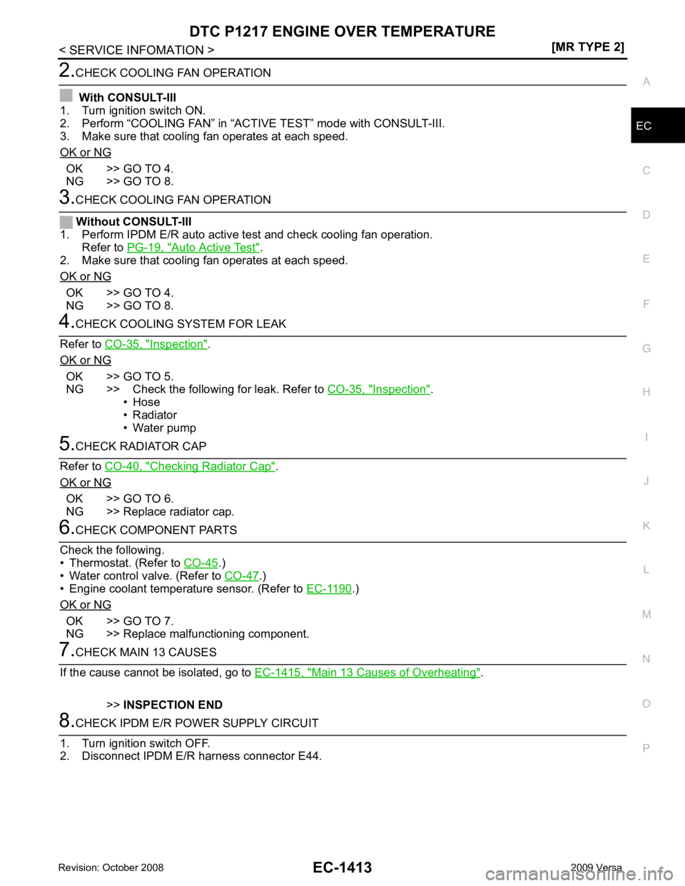
O OK >> GO TO 4.
NG >> GO TO 8. Auto Active Test " .
2. Make sure that cooling fan operates at each speed.
OK or NG OK >> GO TO 4.
NG >> GO TO 8. Inspection " .
OK or NG OK >> GO TO 5.
NG >> Check the following for leak. Refer to CO-35, " Inspection " .
• Hose
• Radiator
• Water pump Checking Radiator Cap " .
OK or NG OK >> GO TO 6.
NG >> Replace radiator cap. .)
• Water control valve. (Refer to CO-47 .)
• Engine coolant temperature sensor. (Refer to EC-1190 .)
OK or NG OK >> GO TO 7.
NG >> Replace malfunctioning component. Main 13 Causes of Overheating " .
>> INSPECTION END
Page 2771 of 4331
EC
NP
O
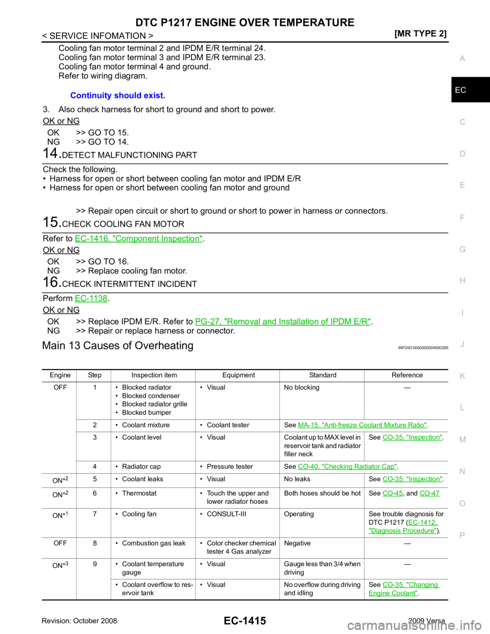
Cooling fan motor terminal 2 and IPDM E/R terminal 24.
Cooling fan motor terminal 3 and IPDM E/R terminal 23.
Cooling fan motor terminal 4 and ground.
Refer to wiring diagram.
3. Also check harness for short to ground and short to power.
OK or NG OK >> GO TO 15.
NG >> GO TO 14. Component Inspection " .
OK or NG OK >> GO TO 16.
NG >> Replace cooling fan motor. .
OK or NG OK >> Replace IPDM E/R. Refer to
PG-27, " Removal and Installation of IPDM E/R " .
NG >> Repair or replace harness or connector.
Main 13 Causes of Overheating INFOID:0000000004500285
Continuity should exist.
Engine Step Inspection item Equipment Standard Reference OFF 1 • Blocked radiator • Blocked condenser
• Blocked radiator grille
• Blocked bumper • Visual No blocking —
2 • Coolant mixture • Coolant tester See MA-15, " Anti-freeze Coolant Mixture Ratio " .
3 • Coolant level • Visual Coolant up to MAX level in reservoir tank and radiator
filler neck See
CO-35, " Inspection " .
4 • Radiator cap • Pressure tester See CO-40, " Checking Radiator Cap " .
ON* 2
5 • Coolant leaks • Visual No leaks See CO-35, " Inspection " .
ON* 2
6 • Thermostat • Touch the upper and
lower radiator hosesBoth hoses should be hot See
CO-45 , and
CO-47 ON*
1
7 • Cooling fan • CONSULT-III Operating See trouble diagnosis for
DTC P1217 (EC-1412, " Diagnosis Procedure " ).
OFF 8 • Combustion gas leak • Color checker chemical tester 4 Gas analyzerNegative —
ON* 3
9 • Coolant temperature
gauge • Visual Gauge less than 3/4 when
driving —
• Coolant overflow to res- ervoir tank • Visual No overflow during driving
and idling See
CO-35, " Changing
Engine Coolant " .
Page 2772 of 4331
![NISSAN LATIO 2009 Service Repair Manual EC-1416< SERVICE INFOMATION >
[MR TYPE 2]
DTC P1217 ENGINE
OVER TEMPERATURE
*1: Turn the ignition switch ON.
*2: Engine running at 3,000 rpm for 10 minutes.
*3: Drive at 90 km/h (55 MPH) for 30 minut NISSAN LATIO 2009 Service Repair Manual EC-1416< SERVICE INFOMATION >
[MR TYPE 2]
DTC P1217 ENGINE
OVER TEMPERATURE
*1: Turn the ignition switch ON.
*2: Engine running at 3,000 rpm for 10 minutes.
*3: Drive at 90 km/h (55 MPH) for 30 minut](/manual-img/5/57359/w960_57359-2771.png)
EC-1416< SERVICE INFOMATION >
[MR TYPE 2]
DTC P1217 ENGINE
OVER TEMPERATURE
*1: Turn the ignition switch ON.
*2: Engine running at 3,000 rpm for 10 minutes.
*3: Drive at 90 km/h (55 MPH) for 30 minutes and then let idle for 10 minutes.
*4: After 60 minutes of cool down time.
For more informat ion, refer to CO-32 .
Component Inspection INFOID:0000000004500286
COOLING FAN MOTOR
Model with A/C
1. Disconnect cooling fan motor harness connectors.
2. Supply cooling fan motor terminals with battery voltage and check operation.
Cooling fan motor should operate.
If NG, replace cooling fan motor.
Models without A/C
1. Disconnect cooling fan motor harness connectors.
2. Supply cooling fan motor terminals with battery voltage and check operation.
Cooling fan motor should operate.
If NG, replace cooling fan motor. OFF*
4
10 • Coolant return from res-
ervoir tank to radiator • Visual Should be initial level in
reservoir tank See
CO-35, " Inspection " .
OFF 11 • Water control valve • Remove and inspect
the valve Within the specified value See
CO-47, " Removal
and Installation "
OFF 12 • Cylinder head • Straight gauge feeler
gauge0.1 mm (0.004 in) Maxi-
mum distortion (warping) See
EM-185 .
13 • Cylinder block and pis- tons • Visual No scuffing on cylinder
walls or piston See
EM-199 .
Engine Step Inspection item Equipment Standard Reference Terminals
(+) (-)
Cooling fan motor 1 2 SEF888V
Speed
terminals
(+) ( −)
Cooling fan motor Low 1 4
2 3
High 1 and 2 3 and 4 SEF734W
Page 2952 of 4331
![NISSAN LATIO 2009 Service Repair Manual PRECAUTIONS
EM-5
< PRECAUTION >
[HR16DE] C
D E
F
G H
I
J
K L
M A EM
NP
O
5. When the repair work is completed, return the ignition switch to the
″LOCK ″ position before connecting
t NISSAN LATIO 2009 Service Repair Manual PRECAUTIONS
EM-5
< PRECAUTION >
[HR16DE] C
D E
F
G H
I
J
K L
M A EM
NP
O
5. When the repair work is completed, return the ignition switch to the
″LOCK ″ position before connecting
t](/manual-img/5/57359/w960_57359-2951.png)
PRECAUTIONS
EM-5
< PRECAUTION >
[HR16DE] C
D E
F
G H
I
J
K L
M A EM
NP
O
5. When the repair work is completed, return the ignition switch to the
″LOCK ″ position before connecting
the battery cables. (At this time, the steering lock mechanism will engage.)
6. Perform a self-diagnosis check of al l control units using CONSULT-III.
Precaution for Procedur e without Cowl Top Cover INFOID:0000000004784258
When performing the procedure after removing cowl top cover, cover
the lower end of windshield.
Precaution for Drain Coolant INFOID:0000000004784260
• Drain coolant when engine is cooled.
Precaution for Disco nnecting Fuel Piping INFOID:0000000004784261
• Before starting work, make sure no fire or spark producing items are in the work area.
• Release fuel pressure before disassembly.
• After disconnecting pipes, plug openings to stop fuel leakage.
Precaution for Removal and Disassembly INFOID:0000000004784262
• When instructed to use special service tools, use the spec ified tools. Always be careful to work safely, avoid
forceful or uninstructed operations.
• Exercise maximum care to avoid damage to mating or sliding surfaces.
• Cover openings of engine system with tape or the equiva lent, if necessary, to seal out foreign materials.
• Mark and arrange disassembly parts in an organized way for easy troubleshooting and assembly.
• When loosening nuts and bolts, as a basic rule, start with the one furthest outside, then the one diagonally opposite, and so on. If the order of loosening is specif ied, do exactly as specified. Power tools may be used
where noted in the step.
Precaution for Inspection, Repair and Replacement INFOID:0000000004784263
• Before repairing or replacing, thoroughly inspect parts. Inspect new replacement parts in the same way, and
replace if necessary.
Precaution for Assembly and Installation INFOID:0000000004784264
• Use torque wrench to tighten bolts or nuts to specification.
• When tightening nuts and bolts, as a basic rule, equally tighten in several different steps starting with the ones in center, then ones on inside and outside diagonally in this order. If the order of tightening is specified,
do exactly as specified.
• Replace with new gasket, packing, oil seal or O-ring.
• Thoroughly wash, clean, and air-blow each part. Carefully check oil or coolant passages for any restriction
and blockage.
• Avoid damaging sliding or mating surfaces. Completely remove foreign materials such as cloth lint or dust. Before assembly, oil sliding surfaces well.
• Release air within route after draining coolant.
• Before starting engine, apply fuel pressure to fuel lines with turning ignition switch ON (with engine stopped). Then make sure that there are no leaks at fuel line connections.
• After repairing, start engine and increase engine speed to check coolant, fuel, oil, and exhaust systems for leakage. PIIB3706J
Page 2954 of 4331
EM
NP
O
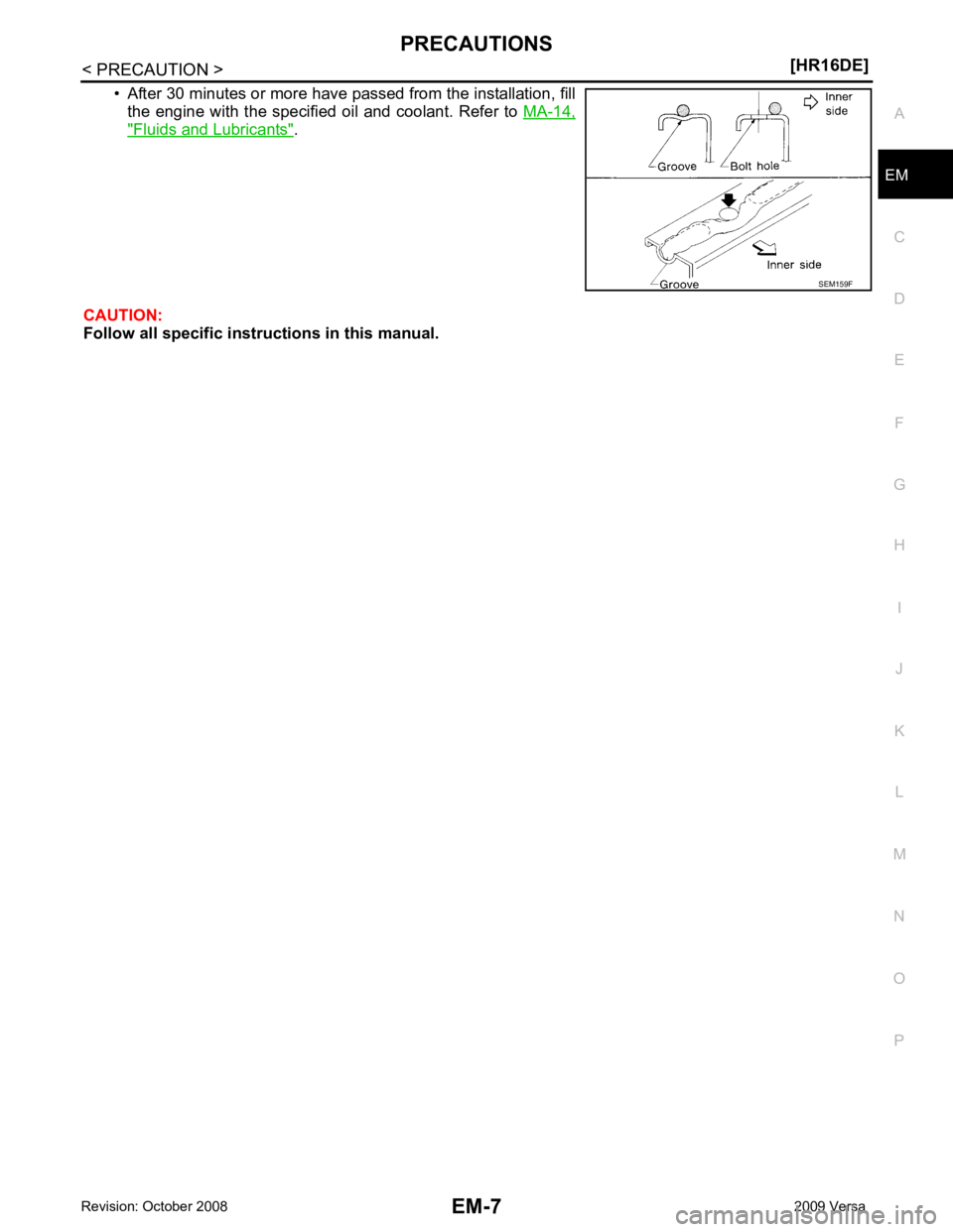
• After 30 minutes or more have passed from the installation, fill
the engine with the specified oil and coolant. Refer to MA-14," Fluids and Lubricants " .
CAUTION:
Follow all specific instruct ions in this manual.
Page 3004 of 4331
EM
NP
O
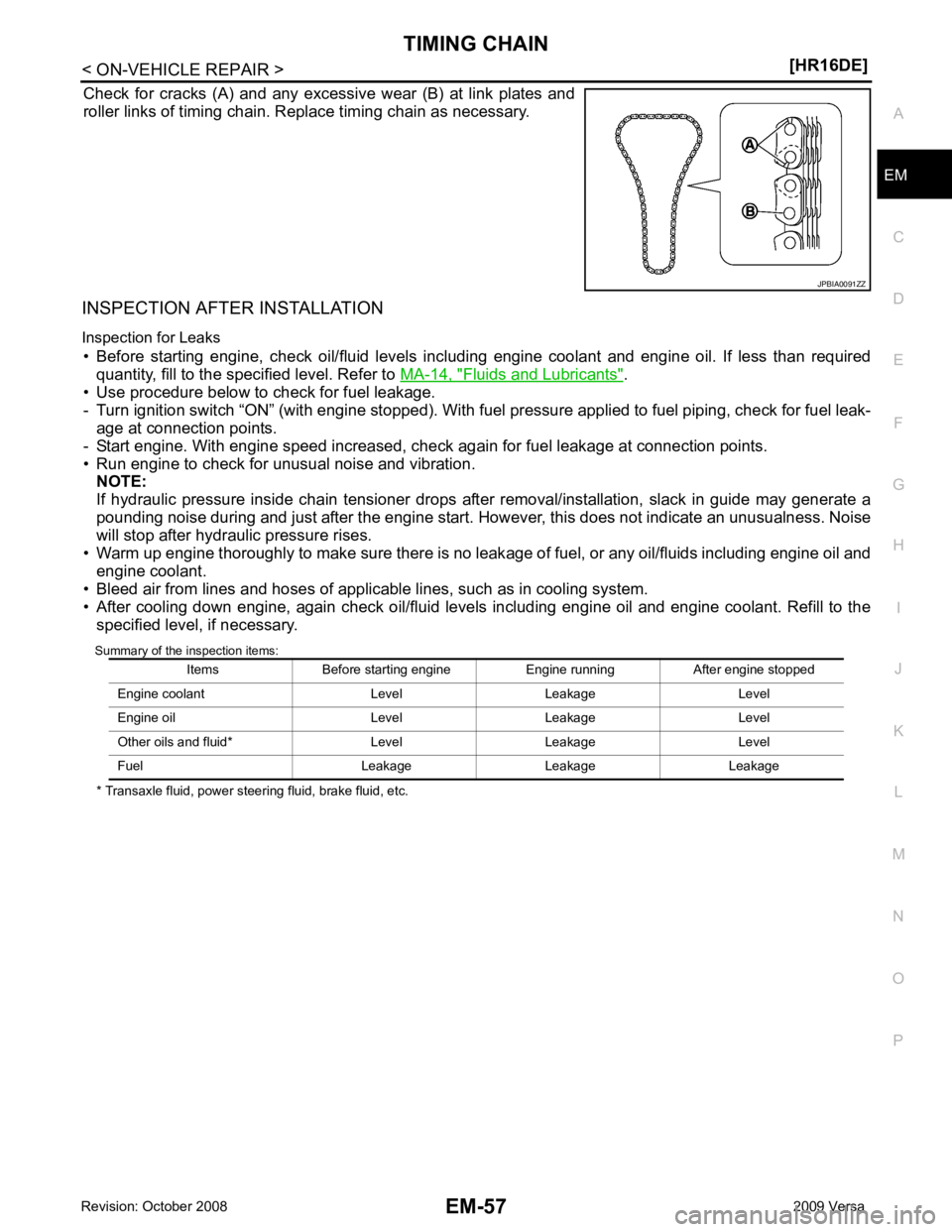
Check for cracks (A) and any excessive wear (B) at link plates and
roller links of timing chain. Replace timing chain as necessary.
INSPECTION AFTER INSTALLATION
Inspection for Leaks • Before starting engine, check oil/fluid levels incl uding engine coolant and engine oil. If less than required
quantity, fill to the specified level. Refer to MA-14, " Fluids and Lubricants " .
• Use procedure below to check for fuel leakage.
- Turn ignition switch “ON” (with engine stopped). With fuel pressure applied to fuel piping, check for fuel leak-
age at connection points.
- Start engine. With engine speed increased, check again for fuel leakage at connection points.
• Run engine to check for unusual noise and vibration. NOTE:
If hydraulic pressure inside chain tensioner drops after removal/installation, slack in guide may generate a
pounding noise during and just after the engine start. However, this does not indicate an unusualness. Noise
will stop after hydraulic pressure rises.
• Warm up engine thoroughly to make sure there is no leak age of fuel, or any oil/fluids including engine oil and
engine coolant.
• Bleed air from lines and hoses of applicable lines, such as in cooling system.
• After cooling down engine, again check oil/fluid levels including engine oil and engine coolant. Refill to the specified level, if necessary.
Summary of the inspection items:
* Transaxle fluid, power steering fluid, brake fluid, etc.