2009 NISSAN LATIO service
[x] Cancel search: servicePage 3341 of 4331
GW-38< SERVICE INFORMATION >
POWER WINDOW SYSTEM
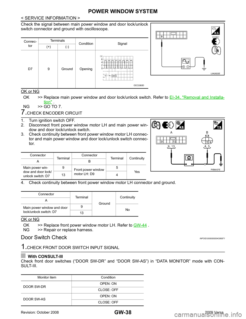
Check the signal between main power window and door lock/unlock
switch connector and ground with oscilloscope.
OK or NG OK >> Replace main power window and door lock/unlock switch. Refer to
EI-34, " Removal and Installa-
tion " .
NG >> GO TO 7. 7.
CHECK ENCODER CIRCUIT
1. Turn ignition switch OFF.
2. Disconnect front power window motor LH and main power win-
dow and door lock/unlock switch.
3. Check continuity between front power window motor LH connec-
tor and main power window and door lock/unlock switch connec-
tor.
4. Check continuity between front power window motor LH connector and ground.
OK or NG OK >> Replace front power window motor LH. Refer to
GW-44 .
NG >> Repair or replace harness.
Door Switch Check INFOID:00000000043068711.
CHECK FRONT DOOR SWITCH INPUT SIGNAL
With CONSULT-III
Check front door switches (“DOOR SW-DR” and “D OOR SW-AS”) in “DATA MONITOR” mode with CON-
SULT-III. Connec-
tor Terminals
Condition Signal
(+) (-)
D7 9 Ground Opening LIIA2633E
OCC3383D
Connector TerminalConnector
Terminal Continuity
A B
Main power win-
dow and door lock/
unlock switch: D7 9
Front power window
motor LH: D9 5
Yes
13 4
Connector Terminal
GroundContinuity
A
Main power window and door
lock/unlock switch: D7 9
No
13 PIIB6437E
Monitor item Condition
DOOR SW-DR OPEN: ON
CLOSE: OFF
DOOR SW-AS OPEN: ON
CLOSE: OFF
Page 3345 of 4331
GW-42< SERVICE INFORMATION >
POWER WINDOW SYSTEM
NG >> Repair or replace harness.
Rear Power Window Moto r RH Circuit Inspection INFOID:00000000043068751.
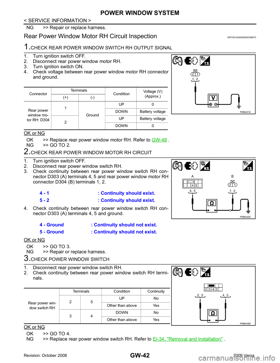
CHECK REAR POWER WINDOW SWITCH RH OUTPUT SIGNAL
1. Turn ignition switch OFF.
2. Disconnect rear power window motor RH.
3. Turn ignition switch ON.
4. Check voltage between rear power window motor RH connector
and ground.
OK or NG OK >> Replace rear power window motor RH. Refer to
GW-48 .
NG >> GO TO 2. 2.
CHECK REAR POWER WINDOW MOTOR RH CIRCUIT
1. Turn ignition switch OFF.
2. Disconnect rear power window switch RH.
3. Check continuity between rear power window switch RH con- nector D303 (A) terminals 4, 5 and rear power window motor RH
connector D304 (B) terminals 1, 2.
4. Check continuity between rear power window switch RH con- nector D303 (A) terminals 4, 5 and ground.
OK or NG OK >> GO TO 3.
NG >> Repair or replace harness. 3.
CHECK POWER WINDOW SWITCH
1. Disconnect rear power window switch RH.
2. Check continuity between rear power window switch RH termi-
nals.
OK or NG OK >> GO TO 4.
NG >> Replace rear power window switch RH. Refer to EI-34, " Removal and Installation " .
Connector
Terminals
ConditionVoltage (V)
(Approx.)
(+) (-)
Rear power
window mo-
tor RH: D304 1
Ground UP 0
DOWN Battery voltage
2 UP Battery voltage
DOWN 0 PIIB6431E
4 - 1 : Continuity should exist.
5 - 2 : Continuity should exist.
4 - Ground : Continuity should not exist.
5 - Ground : Continuity should not exist. PIIB6432E
Rear power win-
dow switch RH Terminals Condition Continuity
2 5 UP No
Other than above Yes
3 4 DOWN No
Other than above Yes PIIB6448E
Page 3371 of 4331

IP
N
O P
CONTENTS
INSTRUMENT PANEL
PRECAUTION ....... ........................................2
PRECAUTIONS .............................................. .....2
Precaution for Supplemental Restraint System
(SRS) "AIR BAG" and "SEAT BELT PRE-TEN-
SIONER" ............................................................. ......
2
Precaution Necessary fo r Steering Wheel Rota-
tion After Battery Disconnect ............................... ......
2
Precaution ........................................................... ......2
PREPARATION .... ........................................4
PREPARATION .............................................. .....4
Special Service Tool ........................................... ......4
Commercial Service Tool .................................... ......4 SYMPTOM DIAGNOSIS ....
...........................5
SQUEAK AND RATTLE TROUBLE DIAG-
NOSES ............................................................... 5
Work Flow ............................................................ .....5
Generic Squeak and Rattle Troubleshooting ....... .....7
Diagnostic Worksheet .......................................... .....9
ON-VEHICLE REPAIR ..... ............................11
INSTRUMENT PANEL ASSEMBLY ................. 11
Component Parts ................................................. ....11
Removal and Installation ..................................... ....12
Disassembly and Assembly ................................. ....23
Page 3374 of 4331
IP-4< PREPARATION >
PREPARATION
PREPARATION
PREPARATION
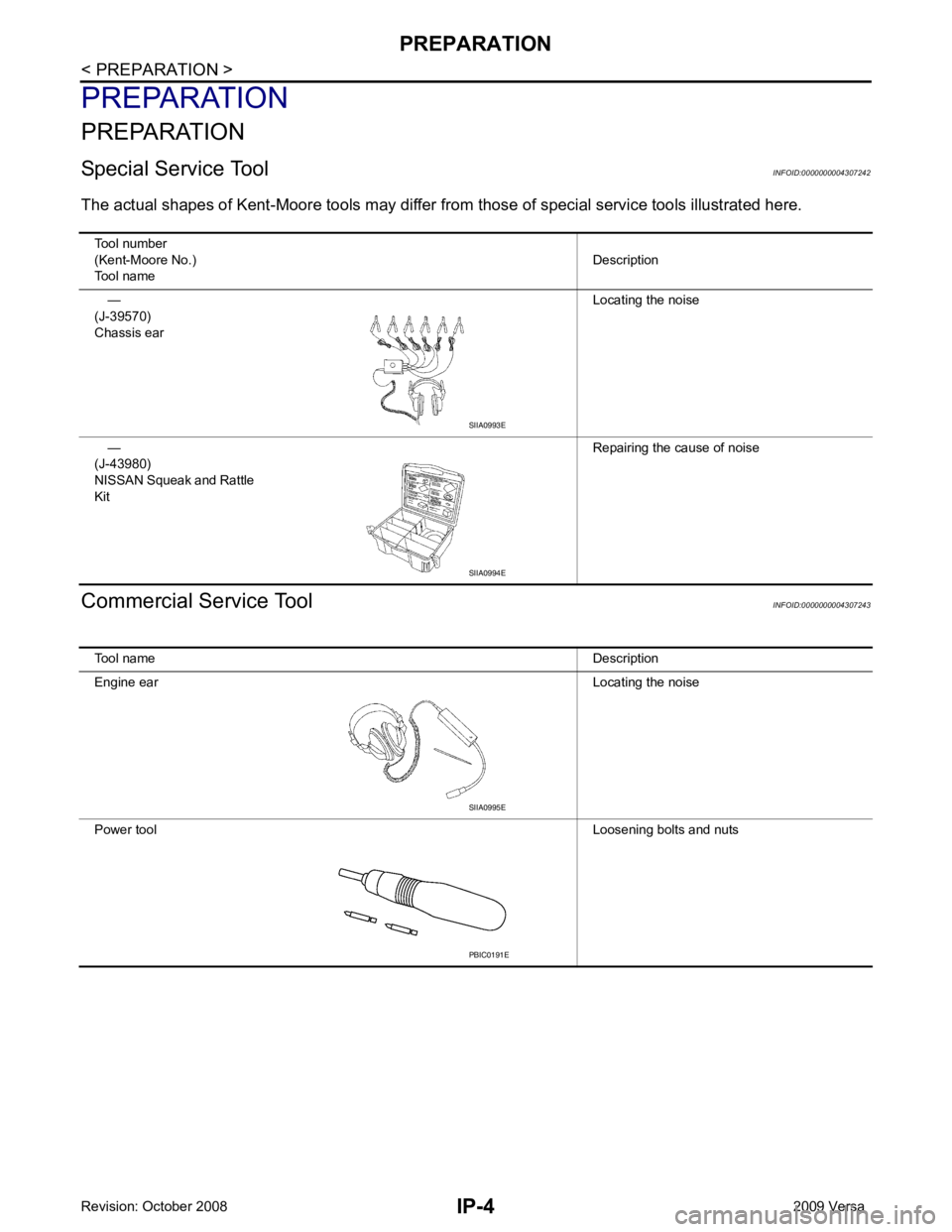
Special Service Tool INFOID:0000000004307242
The actual shapes of Kent -Moore tools may differ from those of special service tools illustrated here.
Commercial Service Tool INFOID:0000000004307243
Tool number
(Kent-Moore No.)
Tool name Description
—
(J-39570)
Chassis ear Locating the noise
—
(J-43980)
NISSAN Squeak and Rattle
Kit Repairing the cause of noiseSIIA0993E
SIIA0994E
Tool name Description
Engine ear Locating the noise
Power tool Loosening bolts and nutsSIIA0995E
PBIC0191E
Page 3375 of 4331
SQUEAK AND RATTLE TROUBLE DIAGNOSES
IP-5
< SYMPTOM DIAGNOSIS >
C
D E
F
G H
J
K L
M A
B IP
N
O P
SYMPTOM DIAGNOSIS
SQUEAK AND RATTLE TROUBLE DIAGNOSES
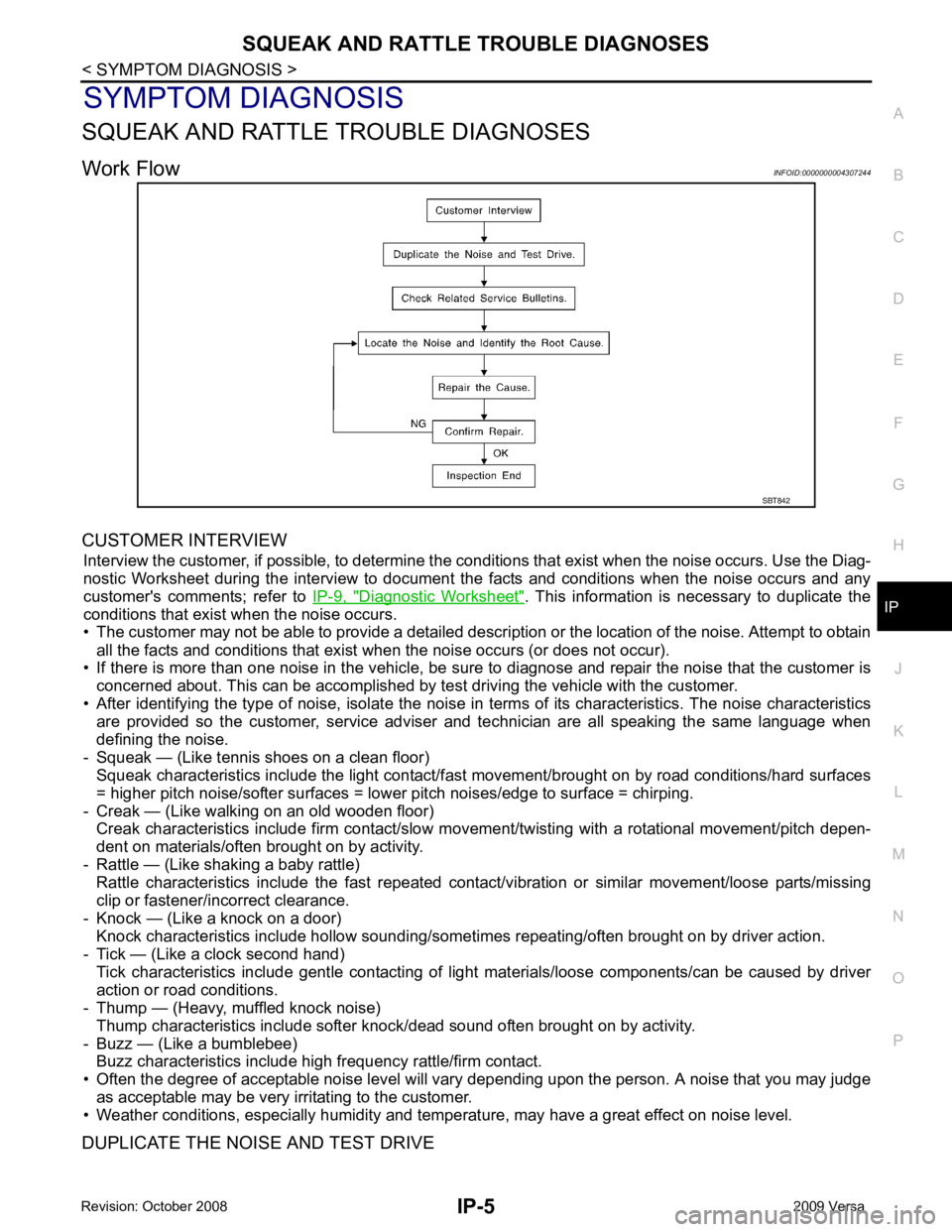
Work Flow INFOID:0000000004307244
CUSTOMER INTERVIEW Interview the customer, if possible, to determine the c onditions that exist when the noise occurs. Use the Diag-
nostic Worksheet during the interv iew to document the facts and conditions when the noise occurs and any
customer's comments; refer to IP-9, " Diagnostic Worksheet " . This information is necessary to duplicate the
conditions that exist when the noise occurs.
• The customer may not be able to provide a detailed descr iption or the location of the noise. Attempt to obtain
all the facts and conditions that exist when the noise occurs (or does not occur).
• If there is more than one noise in the vehicle, be sure to diagnose and repair the noise that the customer is
concerned about. This can be accomplished by te st driving the vehicle with the customer.
• After identifying the type of noise, isolate the noise in terms of its characteristics. The noise characteristics
are provided so the customer, service adviser and technician are all speaking the same language when
defining the noise.
- Squeak — (Like tennis shoes on a clean floor) Squeak characteristics include the light contact/fast movement/brought on by road conditions/hard surfaces
= higher pitch noise/softer surfaces = lower pitch noises/edge to surface = chirping.
- Creak — (Like walking on an old wooden floor) Creak characteristics include firm contact/slow mo vement/twisting with a rotational movement/pitch depen-
dent on materials/often brought on by activity.
- Rattle — (Like shaking a baby rattle) Rattle characteristics include the fast repeated contac t/vibration or similar movement/loose parts/missing
clip or fastener/incorrect clearance.
- Knock — (Like a knock on a door) Knock characteristics include hollow sounding/someti mes repeating/often brought on by driver action.
- Tick — (Like a clock second hand) Tick characteristics include gentle contacting of li ght materials/loose components/can be caused by driver
action or road conditions.
- Thump — (Heavy, muffled knock noise)
Thump characteristics include softer k nock/dead sound often brought on by activity.
- Buzz — (Like a bumblebee) Buzz characteristics include high frequency rattle/firm contact.
• Often the degree of acceptable noise level will vary depending upon the person. A noise that you may judge
as acceptable may be very irritating to the customer.
• Weather conditions, especially humidity and temperature, may have a great effect on noise level.
DUPLICATE THE NOISE AND TEST DRIVE SBT842
Page 3418 of 4331
![NISSAN LATIO 2009 Service Repair Manual PRECAUTIONS
LAN-23
< PRECAUTION >
[CAN] C
D E
F
G H
I
J
L
M A
B LAN
N
O P
PRECAUTION
PRECAUTIONS
Precaution for Supplemental Restraint System (SRS) "AIR BAG" and "SEAT BELT
PRE-TENSIONER" INFOID:000 NISSAN LATIO 2009 Service Repair Manual PRECAUTIONS
LAN-23
< PRECAUTION >
[CAN] C
D E
F
G H
I
J
L
M A
B LAN
N
O P
PRECAUTION
PRECAUTIONS
Precaution for Supplemental Restraint System (SRS) "AIR BAG" and "SEAT BELT
PRE-TENSIONER" INFOID:000](/manual-img/5/57359/w960_57359-3417.png)
PRECAUTIONS
LAN-23
< PRECAUTION >
[CAN] C
D E
F
G H
I
J
L
M A
B LAN
N
O P
PRECAUTION
PRECAUTIONS
Precaution for Supplemental Restraint System (SRS) "AIR BAG" and "SEAT BELT
PRE-TENSIONER" INFOID:0000000004498345
The Supplemental Restraint System such as “A IR BAG” and “SEAT BELT PRE-TENSIONER”, used along
with a front seat belt, helps to reduce the risk or severi ty of injury to the driver and front passenger for certain
types of collision. This system includes seat belt switch inputs and dual stage front air bag modules. The SRS
system uses the seat belt switches to determine the front air bag deployment, and may only deploy one front
air bag, depending on the severity of a collision and w hether the front occupants are belted or unbelted.
Information necessary to service the system safely is included in the “SRS AIRBAG” and “SEAT BELT” of this
Service Manual.
WARNING:
• To avoid rendering the SRS inoper ative, which could increase the risk of personal injury or death in
the event of a collision which would result in air bag inflation, all maintenance must be performed by
an authorized NISSAN/INFINITI dealer.
• Improper maintenance, including in correct removal and installation of the SRS, can lead to personal
injury caused by unintentional act ivation of the system. For removal of Spiral Cable and Air Bag
Module, see the “SRS AIRBAG”.
• Never use electrical test equipment on any circuit re lated to the SRS unless instructed to in this Ser-
vice Manual. SRS wiring harnesses can be identifi ed by yellow and/or orange harnesses or harness
connectors.
PRECAUTIONS WHEN USING POWER TOOLS (AIR OR ELECTRIC) AND HAMMERS WARNING:
• When working near the Airbag Diagnosis Sensor Un it or other Airbag System sensors with the igni-
tion ON or engine running, DO NOT use air or el ectric power tools or strike near the sensor(s) with a
hammer. Heavy vibration could activate the sensor( s) and deploy the air bag(s), possibly causing
serious injury.
• When using air or electric power tools or hammers , always switch the ignition OFF, disconnect the
battery, and wait at least 3 minutes before performing any service.
Precautions for Trouble Diagnosis INFOID:0000000004306699
CAUTION:
• Never apply 7.0 V or more to the measurement terminal.
• Use a tester with open terminal voltage of 7.0 V or less.
• Turn the ignition switch OFF and disconnect th e battery cable from the negative terminal when
checking the harness.
Precautions for Harness Repair INFOID:0000000004306700
• Solder the repaired area and wrap tape around the soldered area. NOTE:
A fray of twisted lines must be within 110 mm (4.33 in). SKIB8766E
Page 3431 of 4331
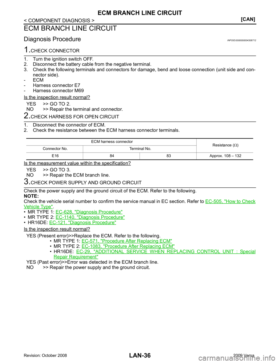
YES >> GO TO 2.
NO >> Repair the terminal and connector. YES >> GO TO 3.
NO >> Repair the ECM branch line. How to Check
Vehicle Type " .
• MR TYPE 1: EC-628, " Diagnosis Procedure "
• MR TYPE 2:
EC-1140, " Diagnosis Procedure "
• HR16DE:
EC-121, " Diagnosis Procedure "
Is the inspection result normal?
YES (Present error)>>Replace the ECM. Refer to the following.
• MR TYPE 1: EC-571, " Procedure After Replacing ECM "
• MR TYPE 2:
EC-1083, " Procedure After Replacing ECM "
• HR16DE:
EC-29, " ADDITIONAL SERVICE WHEN REPLACING CONTROL UNIT : Special
Repair Requirement "
YES (Past error)>>Error was detected in the ECM branch line.
NO >> Repair the power supply and the ground circuit. ECM harness connector
Resistance (Ω)
Connector No. Terminal No.
E16 84 83 Approx. 108 – 132
Page 3442 of 4331
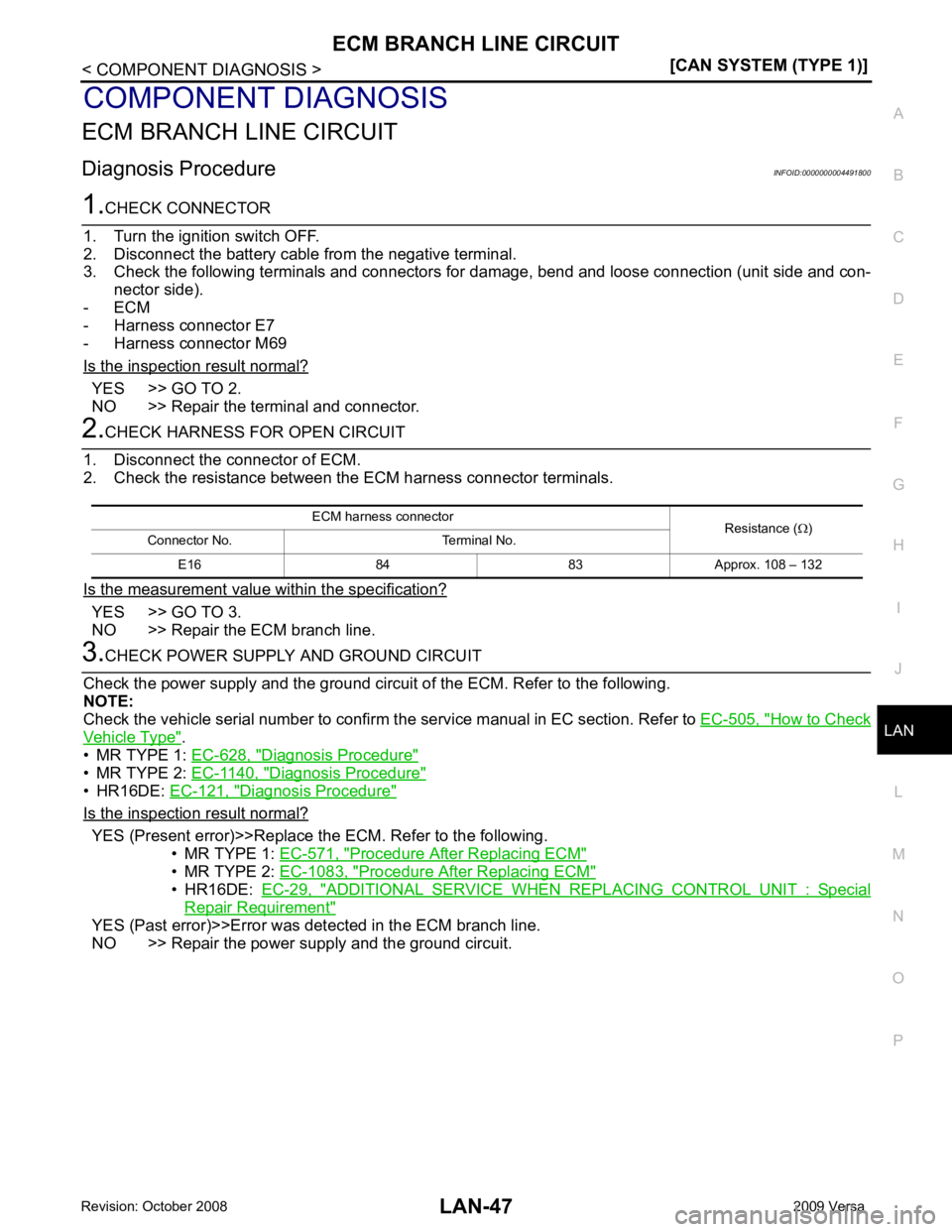
LAN
N
O P
COMPONENT DIAGNOSIS
ECM BRANCH LINE CIRCUIT
Diagnosis Procedure INFOID:0000000004491800YES >> GO TO 2.
NO >> Repair the terminal and connector. YES >> GO TO 3.
NO >> Repair the ECM branch line. How to Check
Vehicle Type " .
• MR TYPE 1: EC-628, " Diagnosis Procedure "
• MR TYPE 2:
EC-1140, " Diagnosis Procedure "
• HR16DE:
EC-121, " Diagnosis Procedure "
Is the inspection result normal?
YES (Present error)>>Replace the ECM. Refer to the following.
• MR TYPE 1: EC-571, " Procedure After Replacing ECM "
• MR TYPE 2:
EC-1083, " Procedure After Replacing ECM "
• HR16DE:
EC-29, " ADDITIONAL SERVICE WHEN REPLACING CONTROL UNIT : Special
Repair Requirement "
YES (Past error)>>Error was det
ected in the ECM branch line.
NO >> Repair the power supply and the ground circuit. ECM harness connector
Resistance (Ω)
Connector No. Terminal No.
E16 84 83 Approx. 108 – 132