2009 NISSAN LATIO door lock
[x] Cancel search: door lockPage 668 of 4331
TRUNK LID OPENER
BL-207
< SERVICE INFORMATION >
C
D E
F
G H
J
K L
M A
B BL
N
O P
OK >> GO TO 2.
NG >> If fuse is blown, be sure to eliminate caus e of malfunction before installing new fuse. Refer to PG-3, " Schematic " .
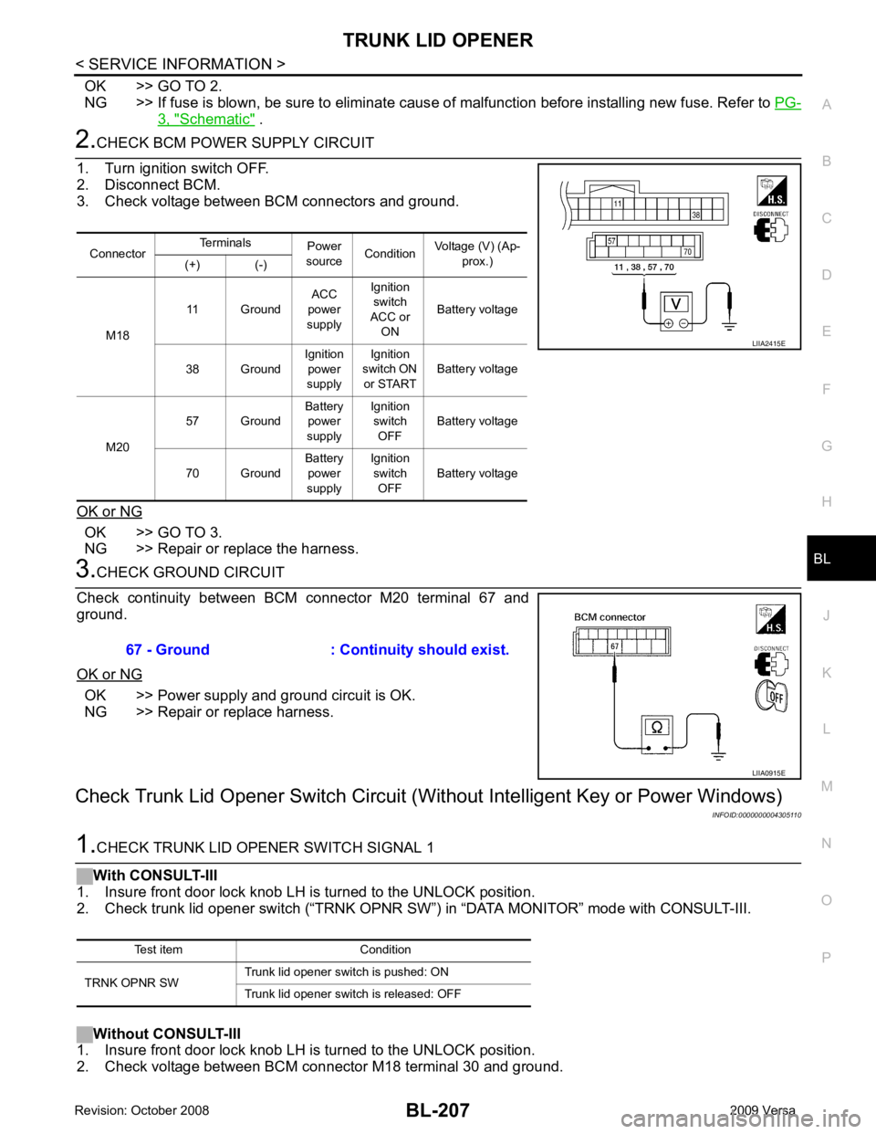
2.
CHECK BCM POWER SUPPLY CIRCUIT
1. Turn ignition switch OFF.
2. Disconnect BCM.
3. Check voltage between BCM connectors and ground.
OK or NG OK >> GO TO 3.
NG >> Repair or replace the harness. 3.
CHECK GROUND CIRCUIT
Check continuity between BCM connector M20 terminal 67 and
ground.
OK or NG OK >> Power supply and ground circuit is OK.
NG >> Repair or replace harness.
Check Trunk Lid Opener Switch Circuit (Wit hout Intelligent Key or Power Windows)
INFOID:00000000043051101.
CHECK TRUNK LID OPENER SWITCH SIGNAL 1
With CONSULT-III
1. Insure front door lock knob LH is turned to the UNLOCK position.
2. Check trunk lid opener switch (“TRNK OPNR SW”) in “DATA MONITOR” mode with CONSULT-III.
Without CONSULT-III
1. Insure front door lock knob LH is turned to the UNLOCK position.
2. Check voltage between BCM connector M18 terminal 30 and ground. Connector
Terminals
Power
source Condition Voltage (V) (Ap-
prox.)
(+) (-)
M18 11 Ground
ACC
power
supply Ignition
switch
ACC or ON Battery voltage
38 Ground Ignition
power
supply Ignition
switch ON
or START Battery voltage
M20 57 Ground
Battery
power
supply Ignition
switch OFF Battery voltage
70 Ground Battery
power
supply Ignition
switch OFF Battery voltage LIIA2415E
67 - Ground : Continuity should exist.
LIIA0915E
Test item Condition
TRNK OPNR SW Trunk lid opener switch is pushed: ON
Trunk lid opener switch is released: OFF
Page 669 of 4331
BL-208< SERVICE INFORMATION >
TRUNK LID OPENER
OK or NG OK >> Trunk lid opener switch is OK.
NG >> GO TO 2 2.
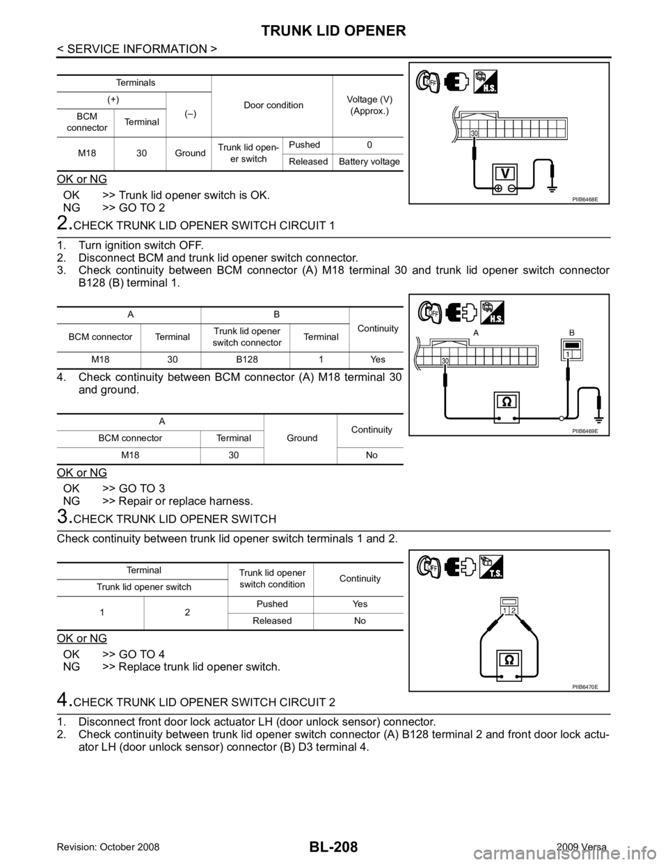
CHECK TRUNK LID OPENER SWITCH CIRCUIT 1
1. Turn ignition switch OFF.
2. Disconnect BCM and trunk lid opener switch connector.
3. Check continuity between BCM connector (A) M18 terminal 30 and trunk lid opener switch connector
B128 (B) terminal 1.
4. Check continuity between BCM connector (A) M18 terminal 30
and ground.
OK or NG OK >> GO TO 3
NG >> Repair or replace harness. 3.
CHECK TRUNK LID OPENER SWITCH
Check continuity between trunk lid opener switch terminals 1 and 2.
OK or NG OK >> GO TO 4
NG >> Replace trunk lid opener switch. 4.
CHECK TRUNK LID OPENER SWITCH CIRCUIT 2
1. Disconnect front door lock actuator LH (door unlock sensor) connector.
2. Check continuity between trunk lid opener switch connector (A) B128 terminal 2 and front door lock actu- ator LH (door unlock sensor) connector (B) D3 terminal 4. Terminals
Door conditionVoltage (V)
(Approx.)
(+)
(–)
BCM
connector Terminal
M18 30 Ground Trunk lid open-
er switch Pushed 0
Released Battery voltage PIIB6468E
A B
Continuity
BCM connector Terminal Trunk lid opener
switch connector Terminal
M18 30 B128 1 Yes
A GroundContinuity
BCM connector Terminal
M18 30 No PIIB6469E
Terminal
Trunk lid opener
switch condition Continuity
Trunk lid opener switch
1 2 Pushed Yes
Released No PIIB6470E
Page 670 of 4331
TRUNK LID OPENER
BL-209
< SERVICE INFORMATION >
C
D E
F
G H
J
K L
M A
B BL
N
O P
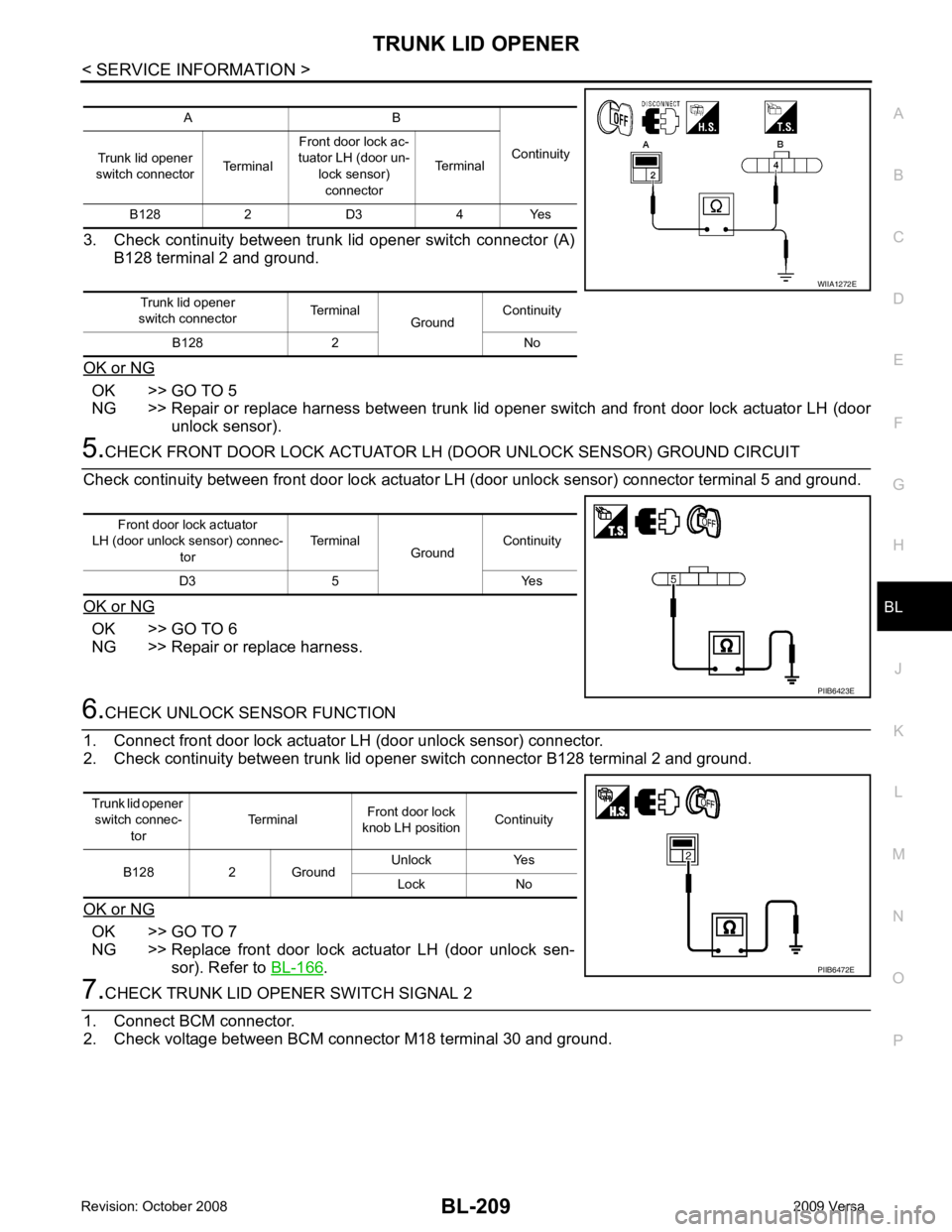
3. Check continuity between trunk lid opener switch connector (A)
B128 terminal 2 and ground.
OK or NG OK >> GO TO 5
NG >> Repair or replace harness between trunk lid opener switch and front door lock actuator LH (door
unlock sensor). 5.
CHECK FRONT DOOR LOCK ACTUATOR LH (DOOR UNLOCK SENSOR) GROUND CIRCUIT
Check continuity between front door lock actuator LH (door unlock sensor) connector terminal 5 and ground.
OK or NG OK >> GO TO 6
NG >> Repair or replace harness. 6.
CHECK UNLOCK SENSOR FUNCTION
1. Connect front door lock actuator LH (door unlock sensor) connector.
2. Check continuity between trunk lid opener switch connector B128 terminal 2 and ground.
OK or NG OK >> GO TO 7
NG >> Replace front door lock actuator LH (door unlock sen- sor). Refer to BL-166 .
7.
CHECK TRUNK LID OPENER SWITCH SIGNAL 2
1. Connect BCM connector.
2. Check voltage between BCM connector M18 terminal 30 and ground. A B
Continuity
Trunk lid opener
switch connector TerminalFront door lock ac-
tuator LH (door un-
lock sensor)connector Terminal
B128 2 D3 4 Yes
Trunk lid opener
switch connector Terminal
GroundContinuity
B128 2 No WIIA1272E
Front door lock actuator
LH (door unlock sensor) connec-
tor Terminal
GroundContinuity
D3 5 Yes PIIB6423E
Trunk lid opener
switch connec- tor Terminal
Front door lock
knob LH position Continuity
B128 2 Ground Unlock Yes
Lock No PIIB6472E
Page 671 of 4331
BL-210< SERVICE INFORMATION >
TRUNK LID OPENER
OK or NG OK >> Check the condition of harness and connector.
NG >> Replace BCM. Refer to BCS-18, " Removal and Installa-
tion of BCM " .
Check Trunk Lid Opener Switch Circuit (W ithout Intelligent Key, with Power Windows)
INFOID:00000000043051111.
CHECK TRUNK LID OPENER SWITCH SIGNAL 1
With CONSULT-III
1. Insure front door lock knob RH is turned to the UNLOCK position.
2. Check trunk lid opener switch (“TRNK OPNR SW ”) in “DATA MONITOR” mode with CONSULT-III.
Without CONSULT-III
1. Insure front door lock knob RH is turned to the UNLOCK position.
2. Check voltage between BCM connector M18 terminal 30 and ground.
OK or NG OK >> Trunk lid opener switch is OK.
NG >> GO TO 2 2.
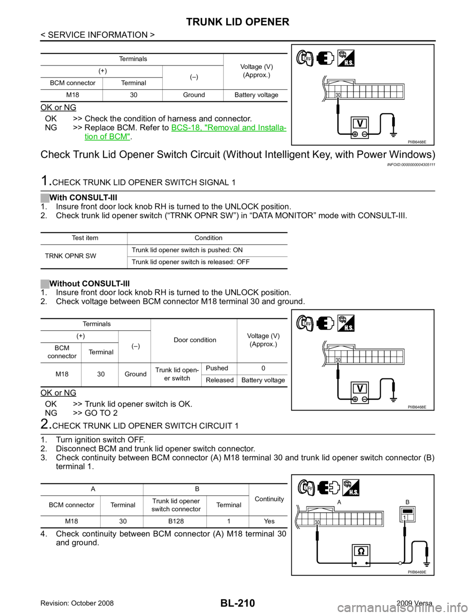
CHECK TRUNK LID OPENER SWITCH CIRCUIT 1
1. Turn ignition switch OFF.
2. Disconnect BCM and trunk lid opener switch connector.
3. Check continuity between BCM connector (A) M18 terminal 30 and trunk lid opener switch connector (B)
terminal 1.
4. Check continuity between BCM connector (A) M18 terminal 30
and ground. Terminals
Voltage (V)
(Approx.)
(+)
(–)
BCM connector Terminal
M18 30 Ground Battery voltage PIIB6468E
Test item Condition
TRNK OPNR SW Trunk lid opener switch is pushed: ON
Trunk lid opener switch is released: OFF Terminals
Door conditionVoltage (V)
(Approx.)
(+)
(–)
BCM
connector Terminal
M18 30 Ground Trunk lid open-
er switch Pushed 0
Released Battery voltage PIIB6468E
A B
Continuity
BCM connector Terminal Trunk lid opener
switch connector Terminal
M18 30 B128 1 Yes PIIB6469E
Page 672 of 4331
TRUNK LID OPENER
BL-211
< SERVICE INFORMATION >
C
D E
F
G H
J
K L
M A
B BL
N
O P
OK or NG OK >> GO TO 3
NG >> Repair or replace harness. 3.
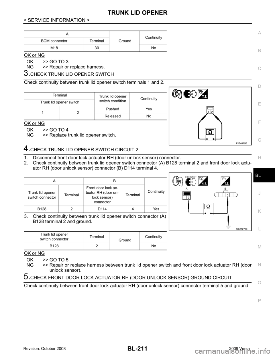
CHECK TRUNK LID OPENER SWITCH
Check continuity between trunk lid opener switch terminals 1 and 2.
OK or NG OK >> GO TO 4
NG >> Replace trunk lid opener switch. 4.
CHECK TRUNK LID OPENER SWITCH CIRCUIT 2
1. Disconnect front door lock actuator RH (door unlock sensor) connector.
2. Check continuity between trunk lid opener switch c onnector (A) B128 terminal 2 and front door lock actu-
ator RH (door unlock sensor) connector (B) D114 terminal 4.
3. Check continuity between trunk lid opener switch connector (A) B128 terminal 2 and ground.
OK or NG OK >> GO TO 5
NG >> Repair or replace harness between trunk lid opener switch and front door lock actuator RH (door
unlock sensor). 5.
CHECK FRONT DOOR LOCK ACTUATOR RH (DOOR UNLOCK SENSOR) GROUND CIRCUIT
Check continuity between front door lock actuator RH (door unlock sensor) connector terminal 5 and ground.
A
GroundContinuity
BCM connector Terminal
M18 30 No Terminal
Trunk lid opener
switch condition Continuity
Trunk lid opener switch
1 2 Pushed Yes
Released No PIIB6470E
A B
Continuity
Trunk lid opener
switch connector TerminalFront door lock ac-
tuator RH (door un- lock sensor)
connector Terminal
B128 2 D114 4 Yes
Trunk lid opener
switch connector Terminal
GroundContinuity
B128 2 No WIIA1271E
Page 673 of 4331
BL-212< SERVICE INFORMATION >
TRUNK LID OPENER
OK or NG OK >> GO TO 6
NG >> Repair or replace harness. 6.
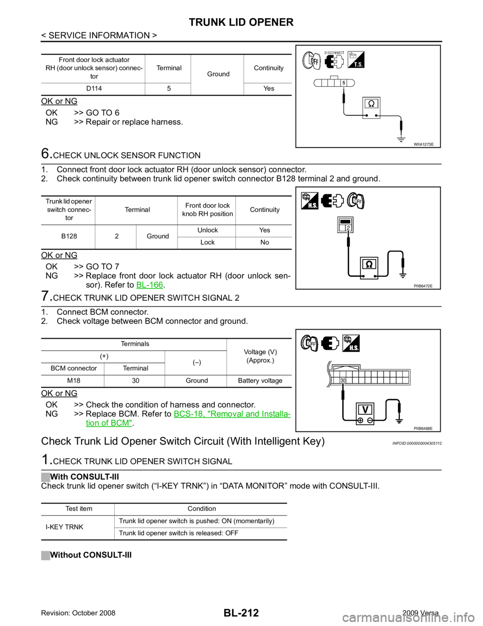
CHECK UNLOCK SENSOR FUNCTION
1. Connect front door lock actuator RH (door unlock sensor) connector.
2. Check continuity between trunk lid opener switch connector B128 terminal 2 and ground.
OK or NG OK >> GO TO 7
NG >> Replace front door lock actuator RH (door unlock sen- sor). Refer to BL-166 .
7.
CHECK TRUNK LID OPENER SWITCH SIGNAL 2
1. Connect BCM connector.
2. Check voltage between BCM connector and ground.
OK or NG OK >> Check the condition of harness and connector.
NG >> Replace BCM. Refer to BCS-18, " Removal and Installa-
tion of BCM " .
Check Trunk Lid Opener Switch Circuit (With Intelligent Key) INFOID:00000000043051121.
CHECK TRUNK LID OPENER SWITCH SIGNAL
With CONSULT-III
Check trunk lid opener switch (“I-KEY TRNK”) in “DATA MONI TOR” mode with CONSULT-III.
Without CONSULT-III Front door lock actuator
RH (door unlock sensor) connec-
tor Terminal
GroundContinuity
D114 5 Yes WIIA1273E
Trunk lid opener
switch connec- tor Terminal
Front door lock
knob RH position Continuity
B128 2 Ground Unlock Yes
Lock No PIIB6472E
Terminals
Voltage (V)
(Approx.)
(+)
(–)
BCM connector Terminal
M18 30 Ground Battery voltage PIIB6468E
Test item Condition
I-KEY TRNK Trunk lid opener switch is pushed: ON (momentarily)
Trunk lid opener switch is released: OFF
Page 675 of 4331
BL-214< SERVICE INFORMATION >
TRUNK LID OPENER
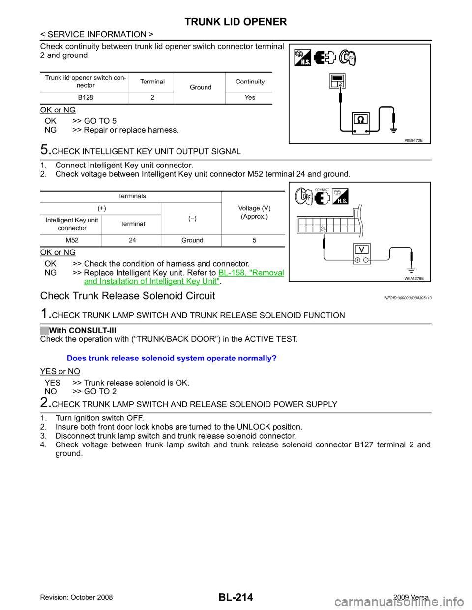
Check continuity between trunk lid opener switch connector terminal
2 and ground.
OK or NG OK >> GO TO 5
NG >> Repair or replace harness. 5.
CHECK INTELLIGENT KEY UNIT OUTPUT SIGNAL
1. Connect Intelligent Key unit connector.
2. Check voltage between Intelligent Key unit connector M52 terminal 24 and ground.
OK or NG OK >> Check the condition of harness and connector.
NG >> Replace Intelligent Key unit. Refer to BL-158, " Removal
and Installation of Intelligent Key Unit " .
Check Trunk Releas e Solenoid Circuit INFOID:00000000043051131.
CHECK TRUNK LAMP SWITCH AND T RUNK RELEASE SOLENOID FUNCTION
With CONSULT-III
Check the operation with (“TRUNK/BACK DOOR”) in the ACTIVE TEST.
YES or NO YES >> Trunk release solenoid is OK.
NO >> GO TO 2 2.
CHECK TRUNK LAMP SWITCH AND RE LEASE SOLENOID POWER SUPPLY
1. Turn ignition switch OFF.
2. Insure both front door lock knobs are turned to the UNLOCK position.
3. Disconnect trunk lamp switch and trunk release solenoid connector.
4. Check voltage between trunk lamp switch and trunk release solenoid connector B127 terminal 2 and ground.
Trunk lid opener switch con-
nector Terminal
GroundContinuity
B128 2 Yes PIIB6472E
Terminals
Voltage (V)(Approx.)
(+)
(–)
Intelligent Key unit
connector Terminal
M52 24 Ground 5 WIIA1279E
Does trunk release solenoid
system operate normally?
Page 680 of 4331
BL
N
O P
System Description
INFOID:0000000004305116
DESCRIPTION
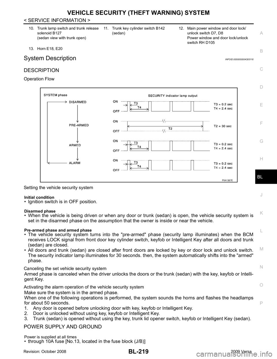
Operation Flow
Setting the vehicle security system Initial condition
• Ignition switch is in OFF position.
Disarmed phase
• When the vehicle is being driven or when any door or tr unk (sedan) is open, the vehicle security system is
set in the disarmed phase on the assumption that the owner is inside or near the vehicle.
Pre-armed phase and armed phase
• The vehicle security system turns into the "pre- armed" phase (security lamp illuminates) when the BCM
receives LOCK signal from front door key cylinder s witch, keyfob or Intelligent Key after all doors and trunk
(sedan) are closed.
• All doors and trunk (sedan) are closed after front door s are locked by key or door lock and unlock switch.
The security indicator lamp illuminates for 30 seconds. t hen, the system automatically shifts into the "armed"
phase.
Canceling the set vehicle security system Armed phase is canceled when the driver unlocks the doors or the trunk (sedan) with the key, keyfob or Intelli-
gent Key.
Activating the alarm operation of the vehicle security system Make sure the system is in the armed phase.
When one of the following operations is performed, the system sounds the horns and flashes the headlamps
for about 50 seconds.
1. Any door is opened before unlocking door with key, keyfob or Intelligent Key.
2. Door is unlocked without using key, keyfob or Intelligent Key.
3. Trunk (sedan) is opened without using the key, trunk lid opener switch, keyfob or Intelligent Key (sedan).
POWER SUPPLY AND GROUND
Power is supplied at all times
• through 10A fuse [No.13, located in the fuse block (J/B)] 10. Trunk lamp switch and trunk release
solenoid B127
(sedan view with trunk open) 11. Trunk key cylinder switch B142
(sedan) 12. Main power window and door lock/
unlock switch D7, D8
Power window and door lock/unlock
switch RH D105
13. Horn E18, E20