Page 643 of 4331

System Description " .
3. Repair or replace any malfunctioning parts. Refer to BL-182, " Trouble Diagnosis Chart by Symptom " .
4. Does back door opener operate normally? If Yes, GO TO 5. If No, GO TO 3.
5. Inspection End.
Trouble Diagnosis Chart by Symptom INFOID:0000000004305090
BCM Power Supply and Gr ound Circuit Inspection INFOID:0000000004678881Test item Content
TRUNK/BACK DOOR This test is able to check back door lock assembly (actuator) unlock operation.
Actuator opens back door lock assembly when “OPEN” on CONSULT-III screen is touched. Symptom Diagnoses/service procedure
Reference
page
Back door opener does not operate.
(Without Intelligent Key or power windows) 1. Check BCM power supply and ground circuit.
BCS-15 2. Check back door opener switch circuit.
BL-183 3. Check back door lock assembly (actuator) circuit.
BL-190 4. Replace BCM.
BCS-18Back door opener does not operate.
(Without Intelligent Key, with power windows) 1. Check BCM power supply and ground circuit.
BCS-15 2. Check back door opener switch circuit.
BL-186 3. Check back door lock assembly (actuator) circuit.
BL-190 4. Replace BCM.
BCS-18Back door opener does not operate.
(With Intelligent Key) 1. Check BCM power supply and ground circuit.
BCS-15 2.
Check Intelligent Key power supply and ground cir-
cuit. BL-126 3. Check back door opener switch circuit.
BL-188 4. Check back door lock assembly (actuator) circuit.
BL-190 5. Replace BCM.
BCS-18
Page 644 of 4331

BACK DOOR LOCK
BL-183
< SERVICE INFORMATION >
C
D E
F
G H
J
K L
M A
B BL
N
O P
OK >> GO TO 2.
NG >> If fuse is blown, be sure to eliminate caus e of malfunction before installing new fuse. Refer to PG-3, " Schematic " .
2.
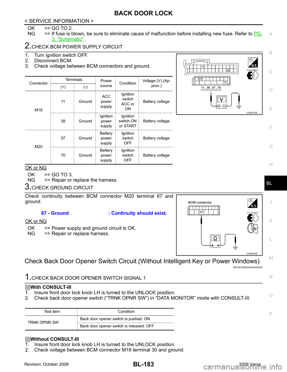
CHECK BCM POWER SUPPLY CIRCUIT
1. Turn ignition switch OFF.
2. Disconnect BCM.
3. Check voltage between BCM connectors and ground.
OK or NG OK >> GO TO 3.
NG >> Repair or replace the harness. 3.
CHECK GROUND CIRCUIT
Check continuity between BCM connector M20 terminal 67 and
ground.
OK or NG OK >> Power supply and ground circuit is OK.
NG >> Repair or replace harness.
Check Back Door Opener S witch Circuit (Without Intellig ent Key or Power Windows)
INFOID:00000000043050921.
CHECK BACK DOOR OPENER SWITCH SIGNAL 1
With CONSULT-III
1. Insure front door lock knob LH is turned to the UNLOCK position.
2. Check back door opener switch (“TRNK OPNR SW ”) in “DATA MONITOR” mode with CONSULT-III.
Without CONSULT-III
1. Insure front door lock knob LH is turned to the UNLOCK position.
2. Check voltage between BCM connector M18 terminal 30 and ground. Connector
Terminals
Power
source Condition Voltage (V) (Ap-
prox.)
(+) (-)
M18 11 Ground
ACC
power
supply Ignition
switch
ACC or ON Battery voltage
38 Ground Ignition
power
supply Ignition
switch ON
or START Battery voltage
M20 57 Ground
Battery
power
supply Ignition
switch OFF Battery voltage
70 Ground Battery
power
supply Ignition
switch OFF Battery voltage LIIA2415E
67 - Ground : Continuity should exist.
LIIA0915E
Test item Condition
TRNK OPNR SW Back door opener switch is pushed: ON
Back door opener switch is released: OFF
Page 646 of 4331
BL
N
O P
3. Check continuity between back door opener switch connector
(A) D408 terminal 2 and ground.
OK or NG OK >> GO TO 5
NG >> Repair or replace harness between back door opener switch and front door lock actuator LH (door
unlock sensor). OK >> GO TO 6
NG >> Repair or replace harness. OK >> GO TO 7
NG >> Replace front door lock actuator LH (door unlock sen- sor). Refer to BL-166 .
Page 647 of 4331

BL-186< SERVICE INFORMATION >
BACK DOOR LOCK
OK or NG OK >> Check the condition of harness and connector.
NG >> Replace BCM. Refer to BCS-18, " Removal and Installa-
tion of BCM " .
Check Back Door Opener Swit ch Circuit (Without Intelligent Key, with Power Windows)
INFOID:00000000043050931.
CHECK BACK DOOR OPENER SWITCH SIGNAL 1
With CONSULT-III
1. Insure front door lock knob RH is turned to the UNLOCK position.
2. Check back door opener switch (“TRNK OPNR SW”) in “DATA MONITOR” mode with CONSULT-III.
Without CONSULT-III
1. Insure front door lock knob RH is turned to the UNLOCK position.
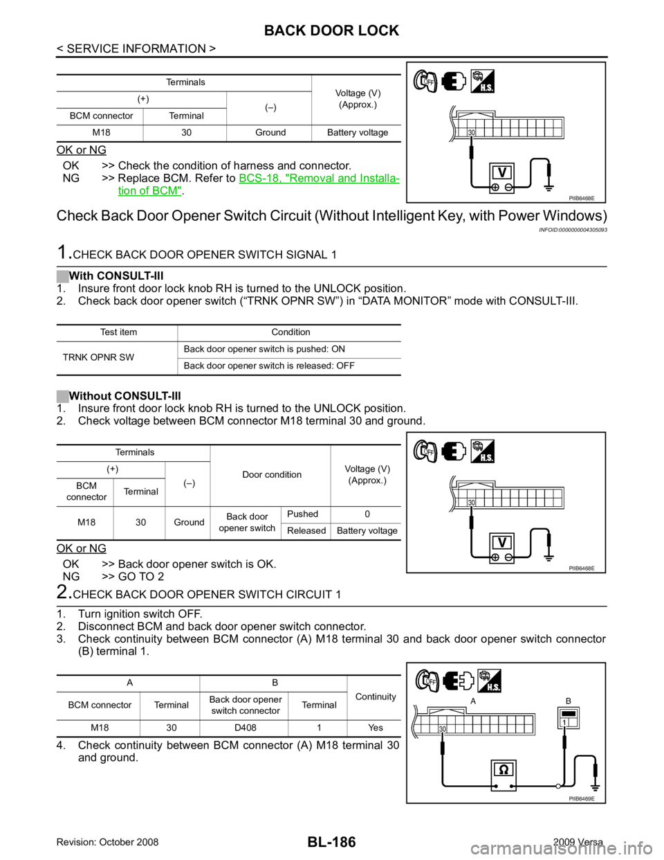
2. Check voltage between BCM connector M18 terminal 30 and ground.
OK or NG OK >> Back door opener switch is OK.
NG >> GO TO 2 2.
CHECK BACK DOOR OPENER SWITCH CIRCUIT 1
1. Turn ignition switch OFF.
2. Disconnect BCM and back door opener switch connector.
3. Check continuity between BCM connector (A) M 18 terminal 30 and back door opener switch connector
(B) terminal 1.
4. Check continuity between BCM connector (A) M18 terminal 30
and ground. Terminals
Voltage (V)
(Approx.)
(+)
(–)
BCM connector Terminal
M18 30 Ground Battery voltage PIIB6468E
Test item Condition
TRNK OPNR SW Back door opener switch is pushed: ON
Back door opener switch is released: OFF Terminals
Door conditionVoltage (V)
(Approx.)
(+)
(–)
BCM
connector Terminal
M18 30 Ground Back door
opener switch Pushed 0
Released Battery voltage PIIB6468E
A B
Continuity
BCM connector Terminal Back door opener
switch connector Terminal
M18 30 D408 1 Yes PIIB6469E
Page 648 of 4331
BL
N
O P
OK or NG OK >> GO TO 3
NG >> Repair or replace harness. OK >> GO TO 4
NG >> Replace back door opener switch. OK >> GO TO 5
NG >> Repair or replace harness between back door opener switch and front door lock actuator RH (door unlock sensor). Terminal
Back door opener
switch condition Continuity
Back door opener switch
1 2 Pushed Yes
Released No
Page 649 of 4331

BL-188< SERVICE INFORMATION >
BACK DOOR LOCK
OK or NG OK >> GO TO 6
NG >> Repair or replace harness. 6.
CHECK UNLOCK SENSOR FUNCTION
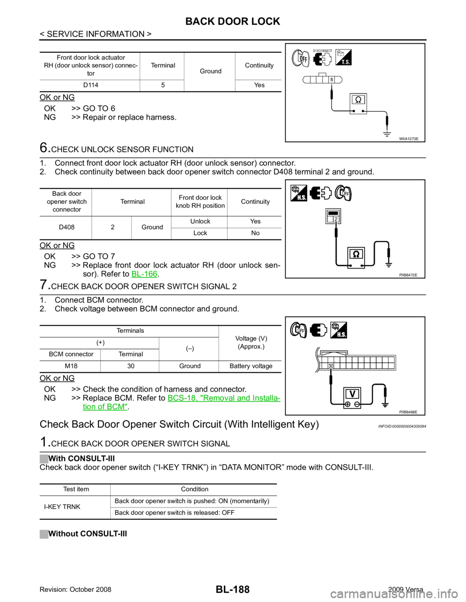
1. Connect front door lock actuator RH (door unlock sensor) connector.
2. Check continuity between back door opener switch connector D408 terminal 2 and ground.
OK or NG OK >> GO TO 7
NG >> Replace front door lock actuator RH (door unlock sen- sor). Refer to BL-166 .
7.
CHECK BACK DOOR OPENER SWITCH SIGNAL 2
1. Connect BCM connector.
2. Check voltage between BCM connector and ground.
OK or NG OK >> Check the condition of harness and connector.
NG >> Replace BCM. Refer to BCS-18, " Removal and Installa-
tion of BCM " .
Check Back Door Opener Switch Circuit (With Intelligent Key) INFOID:00000000043050941.
CHECK BACK DOOR OPENER SWITCH SIGNAL
With CONSULT-III
Check back door opener switch (“I-KEY TRNK”) in “DATA MONITOR” mode with CONSULT-III.
Without CONSULT-III Front door lock actuator
RH (door unlock sensor) connec-
tor Terminal
GroundContinuity
D114 5 Yes WIIA1273E
Back door
opener switch connector Terminal
Front door lock
knob RH position Continuity
D408 2 Ground Unlock Yes
Lock No PIIB6472E
Terminals
Voltage (V)
(Approx.)
(+)
(–)
BCM connector Terminal
M18 30 Ground Battery voltage PIIB6468E
Test item Condition
I-KEY TRNK Back door opener switch is pushed: ON (momentarily)
Back door opener switch is released: OFF
Page 651 of 4331

BL-190< SERVICE INFORMATION >
BACK DOOR LOCK
Check continuity between back door opener switch connector termi-
nal 2 and ground.
OK or NG OK >> GO TO 5
NG >> Repair or replace harness. 5.
CHECK INTELLIGENT KEY UNIT OUTPUT SIGNAL
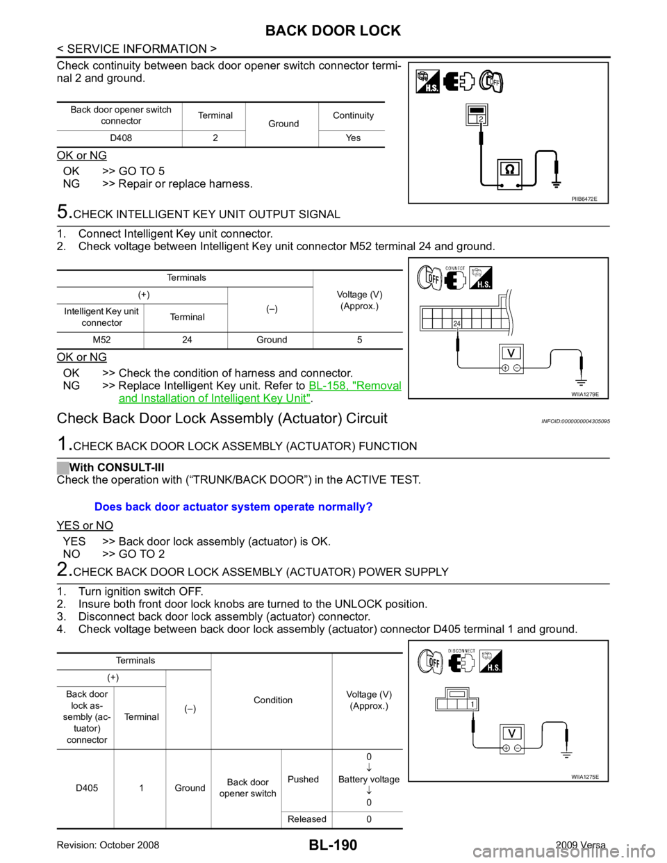
1. Connect Intelligent Key unit connector.
2. Check voltage between Intelligent Key unit connector M52 terminal 24 and ground.
OK or NG OK >> Check the condition of harness and connector.
NG >> Replace Intelligent Key unit. Refer to BL-158, " Removal
and Installation of Intelligent Key Unit " .
Check Back Door Lock Asse mbly (Actuator) Circuit INFOID:00000000043050951.
CHECK BACK DOOR LOCK ASSE MBLY (ACTUATOR) FUNCTION
With CONSULT-III
Check the operation with (“TRUNK/BACK DOOR”) in the ACTIVE TEST.
YES or NO YES >> Back door lock assembly (actuator) is OK.
NO >> GO TO 2 2.
CHECK BACK DOOR LOCK ASSEMB LY (ACTUATOR) POWER SUPPLY
1. Turn ignition switch OFF.
2. Insure both front door lock knobs are turned to the UNLOCK position.
3. Disconnect back door lock assembly (actuator) connector.
4. Check voltage between back door lock assembly (actuator) connector D405 terminal 1 and ground. Back door opener switch
connector Terminal
GroundContinuity
D408 2 Yes PIIB6472E
Terminals
Voltage (V)(Approx.)
(+)
(–)
Intelligent Key unit
connector Terminal
M52 24 Ground 5 WIIA1279E
Does back door actuator system operate normally?
Terminals
ConditionVoltage (V)
(Approx.)
(+)
(–)
Back door
lock as-
sembly (ac-
tuator)
connector Terminal
D405 1 Ground Back door
opener switch Pushed 0
↓
Battery voltage ↓0
Released 0 WIIA1275E
Page 652 of 4331
BL
N
O P
OK or NG OK >> GO TO 3
NG >> GO TO 4 OK >> Replace back door lock assembly (actuator). Refer to
BL-172 .
NG >> Repair or replace harness. OK >> GO TO 5
NG >> Repair or replace harness between BCM and back door lock assembly (actuator). OK >> Check the condition of harness and connector.
NG >> Replace BCM. Refer to BCS-18, " Removal and Installation of BCM " .
Back door lock assembly (actua-
tor) connector Terminal
GroundContinuity
D405 2 Yes