2009 NISSAN LATIO check engine
[x] Cancel search: check enginePage 957 of 4331

CVT
N
O P
Do not start engine.
6. Select “SELF-DIAG RESULTS”.
7. Shift the selector lever to “R” position.
8. Depress slightly the accelerator pedal (Pedal angle: 2/8) while depressing the brake pedal.
9. Perform “ERASE”.
10. Shift the selector lever to “R” position afte r replacing TCM. Turn the ignition switch OFF.
11. Wait approximately 10 minutes after turning the ignition switch OFF.
12. Turn the ignition switch ON while shifting the selector lever to “R” position. CAUTION:
Do not start engine.
13. Select “CALIBRATION DATA”.
14. Check that the value on “CALIBRATION DATA” is same as the data after erasing "Calibration Data". • Restart the procedure from step 3 if the values are not same.
15. Shift the selector lever to “P” position.
16. Check that the shift position indicator in the combi nation meter turns ON (It indicates approximately 1 or 2
seconds after shifting the selector lever to “P” position.)
• Check the following items if the shift position indicato r does not turn ON. Repair or replace the shift posi-
tion indicator if necessary.
- The harness between TCM and ROM ASSY in the transaxle assembly is open or short.
- Cable disconnected, loosen, or bent from the connector housing.
- Power supply and ground of TCM. Refer to CVT-125, " Description " .
PATTERN C 1. Replace the transaxle assembly first, and then replace TCM.
2. Perform the service of “PATTERN A”. (Perform the service of “Pattern B” if TCM is replaced first.)
Removal and Installation Proc edure for CVT Unit Connector INFOID:0000000004666857
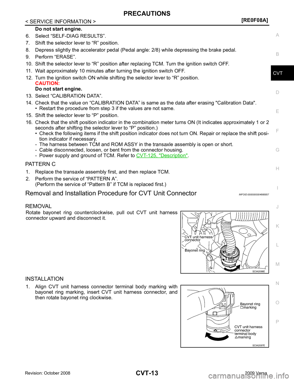
REMOVAL Rotate bayonet ring counterclockwise, pull out CVT unit harness
connector upward and disconnect it.
INSTALLATION 1. Align CVT unit harness connector terminal body marking with bayonet ring marking, insert CVT unit harness connector, and
then rotate bayonet ring clockwise.
Page 961 of 4331

CVT
N
O P
CVT FLUID
Checking CVT Fluid INFOID:0000000004666862
FLUID LEVEL CHECK Fluid level should be checked with the fluid warmed up to 50 ° to 80 °C (122 ° to 176 °F).
1. Check for fluid leakage.
2. With the engine warmed up, drive the vehicle to warm up the CVT fluid. When ambient temperature is 20 °C (68 °F), it takes
about 10 minutes for the CVT fluid to warm up to 50 ° to 80 °C
(122 ° to 176 °F).
3. Park the vehicle on a level surface and set the parking brake.
4. With engine at idle, while depressing brake pedal, move the selector lever throughout the entire shift range and return it to
the “P” position.
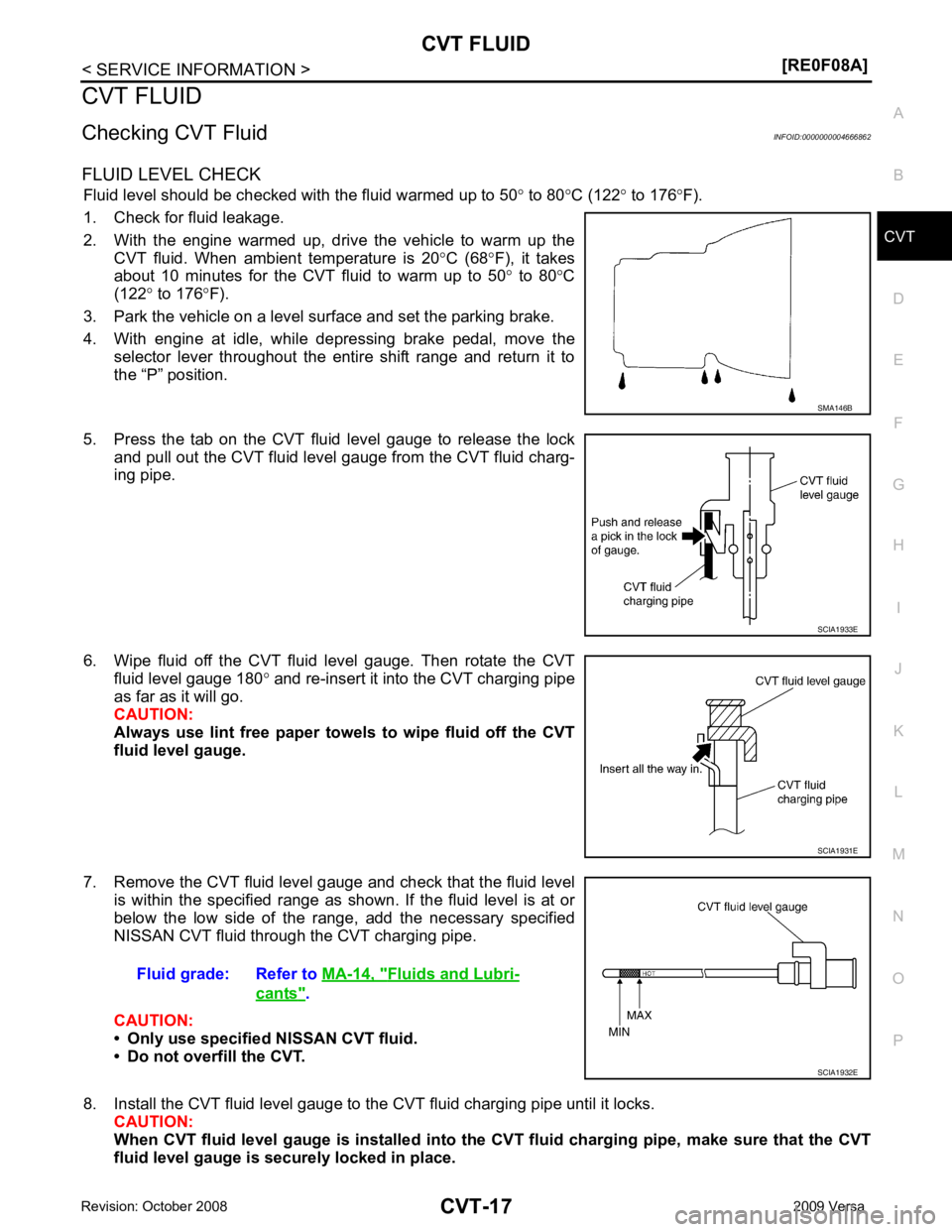
5. Press the tab on the CVT fluid level gauge to release the lock and pull out the CVT fluid level gauge from the CVT fluid charg-
ing pipe.
6. Wipe fluid off the CVT fluid level gauge. Then rotate the CVT fluid level gauge 180 ° and re-insert it into the CVT charging pipe
as far as it will go.
CAUTION:
Always use lint free paper towels to wipe fluid off the CVT
fluid level gauge.
7. Remove the CVT fluid level gauge and check that the fluid level is within the specified range as shown. If the fluid level is at or
below the low side of the range, add the necessary specified
NISSAN CVT fluid through the CVT charging pipe.
CAUTION:
• Only use specified NISSAN CVT fluid.
• Do not overfill the CVT.
8. Install the CVT fluid level gauge to the CVT fluid charging pipe until it locks. CAUTION:
When CVT fluid level gauge is installed into the CVT fluid charging pipe, make sure that the CVT
fluid level gauge is securely locked in place. Fluids and Lubri-
cants " .
Page 976 of 4331
![NISSAN LATIO 2009 Service Repair Manual CVT-32< SERVICE INFORMATION >
[RE0F08A]
ON BOARD DIAGNOSTIC (OBD) SYSTEM
The MIL is located on the instrument panel.
1. The MIL will light up when the ignition switch is turned ON with- out the engine NISSAN LATIO 2009 Service Repair Manual CVT-32< SERVICE INFORMATION >
[RE0F08A]
ON BOARD DIAGNOSTIC (OBD) SYSTEM
The MIL is located on the instrument panel.
1. The MIL will light up when the ignition switch is turned ON with- out the engine](/manual-img/5/57359/w960_57359-975.png)
CVT-32< SERVICE INFORMATION >
[RE0F08A]
ON BOARD DIAGNOSTIC (OBD) SYSTEM
The MIL is located on the instrument panel.
1. The MIL will light up when the ignition switch is turned ON with- out the engine running. This is a bulb check.
• If the MIL does not light up, refer to DI-20, " Schematic " , or see
EC-1010, " Wiring Diagram " .
2. When the engine is started, the MIL should go off. If the MIL remains on, the on board diagnostic system has
detected an engine system malfunction. SEF217U
Page 978 of 4331
![NISSAN LATIO 2009 Service Repair Manual CVT-34< SERVICE INFORMATION >
[RE0F08A]
TROUBLE DIAGNOSIS
If an unexpected signal is sent from the solenoid to t he TCM, the CVT lock-up select solenoid is turned OFF to
cancel the lock-up.
TCM Power NISSAN LATIO 2009 Service Repair Manual CVT-34< SERVICE INFORMATION >
[RE0F08A]
TROUBLE DIAGNOSIS
If an unexpected signal is sent from the solenoid to t he TCM, the CVT lock-up select solenoid is turned OFF to
cancel the lock-up.
TCM Power](/manual-img/5/57359/w960_57359-977.png)
CVT-34< SERVICE INFORMATION >
[RE0F08A]
TROUBLE DIAGNOSIS
If an unexpected signal is sent from the solenoid to t he TCM, the CVT lock-up select solenoid is turned OFF to
cancel the lock-up.
TCM Power Supply (Memory Back-up)
Transaxle assembly is protected by limiting the engine torque when the memory back-up power supply (for
controlling) from the battery is not supplied to TCM. Normal statues is restored when turning the ignition switch
OFF to ON after the normal power supply.
How to Perform Trouble Diagnosis for Quick and Accurate Repair INFOID:0000000004666882
INTRODUCTION
The TCM receives a signal from the vehicle speed sensor, PNP switch and provides shift control or lock-up
control via CVT solenoid valves.
The TCM also communicates with the ECM by means of a signal
sent from sensing elements used wit h the OBD-related parts of the
CVT system for malfunction-diagnostic purposes. The TCM is capa-
ble of diagnosing malfunctioning parts while the ECM can store mal-
functions in its memory.
Input and output signals must always be correct and stable in the
operation of the CVT system. The CVT system must be in good
operating condition and be free of valve seizure, solenoid valve mal-
function, etc.
It is much more difficult to diagnose an error that occurs intermit-
tently rather than continuously. Mo st intermittent errors are caused
by poor electric connections or improper wiring. In this case, careful
checking of suspected circuits ma y help prevent the replacement of
good parts.
A visual check only may not find the cause of the errors. A road test
with CONSULT-III (or GST) or a circuit tester connected should be
performed. Follow the "WORK FLOW" .
Before undertaking actual checks, take a few minutes to talk with a
customer who approaches with a driveability complaint. The cus-
tomer can supply good information about such errors, especially
intermittent ones. Find out what symptoms are present and under
what conditions they occur. A “DIAGNOSTIC WORKSHEET” as
shown on the example (Refer to "Diagnostic Worksheet Chart" )
should be used.
Start your diagnosis by looking for “conventional” errors first. This will
help troubleshoot driveability errors on an electronically controlled
engine vehicle.
Also check related Service bulletins.
WORK FLOW
A good understanding of the malfunction conditions can make troubleshooting faster and more accurate.
In general, each customer feels differently about a malf unction. It is important to fully understand the symp-
toms or conditions for a customer complaint.
Make good use of the two sheets provided, "Informati on From Customer" and "Diagnostic Worksheet Chart" ,
to perform the best troubleshooting possible.
Work Flow Chart SAT631IB
SAT632I
SEF234G
Page 981 of 4331

CVT
N
O P
4
�†
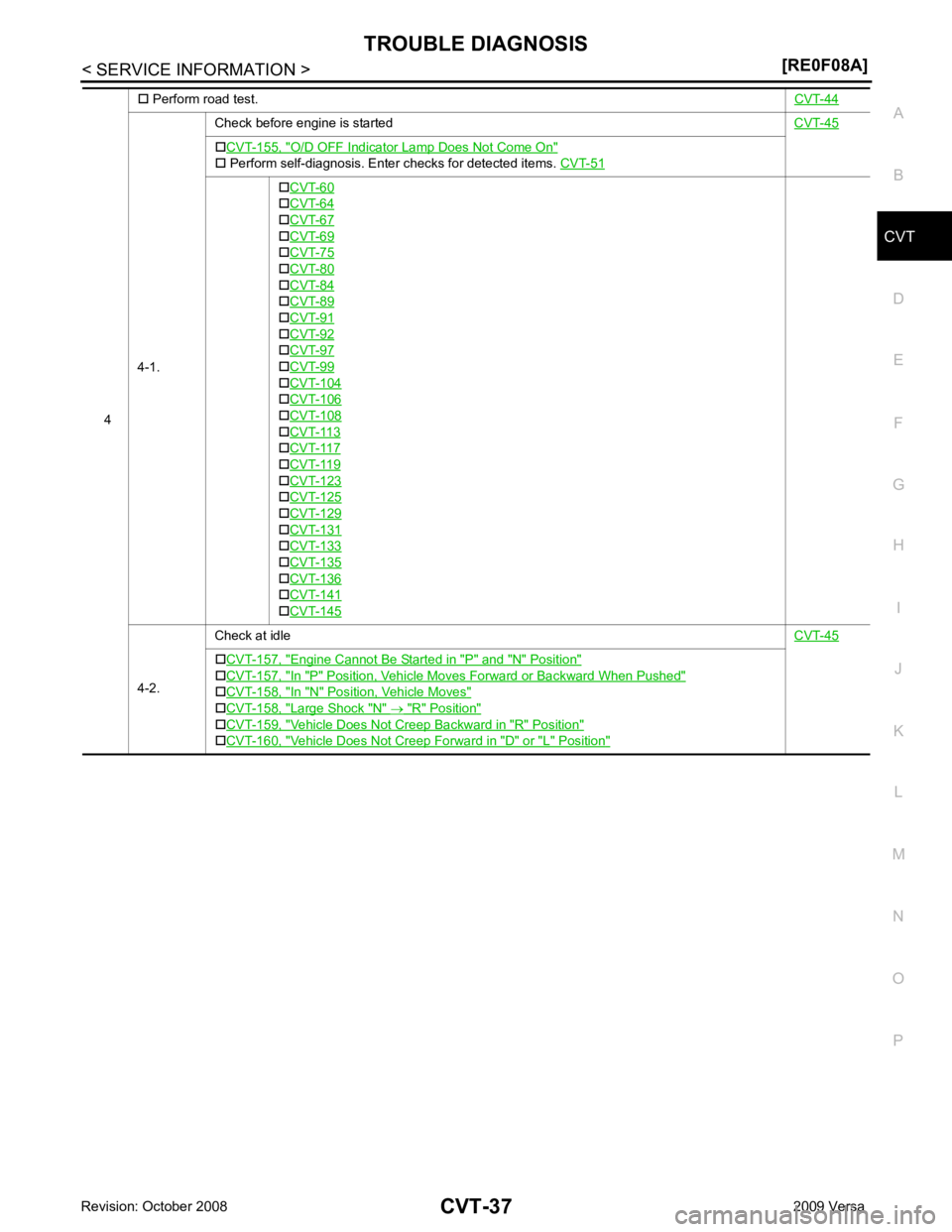
Perform road test. CVT-444-1.
Check before engine is started
CVT-45O/D OFF Indicator Lamp
Does Not Come On "
4-2.
Check at idle
CVT-45Engine Cannot Be Started in "P" and "N" Position "
In "P" Position, Vehicle Moves Forward or Backward When Pushed "
In "N" Position, Vehicle Moves "
Large Shock "N" "
Vehicle Does Not Creep Backward in "R" Position "
Vehicle Does Not Creep Forward in "D" or "L" Position "
Page 982 of 4331

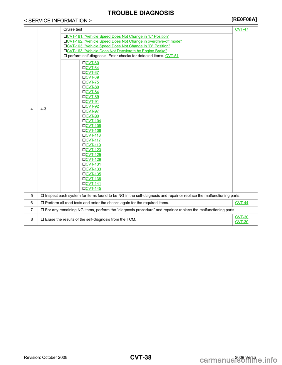
Vehicle Speed Does Not Change in "L" Position "
Vehicle Speed Does Not Change in overdrive-off mode "
Vehicle Speed Does Not Change in "D" Position "
Vehicle Does Not Decelerate by Engine Brake "
5
�† Inspect each system for items found to be NG in the self-diagnosis and repair or replace the malfunctioning parts.
6 �† Perform all road tests and enter the checks again for the required items. CVT-447
�† For any remaining NG items, perform the “diagnosis procedure” and repair or replace the malfunctioning parts.
8 �† Erase the results of the self-diagnosis from the TCM. CVT-30 ,
CVT-30
Page 985 of 4331
![NISSAN LATIO 2009 Service Repair Manual TROUBLE DIAGNOSIS
CVT-41
< SERVICE INFORMATION >
[RE0F08A] D
E
F
G H
I
J
K L
M A
B CVT
N
O P
• Inspect for fluid leakage and check the fluid level. Refer to
CVT-17, " Checking CVT Fluid " .
Fluid NISSAN LATIO 2009 Service Repair Manual TROUBLE DIAGNOSIS
CVT-41
< SERVICE INFORMATION >
[RE0F08A] D
E
F
G H
I
J
K L
M A
B CVT
N
O P
• Inspect for fluid leakage and check the fluid level. Refer to
CVT-17, " Checking CVT Fluid " .
Fluid](/manual-img/5/57359/w960_57359-984.png)
TROUBLE DIAGNOSIS
CVT-41
< SERVICE INFORMATION >
[RE0F08A] D
E
F
G H
I
J
K L
M A
B CVT
N
O P
• Inspect for fluid leakage and check the fluid level. Refer to
CVT-17, " Checking CVT Fluid " .
Fluid Condition Check Inspect the fluid condition.
STALL TEST
Stall Test Procedure 1. Inspect the amount of engine oil. Replenish the engine oil if necessary.
2. Drive for about 10 minutes to warm up the vehicle so that the CVT fluid temperature is 50 to 80 °C (122 to 176 °F). Inspect the
amount of CVT fluid. Replenish if necessary.
3. Securely engage the parking brake so that the tires do not turn.
4. Install a tachometer where it can be seen by driver during test. •It is good practice to mark the point of specified engine
rpm on indicator.
5. Start engine, apply foot brake, and place selector lever in “D” position.Fluid status Conceivable cause Required operation
Varnished (viscous
varnish state) Clutch, brake
scorched Replace the CVT fluid and check the
CVT main unit and the vehicle for
malfunctions (wire harnesses, cool-
er pipes, etc.)
Milky white or
cloudy Water in the fluidReplace the CVT fluid and check for
places where water is getting in.
Large amount of
metal powder mixed
in Unusual wear of
sliding parts within
CVT Replace the CVT fluid and check for
improper operation of the CVT. SAT638A
SAT647B
SAT513G
SAT775B
Page 988 of 4331
![NISSAN LATIO 2009 Service Repair Manual CVT-44< SERVICE INFORMATION >
[RE0F08A]
TROUBLE DIAGNOSIS
Road Test INFOID:0000000004666886
DESCRIPTION
• The purpose of the test is to determine overall performance of CVT and analyze causes of pro NISSAN LATIO 2009 Service Repair Manual CVT-44< SERVICE INFORMATION >
[RE0F08A]
TROUBLE DIAGNOSIS
Road Test INFOID:0000000004666886
DESCRIPTION
• The purpose of the test is to determine overall performance of CVT and analyze causes of pro](/manual-img/5/57359/w960_57359-987.png)
CVT-44< SERVICE INFORMATION >
[RE0F08A]
TROUBLE DIAGNOSIS
Road Test INFOID:0000000004666886
DESCRIPTION
• The purpose of the test is to determine overall performance of CVT and analyze causes of problems.
• The road test consists of the following three parts:
1. “Check Before Engine Is Started” CVT-45 .
2. “Check at Idle” CVT-45 .
3. “Cruise Test” CVT-47 .
Judgement Possible cause
Idle speed Low for all positions
(“P”, “R”, “N”, “D”, “L”) Possible causes include malfunctions in the pressure supply system and low oil pump output.
For example
• Oil pump wear
• Pressure regulator valve or plug sticking or spring fatigue
• Oil strainer ⇒ oil pump ⇒ pressure regulator valve passage oil leak
• Engine idle speed too low
Only low for a specific
position Possible causes include an oil pressure leak in a passage or device related to the position after
the pressure is distributed by the manual valve.
High Possible causes include a sensor malfunction or malfunction in the line pressure adjustment
function.
For example
• Accelerator pedal position signal malfunction
• CVT fluid temperature sensor malfunction
• Pressure control solenoid A (line pressure solenoid) malfunction (sticking in OFF state, filter
clog, cut line)
• Pressure regulator valve or plug sticking
Stall speed Line pressure does
not rise higher than
the line pressure for
idle. Possible causes include a sensor malfunction or malfunction in the pressure adjustment func-
tion.
For example
• Accelerator pedal position signal malfunction
• TCM malfunction
• Pressure control solenoid A (line pressure solenoid) malfunction (shorting, sticking in ON state)
• Pressure regulator valve or plug sticking
The pressure rises,
but does not enter the
standard position. Possible causes include malfunctions in the pressure supply system and malfunction in the pres-
sure adjustment function.
For example
• Accelerator pedal position signal malfunction
• Pressure control solenoid A (line pressure solenoid) malfunction (sticking, filter clog)
• Pressure regulator valve or plug sticking
Only low for a specific
position Possible causes include an oil pressure leak in a passage or device related to the position after
the pressure is distributed by the manual valve. SAT786A