2009 NISSAN LATIO steering wheel
[x] Cancel search: steering wheelPage 4116 of 4331

RSU
N
O P
NOISE, VIBRATION AND HARSHN
ESS (NVH) TROUBLESHOOTING
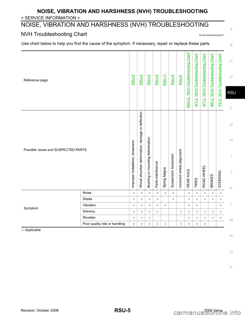
NVH Troubleshooting Chart INFOID:0000000004305877
Use chart below to help you find the cause of the symptom. If necessary, repair or replace these parts.
× : ApplicableReference pageRSU-8RSU-9RSU-9RSU-9RSU-11RSU-8RSU-6
RSU-5, "
NVH Troubleshooting Chart
"
WT-5, "
NVH Troubleshooting Chart
"
WT-5, "
NVH Troubleshooting Chart
"
BR-5, "
NVH Troubleshooting Chart
"
PS-5, "
NVH Troubleshooting Chart
" Possible cause and SUSPECTED PARTS
Improper installation, looseness
Shock absorber deformation, damage or deflection
Bushing or mounting deterioration
Parts interference
Spring fatigue
Suspension looseness
Incorrect wheel alignment
REAR AXLE
TIRES
ROAD WHEEL
BRAKES
STEERING
Symptom Noise
× × × × × × × × × × ×
Shake × × × × × × × × × ×
Vibration × × × × × × × ×
Shimmy × × × × × × × × × ×
Shudder × × × × × × × ×
Poor quality ride or handling × × × × × × × × ×
Page 4117 of 4331

.
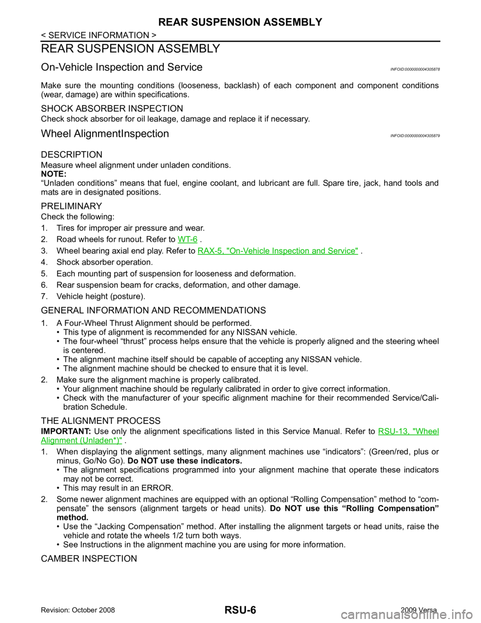
3. Wheel bearing axial end play. Refer to RAX-5, " On-Vehicle Inspection and Service " .
4. Shock absorber operation.
5. Each mounting part of suspension for looseness and deformation.
6. Rear suspension beam for cracks, deformation, and other damage.
7. Vehicle height (posture).
GENERAL INFORMATION AND RECOMMENDATIONS
1. A Four-Wheel Thrust Alignment should be performed. • This type of alignment is recommended for any NISSAN vehicle.
• The four-wheel “thrust” process helps ensure that the vehicle is properly aligned and the steering wheel
is centered.
• The alignment machine itself should be ca pable of accepting any NISSAN vehicle.
• The alignment machine should be checked to ensure that it is level.
2. Make sure the alignment machine is properly calibrated. • Your alignment machine should be regularly calibrated in order to give correct information.
• Check with the manufacturer of your specific al ignment machine for their recommended Service/Cali-
bration Schedule.
THE ALIGNMENT PROCESS
IMPORTANT: Use only the alignment specifications listed in this Service Manual. Refer to RSU-13, " Wheel
Alignment (Unladen*) " .
1. When displaying the alignment settings, many alignm ent machines use “indicators”: (Green/red, plus or
minus, Go/No Go). Do NOT use these indicators.
• The alignment specifications programmed into your alignment machine that operate these indicators
may not be correct.
• This may result in an ERROR.
2. Some newer alignment machines are equipped with an optional “Rolling Compensation” method to “com- pensate” the sensors (alignment targets or head units). Do NOT use this “Rolling Compensation”
method.
• Use the “Jacking Compensation” method. After inst alling the alignment targets or head units, raise the
vehicle and rotate the wheels 1/2 turn both ways.
• See Instructions in the alignment machine you are using for more information.
CAMBER INSPECTION
Page 4125 of 4331

SB
N
O P
CONTENTS
SEAT BELTS
PRECAUTION ....... ........................................2
PRECAUTIONS .............................................. .....2
Precaution for Supplemental Restraint System
(SRS) "AIR BAG" and "SEAT BELT PRE-TEN-
SIONER" ............................................................. ......
2
Precaution Necessary fo r Steering Wheel Rota-
tion After Battery Disconnect ............................... ......
2
Precaution for Seat Belt Service ......................... ......2
ON-VEHICLE REPAIR .... ..............................4 SEAT BELTS .....................................................
4
Removal and Installation of Front Seat Belt ........ .....4
Removal and Installation of Rear Seat Belt ..............6
Seat Belt Inspection ............................................. .....8
LATCH (LOWER ANCHORS AND TETHER
FOR CHILDREN) SYSTEM ............................... 11
Removal and Installation ..................................... ....11
TOP TETHER STRAP CHILD RESTRAINT ..... 12
Removal and Installation ..................................... ....12
Page 4137 of 4331

SC
N
O P
CONTENTS
STARTING & CHARGING SYSTEM
SERVICE INFORMATION .. ..........................2
PRECAUTIONS .............................................. .....2
Precaution for Supplemental Restraint System
(SRS) "AIR BAG" and "SEAT BELT PRE-TEN-
SIONER" ............................................................. ......
2
Precaution Necessary fo r Steering Wheel Rota-
tion After Battery Disconnect ............................... ......
2
PREPARATION .............................................. .....4
Special Service Tool ........................................... ......4
Commercial Service Tool .................................... ......4
BATTERY ....................................................... .....5
How to Handle Ba ttery ........................................ ......5
Trouble Diagnosis with Battery Service Center ... ......7
Removal and Installation ...........................................7
Required Procedure After Battery Disconnection ......8
STARTING SYSTEM ...................................... .....9 System Description ..............................................
.....9
Wiring Diagram - START - ................................... ....11
Trouble Diagnosis with Multitasking Battery Diag-
nostic Station ....................................................... ....
16
Removal and Installation HR16DE ...................... ....19
Removal and Installation MR18DE ...................... ....20
CHARGING SYSTEM ....................................... 21
System Description .............................................. ....21
Wiring Diagram - CHARGE - ............................... ....22
Trouble Diagnosis with Multitasking Battery Diag-
nostic Station ....................................................... ....
22
Removal and Installation ..................................... ....25
SERVICE DATA AND SPECIFICATIONS
(SDS) ................................................................. 27
Battery ................................................................. ....27
Starter .................................................................. ....27
Generator ............................................................ ....27
Page 4164 of 4331

SE
N
O P
CONTENTS
SEAT
SERVICE INFORMATION .. ..........................2
PRECAUTIONS .............................................. .....2
Precaution for Supplemental Restraint System
(SRS) "AIR BAG" and "SEAT BELT PRE-TEN-
SIONER" ............................................................. ......
2
Precaution Necessary fo r Steering Wheel Rota-
tion After Battery Disconnect ............................... ......
2
Service Notice ..................................................... ......2
Precaution ........................................................... ......3
PREPARATION .............................................. .....4
Special Service Tool ........................................... ......4
Commercial Service Tool .................................... ......4
SQUEAK AND RATTLE TROUBLE DIAG-
NOSES ........................ ........................................5
Work Flow ........................................................... ......5 Generic Squeak and Rattle Troubleshooting .......
.....7
Diagnostic Worksheet .......................................... .....9
FRONT SEAT .................................................... 11
Driver Seat ........................................................... ....11
Passenger Seat ................................................... ....12
Removal and Installation ..................................... ....12
Disassembly and Assembly ................................. ....13
REAR SEAT ...................................................... 15
Component Parts Drawing .................................. ....15
Removal and Installation ..................................... ....16
Disassembly and Assembly ................................. ....18
Component Parts Drawing .................................. ....21
Removal and Installation ..................................... ....22
Disassembly and Assembly ................................. ....24
Removal and Installation ..................................... ....26
Disassembly and Assembly ................................. ....26
Page 4191 of 4331

SRS
N
O P
CONTENTS
SUPPLEMENTAL RESTRAINT SYSTEM (SRS)
PRECAUTION ....... ........................................2
PRECAUTIONS .............................................. .....2
Precaution for Supplemental Restraint System
(SRS) "AIR BAG" and "SEAT BELT PRE-TEN-
SIONER" ............................................................. ......
2
Precaution for SRS "AIR BAG" and "SEAT BELT
PRE-TENSIONER" Service ................................ ......
2
Precaution Necessary fo r Steering Wheel Rota-
tion After Battery Disconnect ............................... ......
2
Occupant Classification System Precaution ....... ......3
SYMPTOM DIAGNOSIS ..... ..........................4
SUPPLEMENTAL RESTRAINT SYSTEM
(SRS) .............................................................. .....
4
SRS Configuration .............................................. ......4
Driver Air Bag Module ......................................... ......5
Front Passenger Air Bag Module ..............................5
Front Side Air Bag ............................................... ......5
Side Curtain Air Bag ............................................ ......5
Front Seat Belt Pre-tensioner with Load Limiter . ......6
Occupant Classification System (OCS) .............. ......6
Direct-connect SRS Component Connectors ...... ......7
TROUBLE DIAGNOSIS ................................. .....8
Trouble Diagnosis Introduction ........................... ......8
SRS Component Parts Location ......................... ....10
Schematic ........................................................... ....11
Wiring Diagram - SRS- ........................................ ....12
CONSULT-III Function (AIR BAG) ...................... ....17
Self-Diagnosis Function (Without CONSULT-III) .... 18
SRS Operation Check ......................................... ....19
Trouble Diagnosis with CONSULT-III ................. ....20
Trouble Diagnosis without CONSULT-III ............ ....28
Trouble Diagnosis: "AIR BAG" Warning Lamp
Does Not Turn Off ............................................... ....
31 Trouble Diagnosis: "AIR BAG" Warning Lamp
Does Not Turn On ............................................... ....
32
ON-VEHICLE REPAIR ..... ............................34
DRIVER AIR BAG MODULE ............................ 34
Removal and Installation ..................................... ....34
SPIRAL CABLE ................................................ 37
Removal and Installation ..................................... ....37
FRONT PASSENGER AIR BAG MODULE ...... 39
Removal and Installation ..................................... ....39
SIDE CURTAIN AIR BAG MODULE ................ 40
Component .......................................................... ....40
Removal and Installation ..................................... ....40
CRASH ZONE SEN SOR ................................... 42
Removal and Installation ..................................... ....42
SIDE AIR BAG (SATELLITE) SENSOR ........... 43
Removal and Installation ..................................... ....43
FRONT SEAT BELT PRE-TENSIONER ........... 44
Removal and Installation ..................................... ....44
DIAGNOSIS SENSOR UNIT ............................. 45
Removal and Installation ..................................... ....45
OCCUPANT CLASSIFICATION SYSTEM
CONTROL UNIT ................................................ 46
Removal and Installation ..................................... ....46
COLLISION DIAGNOSIS .................................. 47
For Frontal Collision ............................................ ....47
For Side and Rollover Colli sion ...............................48
Page 4193 of 4331

SRS
N
O P
OPERATION PROCEDURE
1. Connect both battery cables. NOTE:
Supply power using jumper cables if battery is discharged.
2. Use the Intelligent Key or mechanical key to turn the ignition switch to the ″ACC ″ position. At this time, the
steering lock will be released.
3. Disconnect both battery cables. The steering lock will remain released and the steering wheel can be
rotated.
4. Perform the necessary repair operation.
5. When the repair work is completed, return the ignition switch to the ″LOCK ″ position before connecting
the battery cables. (At this time, the steering lock mechanism will engage.)
6. Perform a self-diagnosis check of al l control units using CONSULT-III.
Occupant Classification System Precaution INFOID:0000000004307174
Replace control unit and passenger front seat cushion as an assembly.
Page 4195 of 4331

SRS
N
O P
Driver Air Bag Module
INFOID:0000000004307176
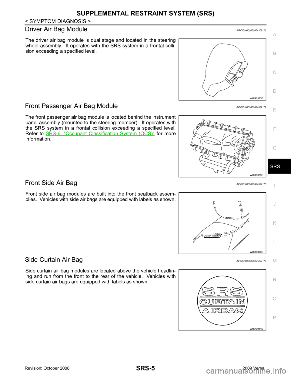
The driver air bag module is dual stage and located in the steering
wheel assembly. It operates with the SRS system in a frontal colli-
sion exceeding a specified level.
Front Passenger Air Bag Module INFOID:0000000004307177
The front passenger air bag module is located behind the instrument
panel assembly (mounted to the steering member). It operates with
the SRS system in a frontal collision exceeding a specified level.
Refer to SRS-6, " Occupant Classification System (OCS) " for more
information.
Front Side Air Bag INFOID:0000000004307178
Front side air bag modules are built into the front seatback assem-
blies. Vehicles with side air bags are equipped with labels as shown.
Side Curtain Air Bag INFOID:0000000004307179
Side curtain air bag modules are located above the vehicle headlin-
ing and run from the front to the rear of the vehicle. Vehicles with
side curtain air bags are equipped with labels as shown. WHIA0326E
WHIA0041E