2009 NISSAN LATIO steering wheel
[x] Cancel search: steering wheelPage 3254 of 4331

GI
SECTION GI
N
O P
CONTENTS
GENERAL INFORMATION
SERVICE INFORMATION .. ..........................2
PRECAUTIONS .............................................. .....2
Description .......................................................... ......2
Precaution for Supplemental Restraint System
(SRS) "AIR BAG" and "SEAT BELT PRE-TEN-
SIONER" ............................................................. ......
2
Precaution Necessary fo r Steering Wheel Rota-
tion After Battery Disconnect ............................... ......
2
General Precaution ............................................. ......3
Precaution for Three Way Catalyst ..................... ......4
Precaution for Fuel (Unleaded Regular Gasoline
Recommended) ................................................... ......
4
Precaution for Multiport Fuel Injection System or
Engine Control System ....................................... ......
5
Precaution for Hoses ........................................... ......5
Precaution for Engine Oils .................................. ......6
Precaution for Air Conditioning ........................... ......6
HOW TO USE THIS MANUAL ....................... .....7
Description .......................................................... ......7
Terms .................................................................. ......7
Units .................................................................... ......7
Contents .............................................................. ......7
Relation between Illustrations and Descriptions . ......8
Component .......................................................... ......8
How to Follow Trouble Diagnosis ........................ ......9
How to Read Wiring Diagr am ..................................13
Abbreviations ...................................................... ....20
SERVICE INFORMATION FOR ELECTRICAL
INCIDENT ....................................................... ....
22
How to Check Terminal ...........................................22 How to Perform Efficient Diagnosis for an Electri-
cal Incident .......................................................... ....
25
Control Units and Electrical Parts ........................ ....32
CONSULT-III CHECKING SYSTEM ................. 35
Description ........................................................... ....35
Function and System Application ........................ ....35
CONSULT-III Data Link Connector (DLC) Circuit ....36
LIFTING POINT ................................................. 38
Special Service Tool ............................................ ....38
Garage Jack and Safety Stand and 2-Pole Lift ... ....38
Board-On Lift ....................................................... ....39
TOW TRUCK TOWING ..................................... 40
Tow Truck Towing ............................................... ....40
Vehicle Recovery (Freeing a Stuck Vehicle) ....... ....40
TIGHTENING TORQUE OF STANDARD
BOLTS ............................................................... 41
Tightening Torque Table ..................................... ....41
RECOMMENDED CHEMICAL PRODUCTS
AND SEALANTS ............................................... 42
Recommended Chemical Product and Sealant ... ....42
IDENTIFICATION INFORMATION .................... 43
Model Variation .................................................... ....43
Dimensions .......................................................... ....46
Wheels & Tires .................................................... ....46
TERMINOLOGY ................................................ 47
SAE J1930 Terminology List ............................... ....47
Page 3256 of 4331

GI
N
O P
2. Use the Intelligent Key or mechanical key to turn the ignition switch to the
″ACC ″ position. At this time, the
steering lock will be released.
3. Disconnect both battery cables. The steering lock will remain released and the steering wheel can be
rotated.
4. Perform the necessary repair operation.
5. When the repair work is completed, return the ignition switch to the ″LOCK ″ position before connecting
the battery cables. (At this time, the steering lock mechanism will engage.)
6. Perform a self-diagnosis check of al l control units using CONSULT-III.
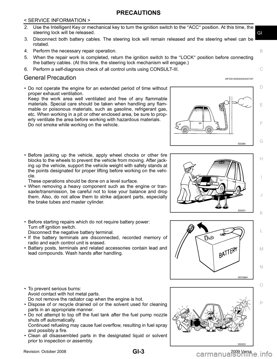
General Precaution INFOID:0000000004307347
• Do not operate the engine for an extended period of time without proper exhaust ventilation.
Keep the work area well ventilated and free of any flammable
materials. Special care should be taken when handling any flam-
mable or poisonous materials, such as gasoline, refrigerant gas,
etc. When working in a pit or ot her enclosed area, be sure to prop-
erly ventilate the area before working with hazardous materials.
Do not smoke while working on the vehicle.
• Before jacking up the vehicle, apply wheel chocks or other tire blocks to the wheels to prevent t he vehicle from moving. After jack-
ing up the vehicle, support the vehicle weight with safety stands at
the points designated for proper lifting before working on the vehi-
cle.
These operations should be done on a level surface.
• When removing a heavy component such as the engine or tran-
saxle/transmission, be careful not to lose your balance and drop
them. Also, do not allow them to strike adjacent parts, especially
the brake tubes and master cylinder.
• Before starting repairs which do not require battery power: Turn off ignition switch.
Disconnect the negative battery terminal.
• If the battery terminals are disconnected, recorded memory of
radio and each control unit is erased.
• Battery posts, terminals and related accessories contain lead and lead compounds. Wash hands after handling.
• To prevent serious burns: Avoid contact with hot metal parts.
Do not remove the radiator cap when the engine is hot.
• Dispose of or recycle drained oil or the solvent used for cleaning
parts in an appropriate manner.
• Do not attempt to top off the fuel tank after the fuel pump nozzle shuts off automatically.
Continued refueling may cause fuel overflow, resulting in fuel spray
and possibly a fire.
• Clean all disassembled parts in the designated liquid or solvent
prior to inspection or assembly. SGI231
SGI233
Page 3274 of 4331

GI
N
O P
FR, RR Front, Rear
LH, RH Left-Hand, Right-Hand M/T Manual Transaxle/TransmissionOD Overdrive
P/S Power Steering
SAE Society of Automotive Engineers, Inc.
SDS Service Data and Specifications SST Special Service Tools
2WD 2-Wheel Drive 22
2nd range 2nd gear
2 1
2nd range 1st gear
1 2
1st range 2nd gear
1 1
1st range 1st gear
ABBREVIATION DESCRIPTION
Page 3304 of 4331

GW
N
O P
CONTENTS
GLASSES, WINDOW SYSTEM & MIRRORS
SERVICE INFORMATION .. ..........................3
PRECAUTIONS .............................................. .....3
Precaution for Supplemental Restraint System
(SRS) "AIR BAG" and "SEAT BELT PRE-TEN-
SIONER" ............................................................. ......
3
Precaution Necessary fo r Steering Wheel Rota-
tion After Battery Disconnect ............................... ......
3
Precaution for Procedure without Cowl Top Cover ......4
Handling for Adhesive and Primer ...................... ......4
PREPARATION .............................................. .....5
Commercial Service Tool .................................... ......5
SQUEAK AND RATTLE TROUBLE DIAG-
NOSES ........................ ........................................6
Work Flow ........................................................... ......6
Generic Squeak and Rattle Troubleshooting ...... ......8
Diagnostic Worksheet ......................................... ....10
WINDSHIELD GLASS .................................... ....12
Removal and Installation .........................................12
OPERA WINDOW GLASS ............................. ....14
Removal and Installation .........................................14
REAR WINDOW GLASS AND MOLDING ..... ....16
Removal and Installation .........................................16
POWER WINDOW SYST EM ..............................19
Component Parts and Harness Connector Loca-
tion ...................................................................... ....
19
System Description ............................................. ....19
CAN Communication System Description ........... ....23
Schematic ........................................................... ....24
Wiring Diagram - WINDOW- ............................... ....25
Main Power Window and Door Lock/Unlock
Switch Harness Connector Terminal Layout ....... ....
29
Terminal and Reference Value for Main Power
Window and Door Lock/Unlock Switch ............... ....
29
Terminal and Reference Value for BCM ............. ....30
Work Flow ........................................................... ....30 CONSULT-III Function (B
CM) .................................30
Power Window Auto Operat ion Initialization ............31
Trouble Diagnosis Symptom Chart ...................... ....31
BCM Power Supply and Ground Circuit Inspection ....32
Main Power Window and Door Lock/Unlock
Switch Power Supply and Ground Circuit Inspec-
tion ....................................................................... ....
32
Front Power Window Motor LH Circuit Inspection ....33
Front Power Window RH Circuit Inspection (Pow-
er Window and Door Lock/Unlock Switch RH Op-
eration) ................................................................ ....
34
Front Power Window Motor RH Circuit Inspection ....34
Encoder Circuit Inspection ................................... ....36
Door Switch Check .............................................. ....38
Rear Power Window LH Circuit Inspection (Rear
Power Window Switch LH Operation) ................. ....
39
Rear Power Window RH Circu it Inspection (Rear
Power Window Switch RH Operation) ................. ....
40
Rear Power Window Motor LH Circuit Inspection ....40
Rear Power Window Motor RH Circuit Inspection ....42
FRONT DOOR GLASS AND REGULATOR ..... 44
Removal and Installation ..................................... ....44
Disassembly and Assembly ................................. ....46
Inspection after Installati on ......................................46
REAR DOOR GLASS AND REGULATOR ....... 48
Removal and Installation ..................................... ....48
Disassembly and Assembly ................................. ....50
Inspection after Installati on ......................................50
REAR WINDOW DEFOGGER .......................... 51
Component Parts and Harness Connector Loca-
tion ....................................................................... ....
51
System Description .............................................. ....51
CAN Communication System Description ........... ....52
Wiring Diagram - DEF - ....................................... ....53
Terminal and Reference Value for BCM ..................55
Terminal and Reference Va lue for IPDM E/R ..........55
Work Flow ............................................................ ....55
Page 3306 of 4331

GW
N
O P
SERVICE INFORMATION
PRECAUTIONS
Precaution for Supplemental Restraint System (SRS) "AIR BAG" and "SEAT BELT
PRE-TENSIONER" INFOID:0000000004306843
The Supplemental Restraint System such as “A IR BAG” and “SEAT BELT PRE-TENSIONER”, used along
with a front seat belt, helps to reduce the risk or severi ty of injury to the driver and front passenger for certain
types of collision. This system includes seat belt switch inputs and dual stage front air bag modules. The SRS
system uses the seat belt switches to determine the front air bag deployment, and may only deploy one front
air bag, depending on the severity of a collision and w hether the front occupants are belted or unbelted.
Information necessary to service the system safely is included in the SRS and SB section of this Service Man-
ual.
WARNING:
• To avoid rendering the SRS inoper ative, which could increase the risk of personal injury or death in
the event of a collision which would result in air bag inflation, all maintenance must be performed by
an authorized NISSAN/INFINITI dealer.
• Improper maintenance, including in correct removal and installation of the SRS, can lead to personal
injury caused by unintentional act ivation of the system. For removal of Spiral Cable and Air Bag
Module, see the SRS section.
• Do not use electrical test equipm ent on any circuit related to the SRS unless instructed to in this
Service Manual. SRS wiring harnesses can be identi fied by yellow and/or orange harnesses or har-
ness connectors.
Precaution Necessary for Steering Wh eel Rotation After Battery Disconnect
INFOID:0000000004687763
NOTE:
• This Procedure is applied only to models with Inte lligent Key system and NATS (NISSAN ANTI-THEFT SYS-
TEM).
• Remove and install all control units after disconnecti ng both battery cables with the ignition knob in the
″ LOCK ″ position.
• Always use CONSULT-III to perform self-diagnosis as a part of each function inspection after finishing work.
If DTC is detected, perform trouble diagnosis according to self-diagnostic results.
For models equipped with the Intelligent Key system and NATS , an electrically controlled steering lock mech-
anism is adopted on the key cylinder.
For this reason, if the battery is disconnected or if the battery is discharged, the steering wheel will lock and
steering wheel rotation will become impossible.
If steering wheel rotation is required when battery pow er is interrupted, follow the procedure below before
starting the repair operation.
OPERATION PROCEDURE 1. Connect both battery cables. NOTE:
Supply power using jumper cables if battery is discharged.
2. Use the Intelligent Key or mechanical key to turn the ignition switch to the ″ACC ″ position. At this time, the
steering lock will be released.
3. Disconnect both battery cables. The steering lock will remain released and the steering wheel can be
rotated.
4. Perform the necessary repair operation.
5. When the repair work is completed, return the ignition switch to the ″LOCK ″ position before connecting
the battery cables. (At this time, the steering lock mechanism will engage.)
6. Perform a self-diagnosis check of al l control units using CONSULT-III.
Page 3371 of 4331

IP
N
O P
CONTENTS
INSTRUMENT PANEL
PRECAUTION ....... ........................................2
PRECAUTIONS .............................................. .....2
Precaution for Supplemental Restraint System
(SRS) "AIR BAG" and "SEAT BELT PRE-TEN-
SIONER" ............................................................. ......
2
Precaution Necessary fo r Steering Wheel Rota-
tion After Battery Disconnect ............................... ......
2
Precaution ........................................................... ......2
PREPARATION .... ........................................4
PREPARATION .............................................. .....4
Special Service Tool ........................................... ......4
Commercial Service Tool .................................... ......4 SYMPTOM DIAGNOSIS ....
...........................5
SQUEAK AND RATTLE TROUBLE DIAG-
NOSES ............................................................... 5
Work Flow ............................................................ .....5
Generic Squeak and Rattle Troubleshooting ....... .....7
Diagnostic Worksheet .......................................... .....9
ON-VEHICLE REPAIR ..... ............................11
INSTRUMENT PANEL ASSEMBLY ................. 11
Component Parts ................................................. ....11
Removal and Installation ..................................... ....12
Disassembly and Assembly ................................. ....23
Page 3607 of 4331

LT
N
O P
CONTENTS
LIGHTING SYSTEM
SERVICE INFORMATION .. ..........................3
PRECAUTIONS .............................................. .....3
Precaution for Supplemental Restraint System
(SRS) "AIR BAG" and "SEAT BELT PRE-TEN-
SIONER" ............................................................. ......
3
Precaution Necessary fo r Steering Wheel Rota-
tion After Battery Disconnect ............................... ......
3
HEADLAMP (FOR USA) ................................ .....4
Component Parts and Harness Connector Loca-
tion ...................................................................... ......
4
System Description ............................................. ......4
CAN COMMUNICATION SYSTEM DESCRIP-
TION .................................................................... ......
5
Schematic ........................................................... ......6
Wiring Diagram ................................................... ......7
Terminal and Reference Value for BCM ............. ....10
Terminal and Reference Value for IPDM E/R ..... ....10
How to Perform Trouble Diagnosis ..................... ....11
Preliminary Check ............................................... ....11
CONSULT-III Function (BCM) ............................. ....11
CONSULT-III Function (IPDM E/R) ..................... ....12
Headlamp High Beam Does Not Illuminate (Both
Sides) .................................................................. ....
13
Headlamp High Beam Does Not Illuminate (One
Side) .................................................................... ....
15
High Beam Indicator Lamp Does Not Illuminate .....16
Headlamp Low Beam Does Not Illuminate (Both
Sides) .................................................................. ....
16
Headlamp Low Beam Does Not Illuminate (One
Side) .................................................................... ....
19
Headlamps Do Not Turn OFF ............................. ....20
Aiming Adjustment .............................................. ....21
Bulb Replacement ........ ...........................................22
Removal and Installation .........................................23
Disassembly and Assembly ................................ ....23
HEADLAMP (FOR CANADA) - DAYTIME
LIGHT SYSTEM - ........................................... ....25 Component Parts and Harness Connector Loca-
tion ....................................................................... ....
25
Page 3609 of 4331

LT
N
O P
SERVICE INFORMATION
PRECAUTIONS
Precaution for Supplemental Restraint System (SRS) "AIR BAG" and "SEAT BELT
PRE-TENSIONER" INFOID:0000000004306519
The Supplemental Restraint System such as “A IR BAG” and “SEAT BELT PRE-TENSIONER”, used along
with a front seat belt, helps to reduce the risk or severi ty of injury to the driver and front passenger for certain
types of collision. This system includes seat belt switch inputs and dual stage front air bag modules. The SRS
system uses the seat belt switches to determine the front air bag deployment, and may only deploy one front
air bag, depending on the severity of a collision and w hether the front occupants are belted or unbelted.
Information necessary to service the system safely is included in the SRS and SB section of this Service Man-
ual.
WARNING:
• To avoid rendering the SRS inoper ative, which could increase the risk of personal injury or death in
the event of a collision which would result in air bag inflation, all maintenance must be performed by
an authorized NISSAN/INFINITI dealer.
• Improper maintenance, including in correct removal and installation of the SRS, can lead to personal
injury caused by unintentional act ivation of the system. For removal of Spiral Cable and Air Bag
Module, see the SRS section.
• Do not use electrical test equipm ent on any circuit related to the SRS unless instructed to in this
Service Manual. SRS wiring harnesses can be identi fied by yellow and/or orange harnesses or har-
ness connectors.
Precaution Necessary for Steering Wh eel Rotation After Battery Disconnect
INFOID:0000000004683900
NOTE:
• This Procedure is applied only to models with Inte lligent Key system and NATS (NISSAN ANTI-THEFT SYS-
TEM).
• Remove and install all control units after disconnecti ng both battery cables with the ignition knob in the
″ LOCK ″ position.
• Always use CONSULT-III to perform self-diagnosis as a part of each function inspection after finishing work.
If DTC is detected, perform trouble diagnosis according to self-diagnostic results.
For models equipped with the Intelligent Key system and NATS , an electrically controlled steering lock mech-
anism is adopted on the key cylinder.
For this reason, if the battery is disconnected or if the battery is discharged, the steering wheel will lock and
steering wheel rotation will become impossible.
If steering wheel rotation is required when battery pow er is interrupted, follow the procedure below before
starting the repair operation.
OPERATION PROCEDURE 1. Connect both battery cables. NOTE:
Supply power using jumper cables if battery is discharged.
2. Use the Intelligent Key or mechanical key to turn the ignition switch to the ″ACC ″ position. At this time, the
steering lock will be released.
3. Disconnect both battery cables. The steering lock will remain released and the steering wheel can be
rotated.
4. Perform the necessary repair operation.
5. When the repair work is completed, return the ignition switch to the ″LOCK ″ position before connecting
the battery cables. (At this time, the steering lock mechanism will engage.)
6. Perform a self-diagnosis check of al l control units using CONSULT-III.