Page 2758 of 4171

MWI-36
< COMPONENT DIAGNOSIS >
PARKING BRAKE SWITCH SIGNAL CIRCUIT
PARKING BRAKE SWITCH SIGNAL CIRCUIT
DescriptionINFOID:0000000003776644
Transmits the parking brake switch signal to the combination meter.
Component Function CheckINFOID:0000000003776645
1.COMBINATION METER INPUT SIGNAL
1. Start engine.
2. Monitor “BRAKE” warning lamp while applying and releasing the parking brake.
>> Inspection End.
Diagnosis ProcedureINFOID:0000000003776646
1.CHECK PARKING BRAKE SWITCH CIRCUIT
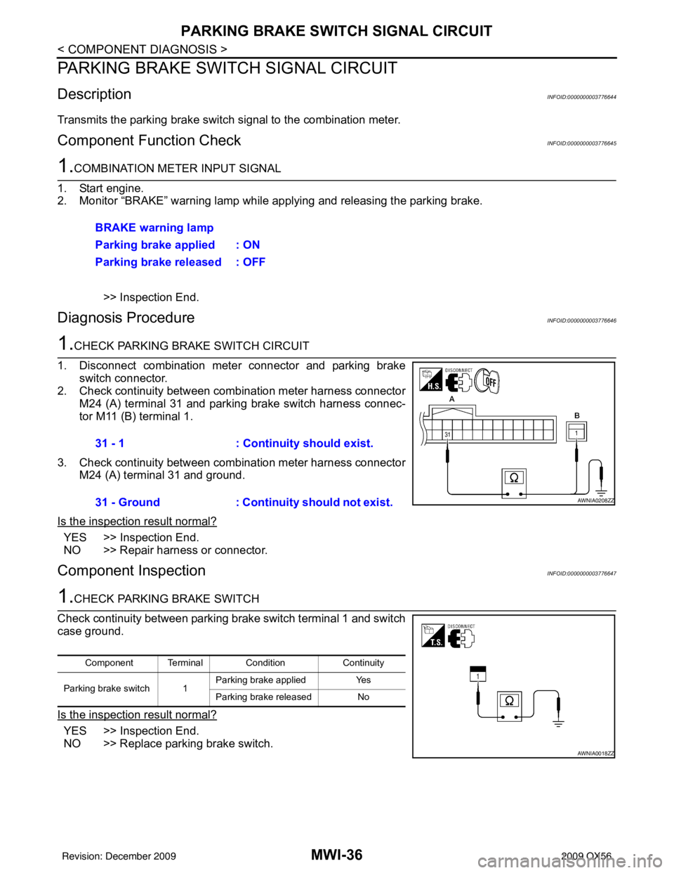
1. Disconnect combination meter connector and parking brake switch connector.
2. Check continuity between combination meter harness connector M24 (A) terminal 31 and parking brake switch harness connec-
tor M11 (B) terminal 1.
3. Check continuity between combination meter harness connector M24 (A) terminal 31 and ground.
Is the inspection result normal?
YES >> Inspection End.
NO >> Repair harness or connector.
Component InspectionINFOID:0000000003776647
1.CHECK PARKING BRAKE SWITCH
Check continuity between parking brake switch terminal 1 and switch
case ground.
Is the inspection result normal?
YES >> Inspection End.
NO >> Replace parking brake switch. BRAKE warning lamp
Parking brake applied : ON
Parking brake released : OFF
31 - 1
: Continuity should exist.
31 - Ground : Continuity should not exist.
AWNIA0208ZZ
Component Terminal Condition Continuity
Parking brake switch 1 Parking brake applied
Yes
Parking brake released No
AWNIA0018ZZ
Revision: December 20092009 QX56
Page 2764 of 4171

MWI-42
< ECU DIAGNOSIS >
COMBINATION METER
ECU DIAGNOSIS
COMBINATION METER
Reference ValueINFOID:0000000003776653
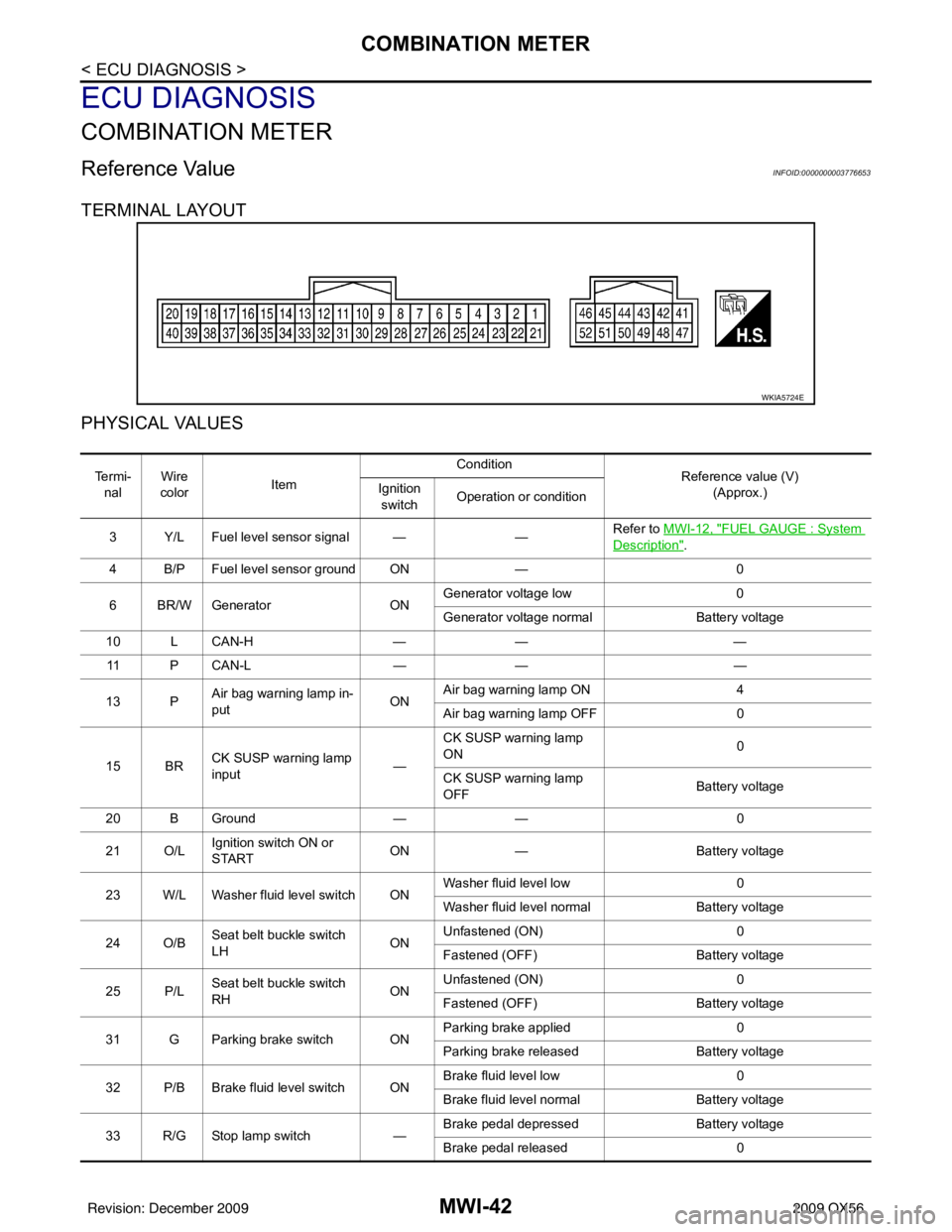
TERMINAL LAYOUT
PHYSICAL VALUES
WKIA5724E
Te r m i -nal Wire
color Item Condition
Reference value (V)
(Approx.)
Ignition
switch Operation or condition
3 Y/L Fuel level sensor signal — —Refer to MWI-12, "
FUEL GAUGE : System
Description".
4 B/P Fuel level sensor ground ON —0
6 BR/W Generator ONGenerator voltage low
0
Generator voltage normal Battery voltage
10 L CAN-H —— —
11 P C A N - L —— —
13 P Air bag warning lamp in-
put ONAir bag warning lamp ON
4
Air bag warning lamp OFF 0
15 BR CK SUSP warning lamp
input —CK SUSP warning lamp
ON
0
CK SUSP warning lamp
OFF Battery voltage
20 B Ground —— 0
21 O/L Ignition switch ON or
START ON
— Battery voltage
23 W/L Washer fluid level switch ON Washer fluid level low
0
Washer fluid level normal Battery voltage
24 O/B Seat belt buckle switch
LH ONUnfastened (ON)
0
Fastened (OFF) Battery voltage
25 P/L Seat belt buckle switch
RH ONUnfastened (ON)
0
Fastened (OFF) Battery voltage
31 G Parking brake switch ON Parking brake applied
0
Parking brake released Battery voltage
32 P/B Brake fluid level switch ON Brake fluid level low
0
Brake fluid level normal Battery voltage
33 R/G Stop lamp switch —Brake pedal depressed
Battery voltage
Brake pedal released 0
Revision: December 20092009 QX56
Page 2818 of 4171

MWI-96
< SYMPTOM DIAGNOSIS >
THE PARKING BRAKE RELEASE WARNING CONTINUES DISPLAYING, OR DOES NOT DISPLAY
THE PARKING BRAKE RELEASE WARNING CONTINUES DISPLAYING,
OR DOES NOT DISPLAY
DescriptionINFOID:0000000003776677
• The parking brake warning is displayed while drivi ng the vehicle even though the parking brake is released.
• The parking brake warning is not displayed even though driving the vehicle with the parking brake applied.
Diagnosis ProcedureINFOID:0000000003776678
1.CHECK PARKING BRAKE WARNING LAMP OPERATION
1. Start engine.
2. Monitor “BRAKE” warning lamp while applying and releasing the parking brake.
Is the inspection result normal?
YES >> Replace combination meter. Refer to MWI-102, "Removal and Installation".
NO >> GO TO 2
2.CHECK PARKING BRAKE SWITCH SIGNAL CIRCUIT
1. Turn ignition switch OFF.
2. Check the parking brake switch signal circuit. Refer to MWI-36, "
Diagnosis Procedure".
Is the inspection result normal?
YES >> GO TO 3
NG >> Repair harness or connector.
3.CHECK PARKING BRAKE SWITCH UNIT
Perform a unit check for the parking brake switch. Refer to MWI-36, "
Component Inspection".
Is the inspection result normal?
YES >> Replace combination meter. Refer to MWI-102, "Removal and Installation".
NO >> Replace parking brake switch. BRAKE warning lamp
Parking brake applied : ON
Parking brake released : OFF
Revision: December 20092009 QX56
Page 2826 of 4171

PB-1
BRAKES
C
DE
G H
I
J
K L
M
SECTION PB
A
B
PB
N
O P
CONTENTS
PARKING BRAKE SYSTEM
PRECAUTION ....... ........................................2
PRECAUTIONS .............................................. .....2
Precaution for Supplemental Restraint System
(SRS) "AIR BAG" and "SEAT BELT PRE-TEN-
SIONER" ............................................................. ......
2
Precaution Necessary for Steering Wheel Rota-
tion After Battery Disconnect ............................... ......
2
PREPARATION ............................................4
PREPARATION .............................................. .....4
Commercial Service Tool .................................... ......4
ON-VEHICLE MAINTENANCE .....................5
PARKING BRAKE SYSTEM .......................... .....5
On-Vehicle Service ............................................. ......5
ON-VEHICLE REPAIR ..................................7
PARKING BRAKE CONTROL ...........................7
Component .......................................................... .....7
Removal and Installation ..........................................7
PARKING BRAKE SHOE ..................................9
Removal and Installation ..........................................9
SERVICE DATA AND SPECIFICATIONS
(SDS) ............... .......................................... ...
12
SERVICE DATA AND SPECIFICATIONS
(SDS) .................................................................
12
Parking Brake ...................................................... ....12
Parking Brake Control .............................................12
Revision: December 20092009 QX56
Page 2829 of 4171
PB-4
< PREPARATION >
PREPARATION
PREPARATION
PREPARATION
Commercial Service ToolINFOID:0000000003772469
The actual shapes of Kent-Moore tools may differ from those of special service tools illustrated here.
(Kent-Moore No.)
Tool name Description
(J-21177-A)
Brake drum clearance gauge Measuring rear rotor drum to parking
brake shoe clearance
Power tool Loosening bolts and nuts
WFIA0167E
PBIC0190E
Revision: December 20092009 QX56
Page 2830 of 4171

PARKING BRAKE SYSTEMPB-5
< ON-VEHICLE MAINTENANCE >
C
DE
G H
I
J
K L
M A
B
PB
N
O P
ON-VEHICLE MAINTENANCE
PARKING BRAKE SYSTEM
On-Vehicle ServiceINFOID:0000000003772470
PEDAL STROKE
• When parking brake pedal is operated with the specified forc e, make sure the stroke is within the specified
number of notches. Check by listening and counting the ratchet clicks.
INSPECTION
• Make sure the components are attached pr operly, checking for looseness or backlash.
• Check parking brake pedal assembly for bends, damage and cracks, and replace if necessary.
• Check cable for wear and damage, and replace if necessary.
• Check parking brake warning lamp switch for malfunction, and replace if necessary. Refer to BCS-36, "
Diag-
nosis Procedure".
ADJUSTMENT
1. Remove the lower instrument panel LH. Refer to IP-15, "Exploded View".
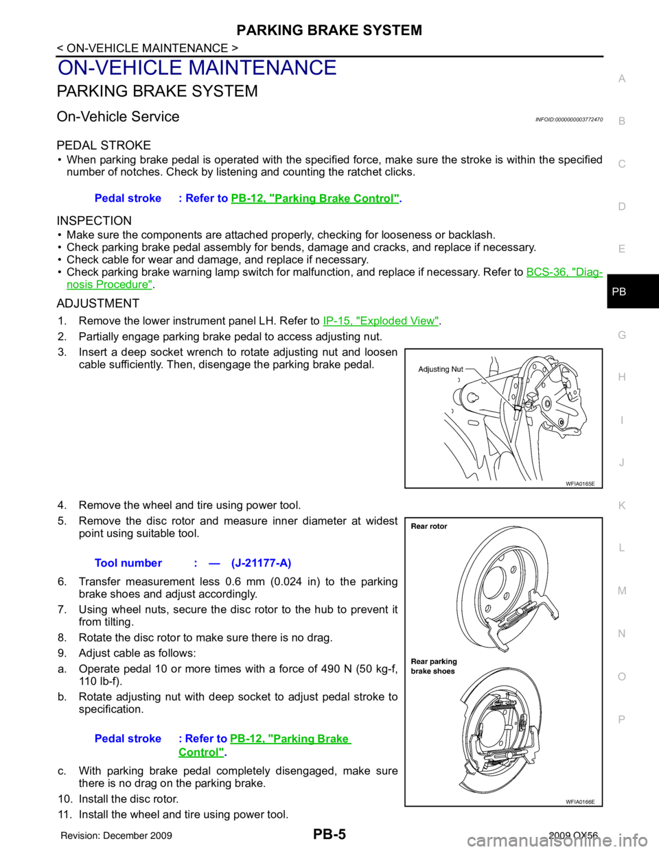
2. Partially engage parking brake pedal to access adjusting nut.
3. Insert a deep socket wrench to rotate adjusting nut and loosen cable sufficiently. Then, disengage the parking brake pedal.
4. Remove the wheel and tire using power tool.
5. Remove the disc rotor and measure inner diameter at widest point using suitable tool.
6. Transfer measurement less 0.6 mm (0.024 in) to the parking brake shoes and adjust accordingly.
7. Using wheel nuts, secure the disc rotor to the hub to prevent it from tilting.
8. Rotate the disc rotor to make sure there is no drag.
9. Adjust cable as follows:
a. Operate pedal 10 or more times with a force of 490 N (50 kg-f, 110 lb-f).
b. Rotate adjusting nut with deep socket to adjust pedal stroke to specification.
c. With parking brake pedal completely disengaged, make sure there is no drag on the parking brake.
10. Install the disc rotor.
11. Install the wheel and tire using power tool. Pedal stroke : Refer to
PB-12, "
Parking Brake Control".
WFIA0165E
Tool number : — (J-21177-A)
Pedal stroke : Refer to PB-12, "
Parking Brake
Control".
WFIA0166E
Revision: December 20092009 QX56
Page 2831 of 4171
PB-6
< ON-VEHICLE MAINTENANCE >
PARKING BRAKE SYSTEM
12. Install the lower instrument panel LH. Refer to IP-15, "Exploded View".
Revision: December 20092009 QX56
Page 2832 of 4171
PARKING BRAKE CONTROLPB-7
< ON-VEHICLE REPAIR >
C
DE
G H
I
J
K L
M A
B
PB
N
O P
ON-VEHICLE REPAIR
PARKING BRAKE CONTROL
ComponentINFOID:0000000003772471
Removal and InstallationINFOID:0000000003772472
REMOVAL
1. Remove lower instrument panel LH. Refer to IP-17, "Removal and Installation".
2. Remove center console. Refer to IP-20, "
Removal and Installation".
3. Remove floor trim. Refer to INT-16, "
Removal and Installation".
4. Remove adjusting nut and discard. CAUTION:
Do not reuse adjusting nut after removing it.
5. Remove the lock plate from the front cable.
6. Remove front cable retaining bolts and nut.
7. Disconnect return spring from equalizer.
8. Disconnect right and left rear cables from equalizer.
9. Remove rear wheel hub. Refer to RAX-7, "
Removal and Installa-
tion".
1. Pedal assembly 2. Front cable3. Right rear cable
4. Left rear cable 5. Return spring6. Equalizer
7. Adjusting nut 8. Lock plate
WFIA0218E
WFIA0165E
Revision: December 20092009 QX56