2009 INFINITI QX56 fuel tank removal
[x] Cancel search: fuel tank removalPage 1579 of 4171
![INFINITI QX56 2009 Factory Service Manual
EC-252
< COMPONENT DIAGNOSIS >[VK56DE]
P0455 EVAP CONTROL SYSTEM
2. Check for genuine NISSAN fuel filler cap design.
OK or NG
OK >> GO TO 2.
NG >> Replace with genuine NISSAN fuel filler cap.
2.CHECK INFINITI QX56 2009 Factory Service Manual
EC-252
< COMPONENT DIAGNOSIS >[VK56DE]
P0455 EVAP CONTROL SYSTEM
2. Check for genuine NISSAN fuel filler cap design.
OK or NG
OK >> GO TO 2.
NG >> Replace with genuine NISSAN fuel filler cap.
2.CHECK](/manual-img/42/57031/w960_57031-1578.png)
EC-252
< COMPONENT DIAGNOSIS >[VK56DE]
P0455 EVAP CONTROL SYSTEM
2. Check for genuine NISSAN fuel filler cap design.
OK or NG
OK >> GO TO 2.
NG >> Replace with genuine NISSAN fuel filler cap.
2.CHECK FUEL FILLER CAP INSTALLATION
Check that the cap is tightened proper ly by rotating the cap clockwise.
OK or NG
OK >> GO TO 3.
NG >> 1. Open fuel filler cap, then clean cap and fuel filler neck threads using air blower.
2. Retighten until ratcheting sound is heard.
3.CHECK FUEL FILLER CAP FUNCTION
Check for air releasing sound while opening the fuel filler cap.
OK or NG
OK >> GO TO 5.
NG >> GO TO 4.
4.CHECK FUEL TANK VACUUM RELIEF VALVE
Refer to EC-264, "Component Inspection"
.
OK or NG
OK >> GO TO 5.
NG >> Replace fuel filler cap with a genuine one.
5.CHECK EVAP PURGE LINE
Check EVAP purge line (pipe, rubber tube, fuel tank and EVAP canister) for cracks, improper connection or
disconnection.
Refer to EC-37, "Description"
.
OK or NG
OK >> GO TO 6.
NG >> Repair or reconnect the hose.
6.CLEAN EVAP PURGE LINE
Clean EVAP purge line (pipe and rubber tube) using air blower.
>> GO TO 7.
7.CHECK EVAP CANISTER VENT CONTROL VALVE
Check the following.
EVAP canister vent control valve is installed properly. Refer to EC-491, "Removal and Installation"
.
EVAP canister vent control valve. Refer to EC-232, "Component Inspection"
.
OK or NG
OK >> GO TO 8.
NG >> Repair or replace EVAP cani ster vent control valve and O-ring.
8.INSTALL THE PRESSURE PUMP
SEF915U
Revision: December 20092009 QX56
Page 1594 of 4171
![INFINITI QX56 2009 Factory Service Manual
P0461 FUEL LEVEL SENSOREC-267
< COMPONENT DIAGNOSIS > [VK56DE]
C
D
E
F
G H
I
J
K L
M A
EC
NP
O
P0461 FUEL LEVEL SENSOR
Component DescriptionINFOID:0000000003771533
The fuel level sensor is mounted in INFINITI QX56 2009 Factory Service Manual
P0461 FUEL LEVEL SENSOREC-267
< COMPONENT DIAGNOSIS > [VK56DE]
C
D
E
F
G H
I
J
K L
M A
EC
NP
O
P0461 FUEL LEVEL SENSOR
Component DescriptionINFOID:0000000003771533
The fuel level sensor is mounted in](/manual-img/42/57031/w960_57031-1593.png)
P0461 FUEL LEVEL SENSOREC-267
< COMPONENT DIAGNOSIS > [VK56DE]
C
D
E
F
G H
I
J
K L
M A
EC
NP
O
P0461 FUEL LEVEL SENSOR
Component DescriptionINFOID:0000000003771533
The fuel level sensor is mounted in the fuel level sensor unit. The
sensor detects a fuel level in the fuel tank and transmits a signal to
the combination meter. The combination meter sends the fuel level
sensor signal to the ECM through CAN communication line.
It consists of two parts, one is mechanical float and the other is vari-
able resistor. Fuel level sensor output voltage changes depending on
the movement of the fuel mechanical float.
On Board Diagnosis LogicINFOID:0000000003771534
NOTE:
If DTC P0461 is displayed with DTC U1000 or U1001, first perform the trouble diagnosis for DTC
U1000, U1001. Refer to EC-86
.
If DTC P0461 is displayed with DT C P0607, first perform the trouble diagnosis for DTC P0607. Refer
to EC-284
.
Driving long distances naturally affect fuel gauge level.
This diagnosis detects the fuel gauge malfunction of the gauge not moving even after a long distance has
been driven.
Overall Function CheckINFOID:0000000003771535
Use this procedure to check the overall function of the f uel level sensor function. During this check, a 1st trip
DTC might not be confirmed.
WARNING:
When performing following procedure, be sure to observe the handling of the fuel. Refer to FL-11,
"Removal and Installation".
TESTING CONDITION:
Before starting overall function check, preparation of draining fuel and refilling fuel is required.
WITH CONSULT-III
NOTE:
Start from step 10, if it is possible to confirm that the fuel cannot be drained by 30 (7-7/8 US gal, 6-5/
8 Imp gal) in advance.
1. Prepare a fuel container and a spare hose.
2. Release fuel pressure from fuel line, refer to EC-487, "Fuel Pressure Check"
.
3. Remove the fuel feed hose on the fuel level sensor unit.
4. Connect a spare fuel hose where the fuel feed hose was removed.
5. Turn ignition switch OFF and wait at least 10 seconds then turn ON.
6. Select “FUEL LEVEL SE” in “DAT A MONITOR” mode with CONSULT-III.
7. Check “FUEL LEVEL SE” output voltage and note it.
8. Select “FUEL PUMP” in “ACT IVE TEST” mode with CONSULT-III.
9. Touch “ON” and drain fuel approximately 30 (7-7/8 US gal, 6-5/8 Imp gal) and stop it.
10. Check “FUEL LEVEL SE” output voltage and note it.
11. Fill fuel into the fuel tank for 30 (7-7/8 US gal, 6-5/8 Imp gal).
BBIA0402E
DTC No. Trouble diagnosis name DTC detecting condition Possible cause
P0461
0461 Fuel level sensor circuit
range/performance The output signal of the fuel level sensor does
not change within the specified range even
though the vehicle has been driven a long dis-
tance. Harness or connectors
(The CAN communication line is open or
shorted)
Harness or connectors
(The sensor circuit is open or shorted)
Combination meter
Fuel level sensor
Revision: December 20092009 QX56
Page 2154 of 4171
FL-1
ENGINE
C
DE
F
G H
I
J
K L
M
SECTION FL
A
FL
N
O P
CONTENTS
FUEL SYSTEM
PRECAUTION ....... ........................................2
PRECAUTIONS .............................................. .....2
Precaution for Supplemental Restraint System
(SRS) "AIR BAG" and "SEAT BELT PRE-TEN-
SIONER" ............................................................. ......
2
Precaution Necessary for Steering Wheel Rota-
tion After Battery Disconnect ............................... ......
2
FUEL SYSTEM ....................................................4
General Precaution ............................................. ......4
PREPARATION ............................................5
PREPARATION .............................................. .....5
Special Service Tool ........................................... ......5
Commercial Service Tool ..........................................5
BASIC INSPECTION ....................................6
FUEL SYSTEM ............................................... .....6
Checking Fuel Line ............................................. ......6
REMOVAL AND INSTALLATION ................7
FUEL LEVEL SENSOR UNIT, FUEL FILTER
AND FUEL PUMP ASSEMBLY .........................
7
Removal and Installation ..................................... .....7
FUEL TANK ......................................................11
Removal and Installation ..................................... ....11
DISASSEMBLY AND ASSEMBLY ..............16
FUEL LEVEL SENSOR UNIT, FUEL FILTER
AND FUEL PUMP ASSEMBLY ........................
16
Disassembly and Assembly ................................. ....16
SERVICE DATA AND SPECIFICATIONS
(SDS) ............... .......................................... ...
17
SERVICE DATA AND SPECIFICATIONS
(SDS) .................................................................
17
Standard and Limit .............................................. ....17
Revision: December 20092009 QX56
Page 2160 of 4171
FUEL LEVEL SENSOR UNIT, FUEL FILTER AND FUEL PUMP ASSEMBLYFL-7
< REMOVAL AND INSTALLATION >
C
DE
F
G H
I
J
K L
M A
FL
NP
O
REMOVAL AND INSTALLATION
FUEL LEVEL SENSOR UNIT, FUEL FI
LTER AND FUEL PUMP ASSEMBLY
Removal and InstallationINFOID:0000000003771773
REMOVAL
WARNING:
Follow the “General Precautions” before working on the fuel system. Refer to FL-4, "
General Precau-
tion".
1. Remove the fuel filler cap to release the pressure from inside the fuel tank.
2. Release the fuel pressure from the fuel lines. Refer to EC-487, "
Fuel Pressure Check".
3. Remove the second row seat and the third row LH seat. Refer to SE-55, "
Removal and Installation" (sec-
ond row), SE-58, "
LH Side Seat" (third row).
4. Disconnect the battery negative terminal. Refer to PG-76, "
Removal and Installation".
5. Remove the second and third row rear seat belt buckles mounted on the floor. Refer to SB-7, "
Removal
and Installation of Second Row Seat Belt", SB-9, "Removal and Installation of Third Row Seat Belt".
6. Remove the LH center pillar trim, the LH rear trim panel, and the LH rear side door kick plate and weather stripping. Refer to INT-14, "
Removal and Installation".
7. Remove the second row rear center console and base, if equipped. Refer to IP-21, "
Removal and Installa-
tion".
8. Reposition the floor carpet out of the way to access the inspection hole cover, located under the center LH rear seat.
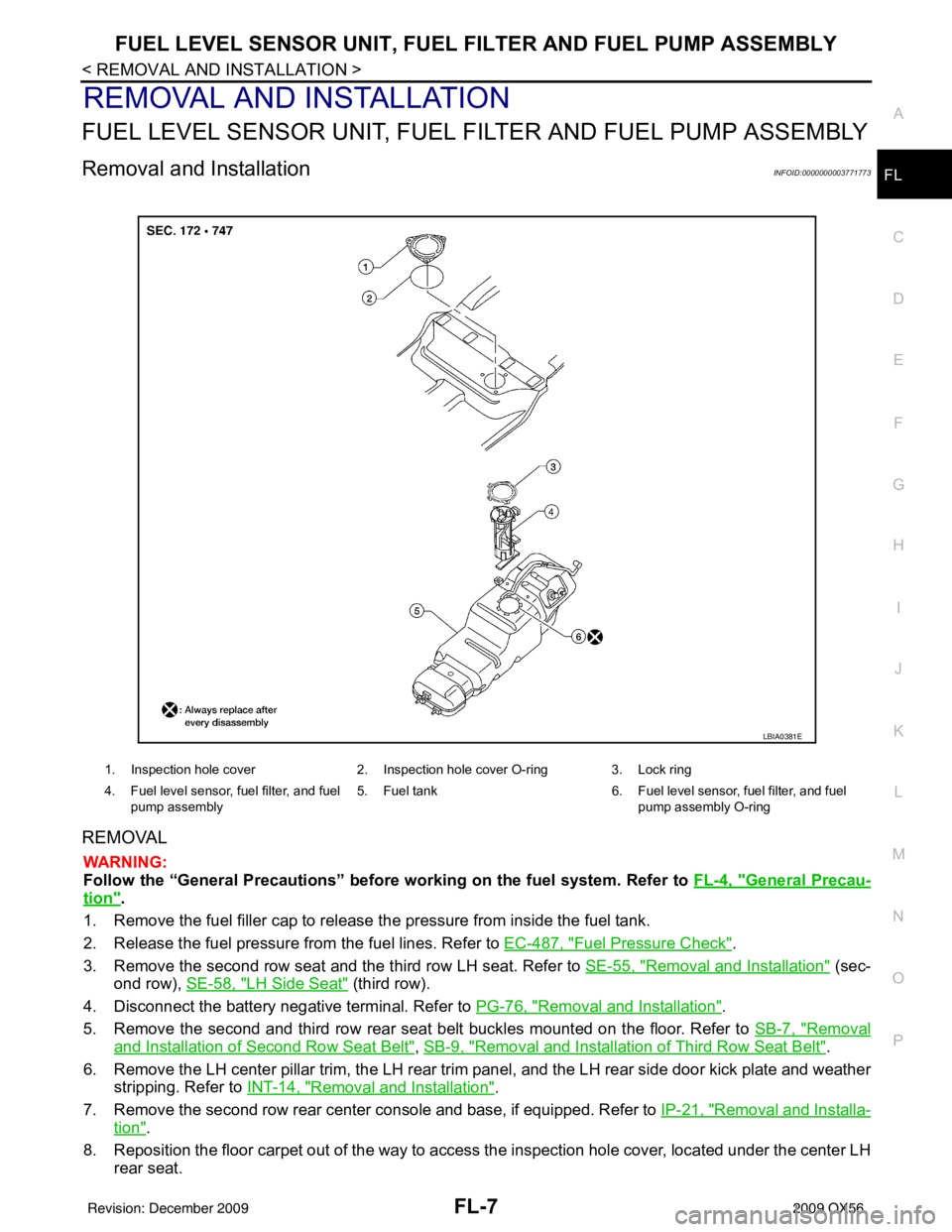
1. Inspection hole cover 2. Inspection hole cover O-ring 3. Lock ring
4. Fuel level sensor, fuel filter, and fuel pump assembly 5. Fuel tank
6. Fuel level sensor, fuel filter, and fuel
pump assembly O-ring
LBIA0381E
Revision: December 20092009 QX56
Page 2164 of 4171
FUEL TANKFL-11
< REMOVAL AND INSTALLATION >
C
DE
F
G H
I
J
K L
M A
FL
NP
O
FUEL TANK
Removal and InstallationINFOID:0000000003771774
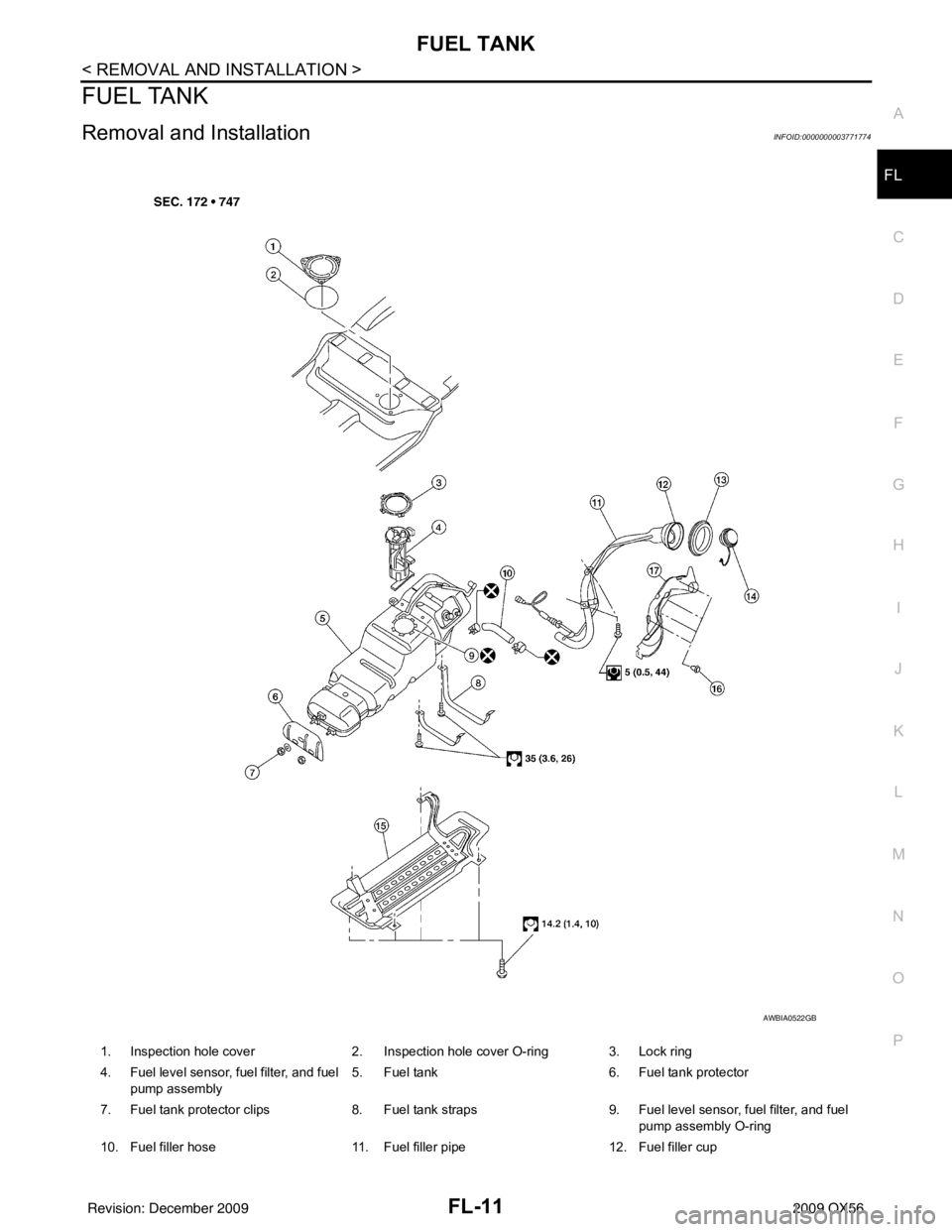
1. Inspection hole cover
2. Inspection hole cover O-ring 3. Lock ring
4. Fuel level sensor, fuel filter, and fuel pump assembly 5. Fuel tank
6. Fuel tank protector
7. Fuel tank protector clips 8. Fuel tank straps 9. Fuel level sensor, fuel filter, and fuel
pump assembly O-ring
10. Fuel filler hose 11. Fuel filler pipe 12. Fuel filler cup
AWBIA0522GB
Revision: December 20092009 QX56
Page 2165 of 4171
FL-12
< REMOVAL AND INSTALLATION >
FUEL TANK
REMOVAL
WARNING:
Follow the “General Precautions” before working on the fuel system. Refer to FL-4, "
General Precau-
tion".
1. Remove the fuel filler cap to release the pressure from inside the fuel tank.
2. Release the fuel pressure from the fuel lines. Refer to EC-487, "
Fuel Pressure Check".
3. Drain the fuel from the fuel tank, if necessary.
a. Position the vehicle so it is level.
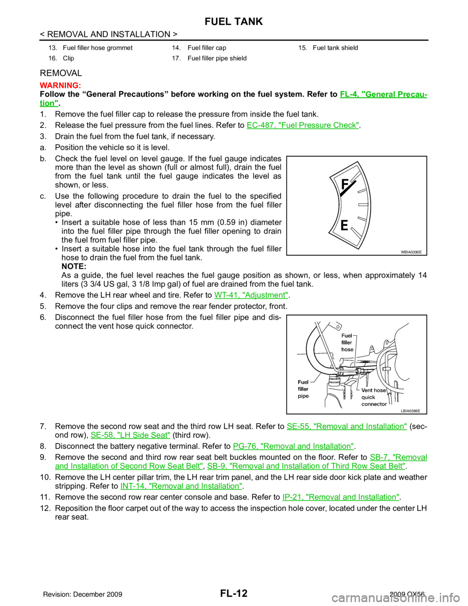
b. Check the fuel level on level gauge. If the fuel gauge indicates more than the level as shown (full or almost full), drain the fuel
from the fuel tank until the fuel gauge indicates the level as
shown, or less.
c. Use the following procedure to drain the fuel to the specified level after disconnecting the fuel filler hose from the fuel filler
pipe.
• Insert a suitable hose of less than 15 mm (0.59 in) diameterinto the fuel filler pipe through the fuel filler opening to drain
the fuel from fuel filler pipe.
• Insert a suitable hose into the fuel tank through the fuel filler hose to drain the fuel from the fuel tank.
NOTE:
As a guide, the fuel level reaches the fuel gauge position as shown, or less, when approximately 14
liters (3 3/4 US gal, 3 1/8 Imp gal) of fuel are drained from the fuel tank.
4. Remove the LH rear wheel and tire. Refer to WT-41, "
Adjustment".
5. Remove the four clips and remove the rear fender protector, front.
6. Disconnect the fuel filler hose from the fuel filler pipe and dis- connect the vent hose quick connector.
7. Remove the second row seat and the third row LH seat. Refer to SE-55, "
Removal and Installation" (sec-
ond row), SE-58, "
LH Side Seat" (third row).
8. Disconnect the battery negative terminal. Refer to PG-76, "
Removal and Installation".
9. Remove the second and third row rear seat belt buckles mounted on the floor. Refer to SB-7, "
Removal
and Installation of Second Row Seat Belt", SB-9, "Removal and Installation of Third Row Seat Belt".
10. Remove the LH center pillar trim, the LH rear trim panel, and the LH rear side door kick plate and weather
stripping. Refer to INT-14, "
Removal and Installation".
11. Remove the second row rear center console and base. Refer to IP-21, "
Removal and Installation".
12. Reposition the floor carpet out of the way to access the inspection hole cover, located under the center LH
rear seat.
13. Fuel filler hose grommet 14. Fuel filler cap 15. Fuel tank shield
16. Clip 17. Fuel filler pipe shield
WBIA0390E
LBIA0386E
Revision: December 20092009 QX56
Page 2166 of 4171
FUEL TANKFL-13
< REMOVAL AND INSTALLATION >
C
DE
F
G H
I
J
K L
M A
FL
NP
O
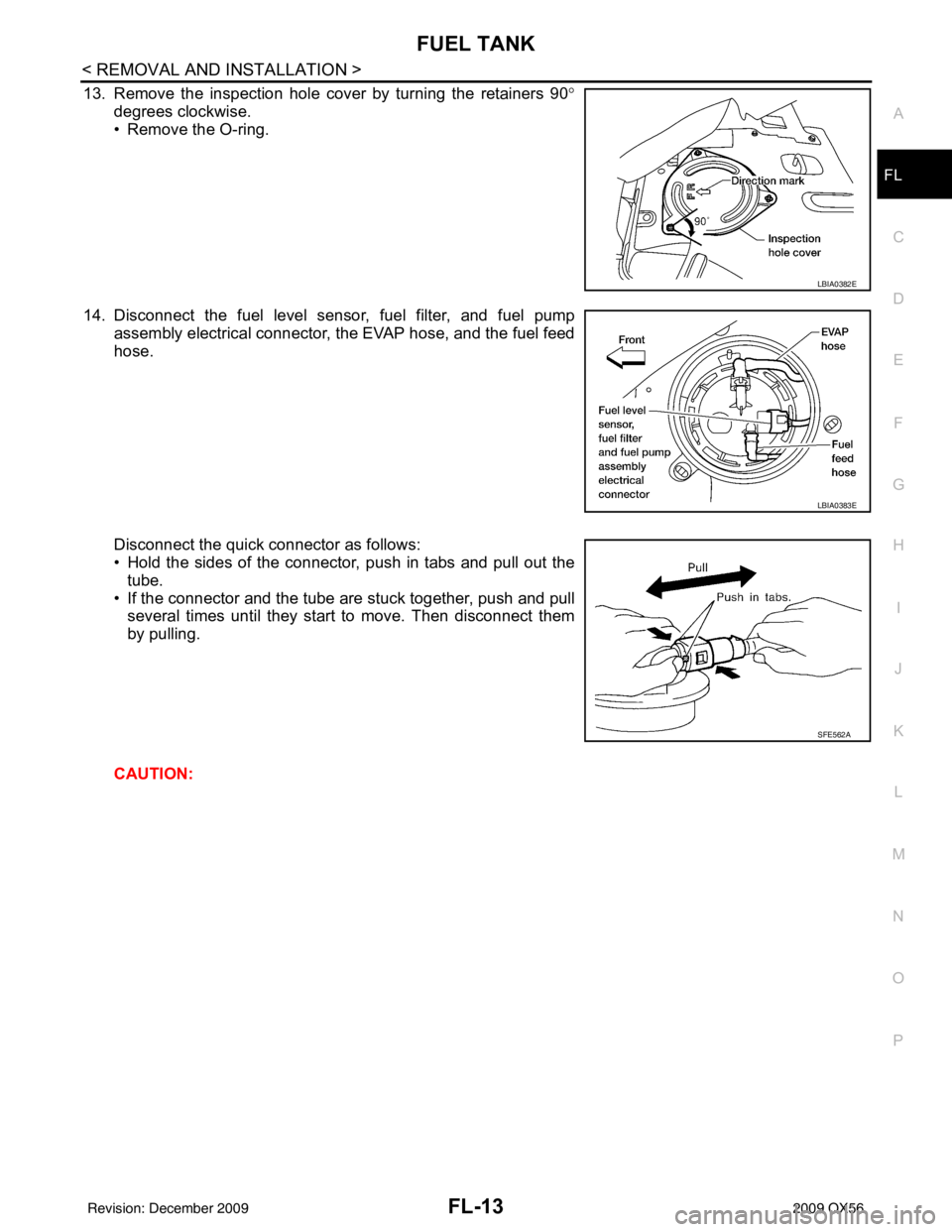
13. Remove the inspection hole cover by turning the retainers 90
°
degrees clockwise.
• Remove the O-ring.
14. Disconnect the fuel level sensor, fuel filter, and fuel pump assembly electrical connector, the EVAP hose, and the fuel feed
hose.
Disconnect the quick connector as follows:
• Hold the sides of the connector, push in tabs and pull out the
tube.
• If the connector and the tube are stuck together, push and pull several times until they start to move. Then disconnect them
by pulling.
CAUTION:
LBIA0382E
LBIA0383E
SFE562A
Revision: December 20092009 QX56
Page 2167 of 4171
FL-14
< REMOVAL AND INSTALLATION >
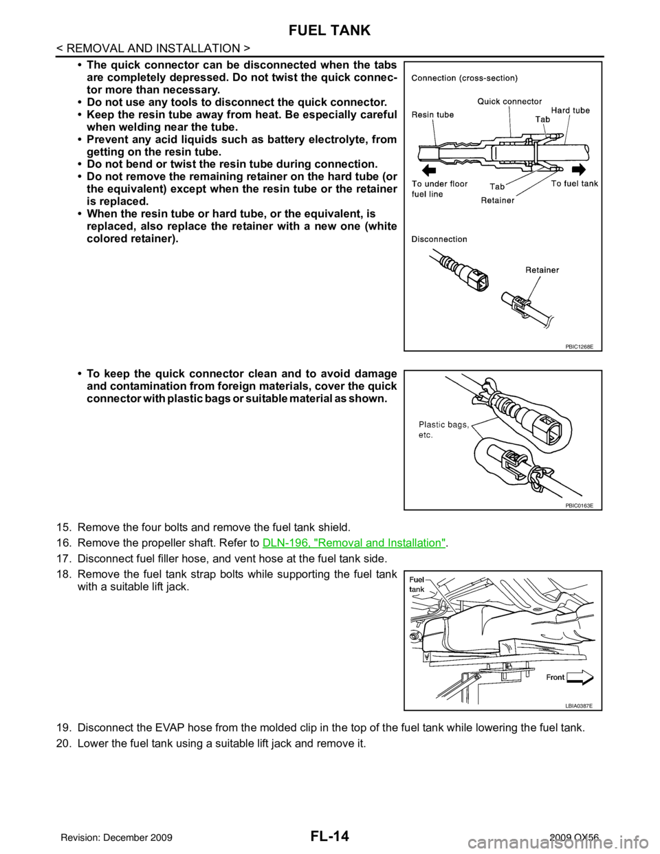
FUEL TANK
• The quick connector can be disconnected when the tabsare completely depressed. Do not twist the quick connec-
tor more than necessary.
• Do not use any tools to di sconnect the quick connector.
• Keep the resin tube away from heat. Be especially careful
when welding near the tube.
• Prevent any acid liquids such as battery electrolyte, from getting on the resin tube.
• Do not bend or twist the resin tube during connection.
• Do not remove the remaining retainer on the hard tube (or
the equivalent) except when the resin tube or the retainer
is replaced.
• When the resin tube or hard tube, or the equivalent, is
replaced, also replace the retainer with a new one (white
colored retainer).
• To keep the quick connector clean and to avoid damage
and contamination from foreign materials, cover the quick
connector with plastic bags or suit able material as shown.
15. Remove the four bolts and remove the fuel tank shield.
16. Remove the propeller shaft. Refer to DLN-196, "
Removal and Installation".
17. Disconnect fuel filler hose, and vent hose at the fuel tank side.
18. Remove the fuel tank strap bolts while supporting the fuel tank with a suitable lift jack.
19. Disconnect the EVAP hose from the molded clip in the top of the fuel tank while lowering the fuel tank.
20. Lower the fuel tank using a suitable lift jack and remove it.
PBIC1268E
PBIC0163E
LBIA0387E
Revision: December 20092009 QX56