2009 INFINITI QX56 fuel tank removal
[x] Cancel search: fuel tank removalPage 2168 of 4171
FUEL TANKFL-15
< REMOVAL AND INSTALLATION >
C
DE
F
G H
I
J
K L
M A
FL
NP
O
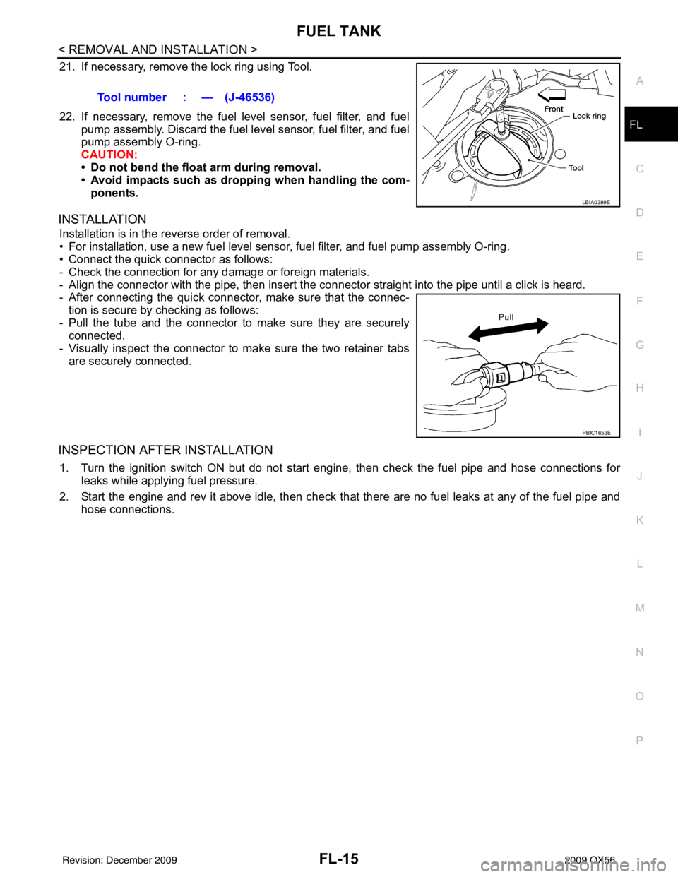
21. If necessary, remove the lock ring using Tool.
22. If necessary, remove the fuel level sensor, fuel filter, and fuel
pump assembly. Discard the fuel level sensor, fuel filter, and fuel
pump assembly O-ring.
CAUTION:
• Do not bend the float arm during removal.
• Avoid impacts such as droppi ng when handling the com-
ponents.
INSTALLATION
Installation is in the reverse order of removal.
• For installation, use a new fuel level sensor, fuel filter, and fuel pump assembly O-ring.
• Connect the quick connector as follows:
- Check the connection for any damage or foreign materials.
- Align the connector with the pipe, t hen insert the connector straight into the pipe until a click is heard.
- After connecting the quick connector, make sure that the connec-
tion is secure by checking as follows:
- Pull the tube and the connector to make sure they are securely connected.
- Visually inspect the connector to make sure the two retainer tabs are securely connected.
INSPECTION AFTER INSTALLATION
1. Turn the ignition switch ON but do not start en gine, then check the fuel pipe and hose connections for
leaks while applying fuel pressure.
2. Start the engine and rev it above idle, then check that there are no fuel leaks at any of the fuel pipe and
hose connections. Tool number : — (J-46536)
LBIA0389E
PBIC1653E
Revision: December 20092009 QX56
Page 2221 of 4171
PRECAUTIONSGI-27
< PRECAUTION >
C
DE
F
G H
I
J
K L
M B
GI
N
O P
system. The connectors should be disconnected only when working according to the WORK FLOW of
TROUBLE DIAGNOSES in EC and TM sections.
Three Way CatalystINFOID:0000000003771200
If a large amount of unburned fuel flows into the catalyst, the catalyst temperature will be excessively high. To
prevent this, follow the instructions.
• Use unleaded gasoline only. Leaded gasoline will seriously damage the three way catalyst.
• When checking for ignition spark or measuring engine compression, make tests quickly and only when nec-
essary.
• Do not run engine when the fuel tank level is low, otherwise the engine may misfire, causing damage to the
catalyst.
Do not place the vehicle on flammable material. Keep flammable material off the exhaust pipe and the three
way catalyst.
Precaution for Fuel (Unlead ed Premium Gasoline Recommended)INFOID:0000000005892332
NISSAN/INFINITI recommends the us e of unleaded premium gasoline with an octane rating of at least 91 AKI
(Anti-Knock Index) number (Research octane number 96). If unleaded premium gasoline is not available,
unleaded regular gasoline with an octane rating of at least 87 AKI number (Research octane number 91), but
you may notice a decrease in performance.
CAUTION:
Do not use leaded gasoline. Usin g leaded gasoline will damage the three way catalyst. Using a fuel
other than that specified could adversely affect the emission cont rol devices and systems, and could
also affect the warranty coverage validity.
CAUTION:
Do not use E-85 fuel in your vehicle. Your vehicle is not designed to run on E-85 fuel. Using E-85 fuel
can cause damage to the fuel system components an d is not covered by the INFINTI vehicle limited
warranty.
Multiport Fuel Inje ction System or Engine Control SystemINFOID:0000000003771202
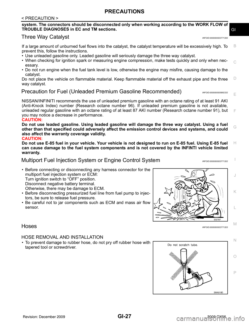
• Before connecting or disconnecting any harness connector for the
multiport fuel injection system or ECM:
Turn ignition switch to “OFF” position.
Disconnect negative battery terminal.
Otherwise, there may be damage to ECM.
• Before disconnecting pressurized fuel line from fuel pump to injec- tors, be sure to release fuel pressure.
• Be careful not to jar components such as ECM and mass air flow sensor.
HosesINFOID:0000000003771203
HOSE REMOVAL AND INSTALLATION
• To prevent damage to rubber hose, do not pry off rubber hose withtapered tool or screwdriver.
SGI787
SMA019D
Revision: December 20092009 QX56
Page 2690 of 4171
ENGINE MAINTENANCEMA-17
< ON-VEHICLE MAINTENANCE >
C
DE
F
G H
I
J
K L
M B
MA
N
O A
2. Fill the radiator and the reservoir tank (to the “MAX”
line), with water. Reinstall the radiator cap and leave
the vented reservoir cap off.
3. Run the engine until it reaches normal operating temperature.
4. Press the engine accelerator two or three times under no-load.
5. Stop the engine and wait until it cools down.
6. Drain the water from the engine cooling system.
7. Repeat steps 2 through 6 until clear water begins to drain from the radiator.
Checking Fuel LineINFOID:0000000004215533
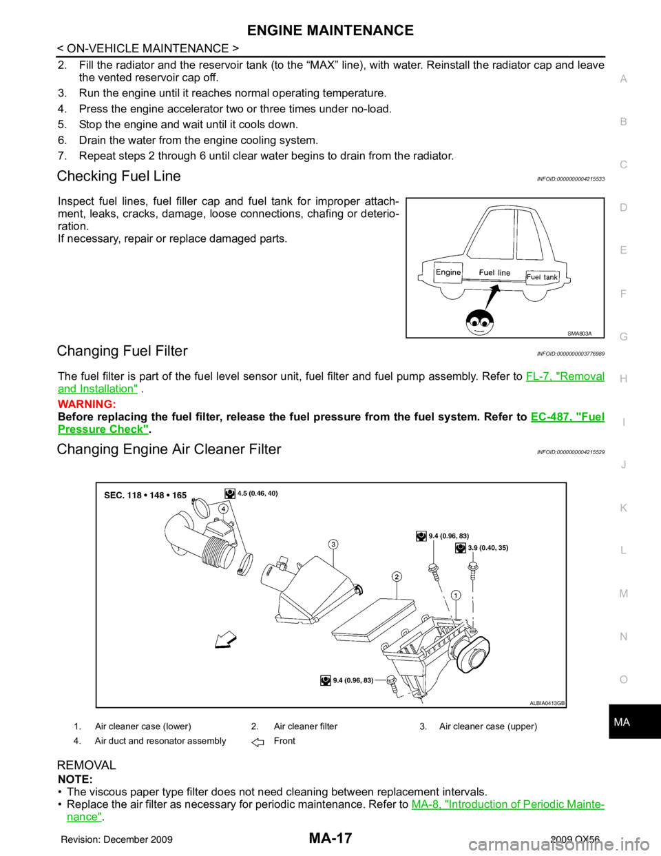
Inspect fuel lines, fuel filler cap and fuel tank for improper attach-
ment, leaks, cracks, damage, loos e connections, chafing or deterio-
ration.
If necessary, repair or replace damaged parts.
Changing Fuel FilterINFOID:0000000003776989
The fuel filter is part of the fuel level sensor unit, fuel filter and fuel pump assembly. Refer to FL-7, "Removal
and Installation" .
WARNING:
Before replacing the fuel filter, release the fuel pressure from the fuel system. Refer to EC-487, "
Fuel
Pressure Check".
Changing Engine Air Cleaner FilterINFOID:0000000004215529
REMOVAL
NOTE:
• The viscous paper type filter does not need cleaning between replacement intervals.
• Replace the air filter as necessary for periodic maintenance. Refer to MA-8, "
Introduction of Periodic Mainte-
nance".
SMA803A
1. Air cleaner case (lower)2. Air cleaner filter3. Air cleaner case (upper)
4. Air duct and resonator assembly Front
ALBIA0413GB
Revision: December 20092009 QX56
Page 2755 of 4171
MWI
FUEL LEVEL SENSOR SIGNAL CIRCUITMWI-33
< COMPONENT DIAGNOSIS >
C
DE
F
G H
I
J
K L
M B A
O P
FUEL LEVEL SENSOR SIGNAL CIRCUIT
DescriptionINFOID:0000000003776636
The fuel level sensor unit and fuel pump detects the approx imate fuel level in the fuel tank and transmits the
fuel level signal to the combination meter.
Component Function CheckINFOID:0000000003776637
1.COMBINATION METER INPUT SIGNAL
1. Select “METER/M&A” on CONSULT-III.
2. Using “FUEL METER” of “DATA MONITOR”, comp are the value of DATA MONITOR with fuel gauge
pointer of combination meter.
Does the data monitor value approximately match the fuel gauge indication?
YES >> Inspection End.
NO >> Replace combination meter. Refer to MWI-102, "
Removal and Installation".
Diagnosis ProcedureINFOID:0000000003776638
1.CHECK HARNESS CONNECTOR
1. Turn ignition switch OFF.
2. Check combination meter and fuel level sensor unit terminals (meter-side and harness-side) for poor con- nection.
Is the inspection result normal?
YES >> GO TO 2
NO >> Repair or replace terminals or connectors.
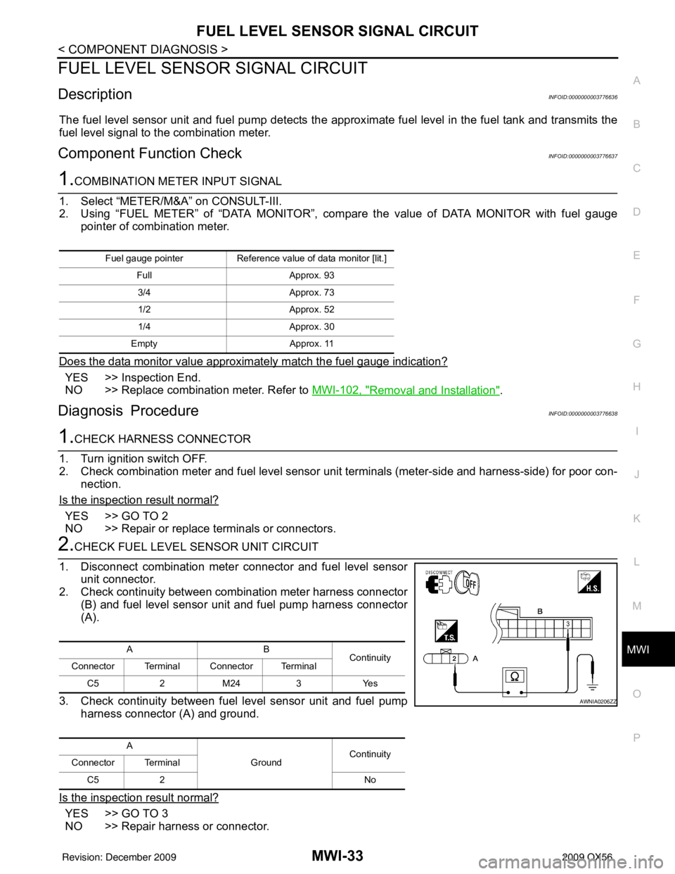
2.CHECK FUEL LEVEL SENSOR UNIT CIRCUIT
1. Disconnect combination meter connector and fuel level sensor unit connector.
2. Check continuity between combination meter harness connector
(B) and fuel level sensor unit and fuel pump harness connector
(A).
3. Check continuity between fuel level sensor unit and fuel pump harness connector (A) and ground.
Is the inspection result normal?
YES >> GO TO 3
NO >> Repair harness or connector.
Fuel gauge pointer Reference value of data monitor [lit.]
Full Approx. 93
3/4 Approx. 73
1/2 Approx. 52
1/4 Approx. 30
Empty Approx. 11
AB
Continuity
Connector Terminal Connector Terminal
C5 2 M24 3 Yes
A GroundContinuity
Connector Terminal
C5 2 No
AWNIA0206ZZ
Revision: December 20092009 QX56
Page 2756 of 4171

MWI-34
< COMPONENT DIAGNOSIS >
FUEL LEVEL SENSOR SIGNAL CIRCUIT
3.CHECK FUEL LEVEL SENSOR UNIT GROUND CIRCUIT
1. Check continuity between combination meter harness connector (B) and fuel level sensor uni t and fuel pump harness connector
(A).
2. Check continuity between fuel level sensor unit and fuel pump harness connector (A) and ground.
Is the inspection result normal?
YES >> GO TO 4
NO >> Repair harness or connector.
4.CHECK INSTALLATION CONDITION
Check fuel level sensor unit installation, and check whether the float arm interferes or binds with any of the
internal components in the fuel tank.
Is the inspection result normal?
YES >> Inspection End.
NO >> Install the fuel level sensor unit properly.
Component InspectionINFOID:0000000003776639
1.REMOVE FUEL LEVEL SENSOR UNIT
Remove the fuel level sensor unit. Refer to FL-7, "
Removal and Installation".
>> GO TO 2
2.CHECK FUEL LEVEL SENSOR UNIT AND FUEL PUMP
Check the resistance between terminals 2 and 5.
*1 and *2: When float arm is in contact with stopper.
Is inspection result normal?
YES >> Inspection End.
NO >> Replace fuel level sensor unit and fuel pump. Refer to FL-7, "
Removal and Installation".
AB Continuity
Connector Terminal Connector Terminal
C5 5 M24 4 Yes
A GroundContinuity
Connector Terminal
C5 5 No
AWNIA0207ZZ
Te r m i n a l Float position
mm (in) Resistance value
(Approx.)
25 *1 Empty
7.5 (0.3)80Ω
*2 Full 218.9 (8.6)6Ω
LKIA0402E
Revision: December 20092009 QX56
Page 2814 of 4171
MWI-92
< SYMPTOM DIAGNOSIS >
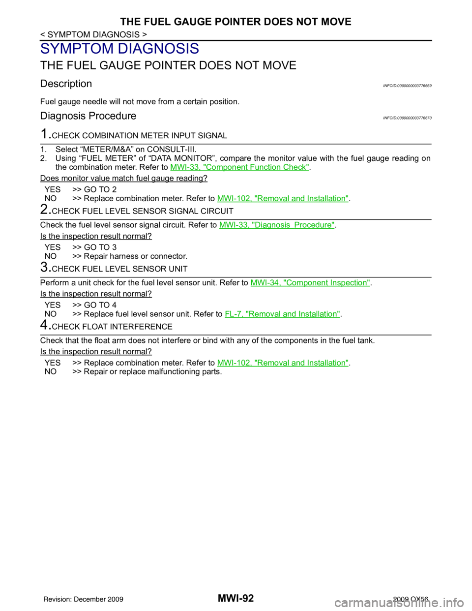
THE FUEL GAUGE POINTER DOES NOT MOVE
SYMPTOM DIAGNOSIS
THE FUEL GAUGE POINTER DOES NOT MOVE
DescriptionINFOID:0000000003776669
Fuel gauge needle will not move from a certain position.
Diagnosis ProcedureINFOID:0000000003776670
1.CHECK COMBINATION METER INPUT SIGNAL
1. Select “METER/M&A” on CONSULT-III.
2. Using “FUEL METER” of “DATA MONITOR”, comp are the monitor value with the fuel gauge reading on
the combination meter. Refer to MWI-33, "
Component Function Check".
Does monitor value match fuel gauge reading?
YES >> GO TO 2
NO >> Replace combination meter. Refer to MWI-102, "
Removal and Installation".
2.CHECK FUEL LEVEL SENSOR SIGNAL CIRCUIT
Check the fuel level sensor signal circuit. Refer to MWI-33, "
DiagnosisProcedure".
Is the inspection result normal?
YES >> GO TO 3
NO >> Repair harness or connector.
3.CHECK FUEL LEVEL SENSOR UNIT
Perform a unit check for the fuel level sensor unit. Refer to MWI-34, "
Component Inspection".
Is the inspection result normal?
YES >> GO TO 4
NO >> Replace fuel level sensor unit. Refer to FL-7, "
Removal and Installation".
4.CHECK FLOAT INTERFERENCE
Check that the float arm does not interfere or bi nd with any of the components in the fuel tank.
Is the inspection result normal?
YES >> Replace combination meter. Refer to MWI-102, "Removal and Installation".
NO >> Repair or replace malfunctioning parts.
Revision: December 20092009 QX56
Page 3162 of 4171
RSU-14
< REMOVAL AND INSTALLATION >
REAR SUSPENSION MEMBER
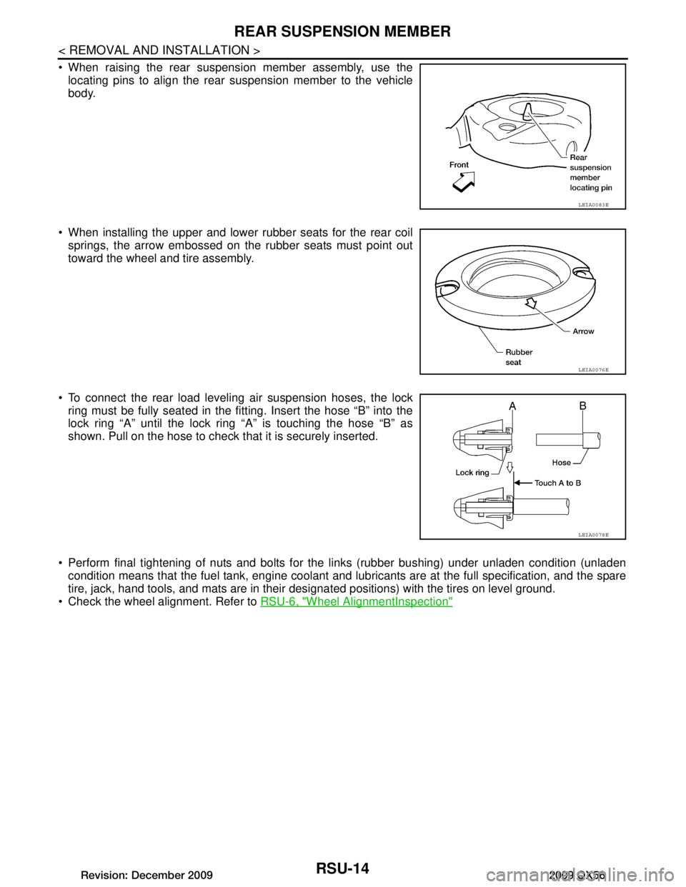
When raising the rear suspension member assembly, use thelocating pins to align the rear suspension member to the vehicle
body.
When installing the upper and lower rubber seats for the rear coil springs, the arrow embossed on the rubber seats must point out
toward the wheel and tire assembly.
To connect the rear load leveling air suspension hoses, the lock ring must be fully seated in the fitt ing. Insert the hose “B” into the
lock ring “A” until the lock ring “A” is touching the hose “B” as
shown. Pull on the hose to check that it is securely inserted.
Perform final tightening of nuts and bolts for the links (rubber bushing) under unladen condition (unladen condition means that the fuel tank, engine coolant and l ubricants are at the full specification, and the spare
tire, jack, hand tools, and mats are in their designated positions) with the tires on level ground.
Check the wheel alignment. Refer to RSU-6, "Wheel AlignmentInspection"
LEIA0083E
LEIA0076E
LEIA0078E
Revision: December 20092009 QX56
Page 3166 of 4171

RSU-18
< REMOVAL AND INSTALLATION >
SUSPENSION ARM
17. Remove the two bolts to disconnect the seat belt latch anchorfrom the rear suspension member.
18. Disconnect both of the connecting rods from the front lower link.
19. Set a suitable jack under the rear suspension member.
20. Remove the six rear suspension member bolts.
21. Slowly lower the jack to remove the rear suspension member assembly.
22. Remove suspension arm from rear suspension member.
INSPECTION AFTER REMOVAL
Check suspension arm for damage, cracks, deformation and replace if necessary.
Check rubber bushing for damage, cracks and deformation. Replace suspension arm assembly if neces- sary.
Before checking, turn ball joint at least 10 revolutions so that ball joint is properly broken in.
Check ball joint. Replace suspension arm assembly if any of the following exists:
- Ball stud is worn.
- Joint is hard to swing.
- Play in axial direction is excessive.
INSTALLATION
Installation is in the reverse order of removal.
Tighten the nuts and bolts to specification. Refer to RSU-11, "Removal and Installation"
.
Perform final tightening of nuts and bolts for the links (rubber bushing) under unladen condition (unladen
condition means that the fuel tank, engine coolant and l ubricants are at the full specification, and the spare
tire, jack, hand tools, and mats are in their designated positions) with the tires on level ground.
Check the wheel alignment. Refer to RSU-29, "Wheel Alignment (Unladen
*1)".
LEIA0075E
Swinging force (A) : Refer to RSU-29, "Ball Joint"
Turning force (B) : Refer to RSU-29, "Ball Joint"
Vertical end play (C) : Refer to RSU-29, "Ball Joint"
SFA858A
Revision: December 20092009 QX56