2009 INFINITI QX56 parking brake
[x] Cancel search: parking brakePage 1345 of 4171
![INFINITI QX56 2009 Factory Service Manual
EC-18
< BASIC INSPECTION >[VK56DE]
INSPECTION AND ADJUSTMENT
With CONSULT-III
1. Check the VIN of the vehicle and note it. Refer to
GI-20, "Model Variation".
2. Turn ignition switch ON and engine s INFINITI QX56 2009 Factory Service Manual
EC-18
< BASIC INSPECTION >[VK56DE]
INSPECTION AND ADJUSTMENT
With CONSULT-III
1. Check the VIN of the vehicle and note it. Refer to
GI-20, "Model Variation".
2. Turn ignition switch ON and engine s](/manual-img/42/57031/w960_57031-1344.png)
EC-18
< BASIC INSPECTION >[VK56DE]
INSPECTION AND ADJUSTMENT
With CONSULT-III
1. Check the VIN of the vehicle and note it. Refer to
GI-20, "Model Variation".
2. Turn ignition switch ON and engine stopped.
3. Select “VIN REGISTRATION ” in “WORK SUPPORT” mode.
4. Follow the instruction of CONSULT-III display.
Accelerator Pedal Released Position LearningINFOID:0000000003771298
DESCRIPTION
Accelerator Pedal Released Position Learning is an operati on to learn the fully released position of the accel-
erator pedal by monitoring the accelerator pedal positi on sensor output signal. It must be performed each time
harness connector of accelerator pedal pos ition sensor or ECM is disconnected.
OPERATION PROCEDURE
1. Make sure that accelerator pedal is fully released.
2. Turn ignition switch ON and wait at least 2 seconds.
3. Turn ignition switch OFF and wait at least 10 seconds.
4. Turn ignition switch ON and wait at least 2 seconds.
5. Turn ignition switch OFF and wait at least 10 seconds.
Throttle Valve Closed Position LearningINFOID:0000000003771299
DESCRIPTION
Throttle Valve Closed Position Learning is an operation to l earn the fully closed position of the throttle valve by
monitoring the throttle position sensor output signal . It must be performed each time harness connector of
electric throttle control actuator or ECM is disconnected.
OPERATION PROCEDURE
1. Make sure that accelerator pedal is fully released.
2. Turn ignition switch ON.
3. Turn ignition switch OFF wait at least 10 seconds. Make sure that throttle valve moves during above 10 seconds by confirming the operating sound.
Idle Air Volume LearningINFOID:0000000003771300
DESCRIPTION
Idle Air Volume Learning is an operation to learn the idle air volume that keeps each engine within the specific
range. It must be performed under any of the following conditions:
Each time electric throttle control actuator or ECM is replaced.
Idle speed or ignition timing is out of specification.
PREPARATION
Before performing Idle Air Volume Learning, make sure that all of the following conditions are satisfied.
Learning will be cancelled if any of the following conditions are missed for even a moment.
Battery voltage: More than 12.9V (At idle)
Engine coolant temperature: 70 - 100 °C (158 - 212 °F)
Select lever: P or N
Electric load switch: OFF (Air conditioner, headlamp, rear window defogger)
On vehicles equipped with daytime light systems, if the parking brake is applied before the engine is
start the headlamp will not be illuminated.
Steering wheel: Neutral (Straight-ahead position)
Vehicle speed: Stopped
Transmission: Warmed-up
- With CONSULT-III: Drive vehicle until “ATF TEMP SE 1” in “DATA MONITOR” mode of “A/T” system indi-
cates less than 0.9V.
- Without CONSULT-III: Drive vehicle for 10 minutes.
OPERATION PROCEDURE
Revision: December 20092009 QX56
Page 1957 of 4171

DAYTIME LIGHT SYSTEMEXL-9
< FUNCTION DIAGNOSIS >
C
DE
F
G H
I
J
K
M A
B
EXL
N
O P
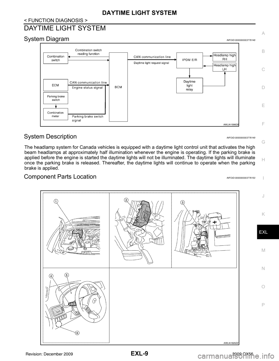
DAYTIME LIGHT SYSTEM
System DiagramINFOID:0000000003776148
System DescriptionINFOID:0000000003776149
The headlamp system for Canada vehicles is equipped with a daytime light control unit that activates the high
beam headlamps at approximately half illumination whenever the engine is operating. If the parking brake is
applied before the engine is started the daytime lights will not be illuminated. The daytime lights will illuminate
once the parking brake is released. Thereafter, the daytime lights will continue to operate when the parking
brake is applied.
Component Parts LocationINFOID:0000000003776150
AWLIA1596GB
AWLIA1626ZZ
Revision: December 20092009 QX56
Page 1958 of 4171

EXL-10
< FUNCTION DIAGNOSIS >
DAYTIME LIGHT SYSTEM
Component Description
INFOID:0000000003776151
After starting the engine with the parking brake released and the lighting switch in the OFF or 1ST position, the
headlamp high beam automatically turns on at a reduced intensity. With the lighting switch in the 2nd position
or with autolamps ON, the headlamps function the same as conventional light systems.
OPERATION
The BCM monitors inputs from the parking brake switch and the combination switch to determine when to acti-
vate the daytime light system. The BCM sends a dayti me light request to the IPDM E/R via the CAN commu-
nication lines. The IPDM E/R grounds the daytime light relay which in turn, provides power to the ground side
of the LH high beam lamp. Power flows backward through the LH high beam lamp to the IPDM E/R, through
the high beam fuses, through the RH high beam lamp circuit to the RH high beam lamp and on to ground. The
high beam lamps are wired in series which causes them to illuminate at a reduced intensity.
1. IPDM E/R E119, E122, E123, E124 2. BCM M18, M20 (view with instrument
panel removed)3. Daytime running light relay E103
4. Combination switch M28 5. Combination meter M23, M24 6. Parking brake switch M11
Revision: December 20092009 QX56
Page 1967 of 4171

TRAILER TOWEXL-19
< FUNCTION DIAGNOSIS >
C
DE
F
G H
I
J
K
M A
B
EXL
N
O P
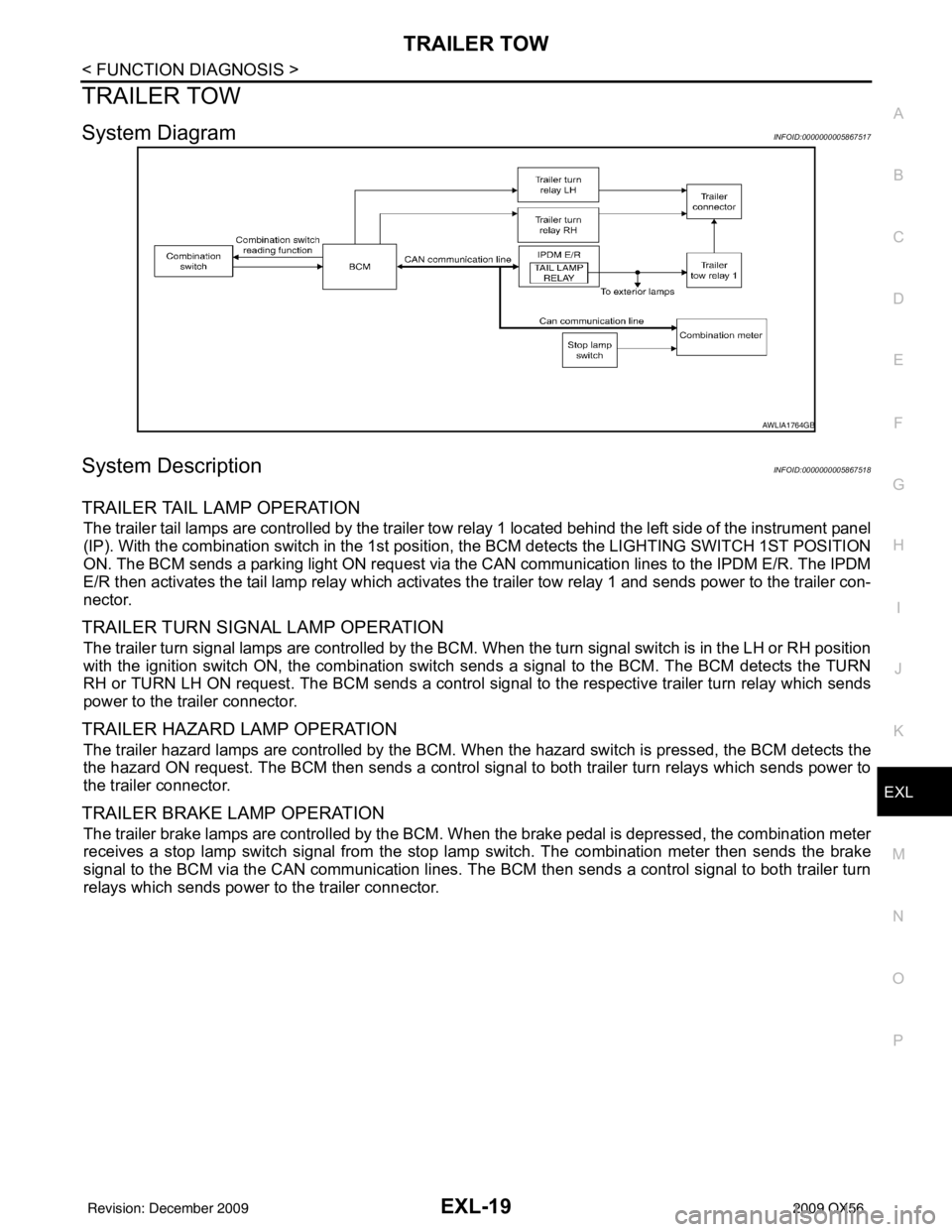
TRAILER TOW
System DiagramINFOID:0000000005867517
System DescriptionINFOID:0000000005867518
TRAILER TAIL LAMP OPERATION
The trailer tail lamps are controlled by the trailer tow re lay 1 located behind the left side of the instrument panel
(IP). With the combination switch in the 1st position, the BCM detects the LI GHTING SWITCH 1ST POSITION
ON. The BCM sends a parking light ON request via the CAN communication lines to the IPDM E/R. The IPDM
E/R then activates the tail lamp relay which activates t he trailer tow relay 1 and sends power to the trailer con-
nector.
TRAILER TURN SIGNAL LAMP OPERATION
The trailer turn signal lamps are controlled by the BCM. When the turn signal switch is in the LH or RH position
with the ignition switch ON, the combination switch sends a signal to the BCM. The BCM detects the TURN
RH or TURN LH ON request. The BCM sends a control signal to the respective trailer turn relay which sends
power to the trailer connector.
TRAILER HAZARD LAMP OPERATION
The trailer hazard lamps are controlled by the BCM. When the hazard switch is pressed, the BCM detects the
the hazard ON request. The BCM then sends a control signal to both trailer turn relays which sends power to
the trailer connector.
TRAILER BRAKE LAMP OPERATION
The trailer brake lamps are controlled by the BCM. W hen the brake pedal is depressed, the combination meter
receives a stop lamp switch signal from the stop lamp switch. The combination meter then sends the brake
signal to the BCM via the CAN communication lines. The BCM then sends a control signal to both trailer turn
relays which sends power to the trailer connector.
AWLIA1764GB
Revision: December 20092009 QX56
Page 2083 of 4171

EXTERIOR LIGHTING SYSTEM SYMPTOMSEXL-135
< SYMPTOM DIAGNOSIS >
C
DE
F
G H
I
J
K
M A
B
EXL
N
O P
Daytime light system does not activate. • Either high beam bulb
• Parking brake switch
• Combination switch
•BCM
• IPDM E/R
• Daytime light relay
• Harness between IPDM E/R
and daytime light relay. Daytime light system description.
Refer to
EXL-9, "System Descrip-
tion".
Front fog lamp is not
turned ON. One side
• Front fog lamp bulb
• Harness between IPDM E/R
and the front combination lamp
• Front combination lamp
• IPDM E/R Front fog lamp circuit
Refer to
EXL-38
.
Both sides Symptom diagnosis
"BOTH SIDE FRONT FOG LAMPS ARE NOT TURNED ON"
Refer to EXL-140
.
Parking lamp is not turned
ON. One side•Fuse
• Parking lamp bulb
• Harness between IPDM E/R
and the front/rear combination
lamp
• Front/rear combination lamp
• IPDM E/R Parking lamp circuit
Refer to
EXL-40
.
Both sides Symptom diagnosis
"PARKING, LICENSE PLATE AND TAIL LAMPS ARE NOT TURNED
ON"
Refer to EXL-139
.
Turn signal lamp does not
blink. Indicator lamp is nor-
mal.
(The applicable side
performs the high flash-
er activation).• Harness between BCM and
each turn signal lamp
• Turn signal lamp bulb
• Door mirror (if equipped with
turn signals in the door mirrors) Turn signal lamp circuit
Refer to
EXL-46
.
Turn signal indicator lamp
does not blink. One side
Combination meter —
Both sides
(Always) • Turn signal indicator lamp sig-
nal
• Combination meter
•BCM • Combination meter.
Data monitor "TURN IND".
• BCM (FLASHER)
Active test "FLASHER".
Both sides
(Does blink when acti-
vating the hazard warn-
ing lamp with the
ignition switch OFF) • The combination meter power
supply and the ground circuit
• Combination meter Combination meter
Power supply and the ground circuit
Refer to
MWI-30
.
Symptom
Possible causeInspection item
Revision: December 20092009 QX56
Page 2206 of 4171

GI-12
< HOW TO USE THIS MANUAL >
HOW TO READ WIRING DIAGRAMS
• ignition switch is “OFF”,
• doors, hood and trunk lid/back door are closed,
• pedals are not depressed, and
• parking brake is released.
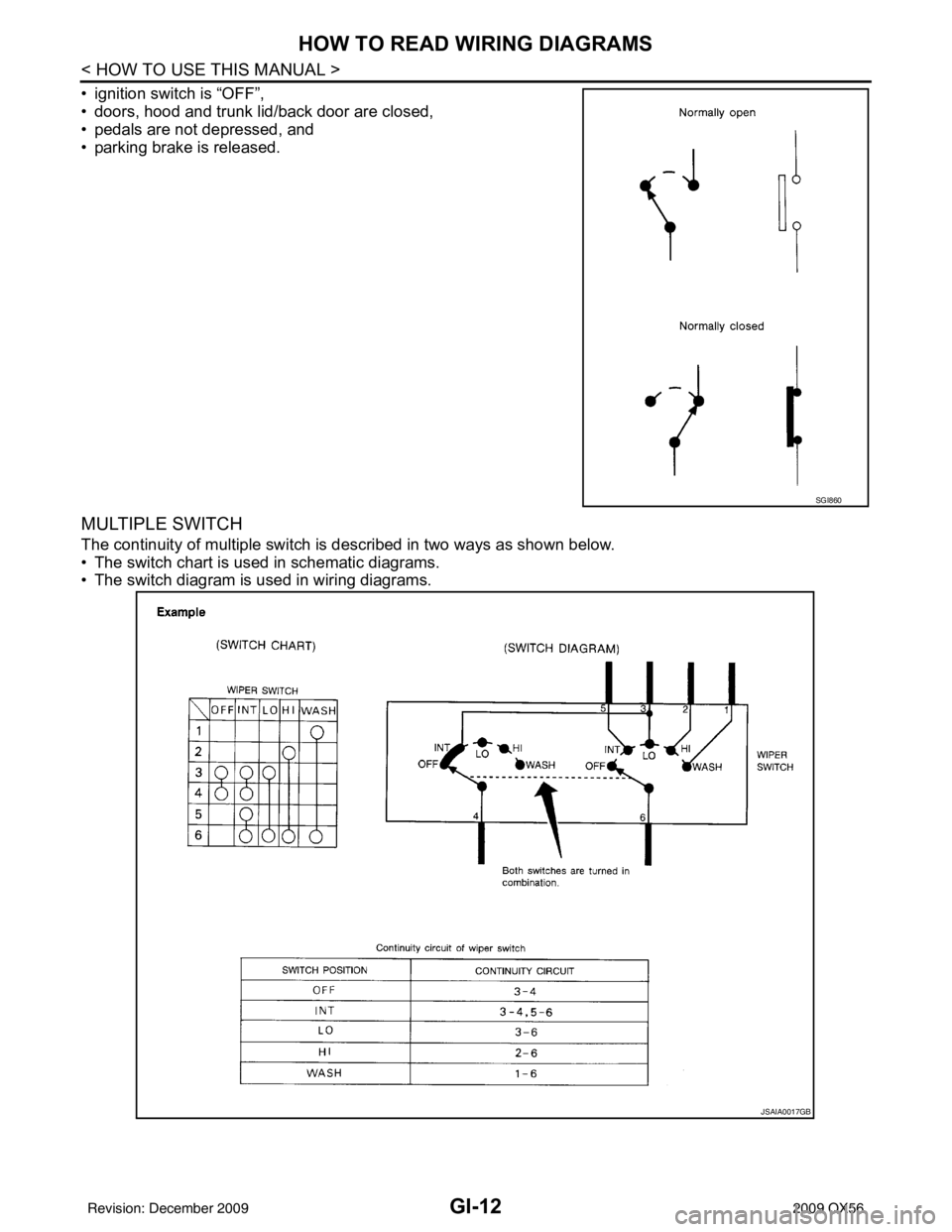
MULTIPLE SWITCH
The continuity of multiple switch is described in two ways as shown below.
• The switch chart is used in schematic diagrams.
• The switch diagram is used in wiring diagrams.
SGI860
JSAIA0017GB
Revision: December 20092009 QX56
Page 2615 of 4171
![INFINITI QX56 2009 Factory Service Manual LAN-46
< FUNCTION DIAGNOSIS >[CAN]
CAN COMMUNICATION SYSTEM
NOTE:
CAN data of the air bag diagnosis sensor unit is not us
ed by usual service work, thus it is omitted.
Tire pressure data signal R T
T INFINITI QX56 2009 Factory Service Manual LAN-46
< FUNCTION DIAGNOSIS >[CAN]
CAN COMMUNICATION SYSTEM
NOTE:
CAN data of the air bag diagnosis sensor unit is not us
ed by usual service work, thus it is omitted.
Tire pressure data signal R T
T](/manual-img/42/57031/w960_57031-2614.png)
LAN-46
< FUNCTION DIAGNOSIS >[CAN]
CAN COMMUNICATION SYSTEM
NOTE:
CAN data of the air bag diagnosis sensor unit is not us
ed by usual service work, thus it is omitted.
Tire pressure data signal R T
Tire pressure signal R TR
Turn indicator signal TR
Buzzer output signal TR
Door lock/unlock request signal RT
Hazard request signal RT
Hazard warning lamp request signal RT
Ignition knob switch signal RT
KEY warning signal TR
LOCK warning signal TR
Panic alarm request signal RT
Power window open request signal RT
1st position switch signal R T
4th position switch signal R T
Distance to empty signal RT
Fuel level low warning signal RT
Fuel level sensor signal R T
Parking brake switch signal RT
Seat belt buckle switch signal RT
Stop lamp switch signal R T
Tow mode switch signal R T
Vehicle speed signal RRR RRR R T
RRRT
Steering angle sensor signal TR
ABS malfunction signal RT
ABS warning lamp signal RT
Brake pressure sensor signal RT
Brake warning lamp signal RT
SLIP indicator lamp signal RT
TCS malfunction signal RT
VDC malfunction signal RT
VDC OFF indicator lamp signal RRT
VDC operation signal RT
Front wiper stop position signal RT
High beam status signal R T
Hood switch signal RT
Low beam status signal R T
Rear window defogger control signal R RT
Signal name/Connecting unit
ECM
TCM
LASER ICC
ADP
AV
BCM
HVAC I-KEY M&A
STRG 4WDABS
IPDM-E
Revision: December 20092009 QX56
Page 2680 of 4171

GENERAL MAINTENANCEMA-7
< ON-VEHICLE MAINTENANCE >
C
DE
F
G H
I
J
K L
M B
MA
N
O A
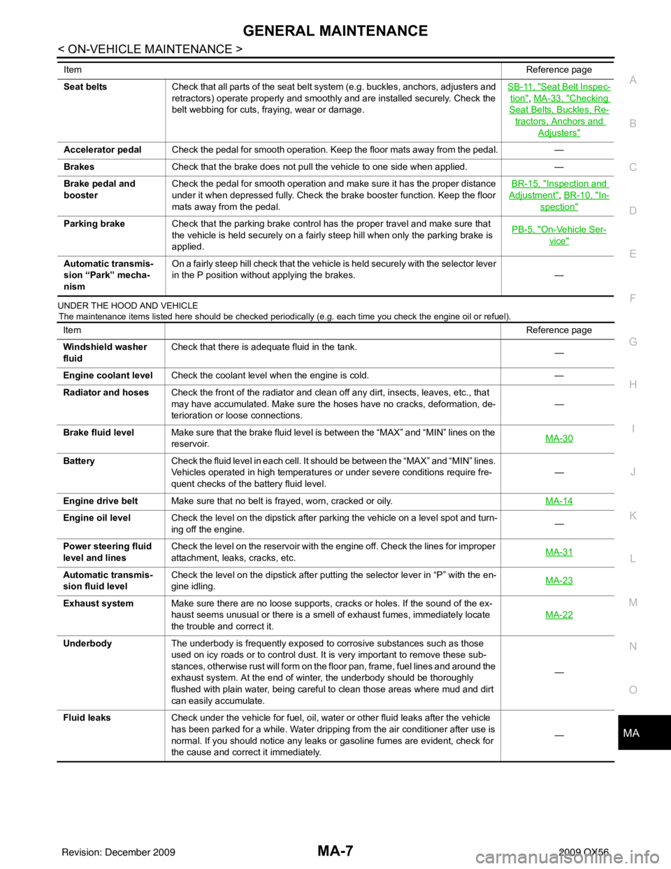
UNDER THE HOOD AND VEHICLE
The maintenance items listed here should be checked periodically (e.g. each time you check the engine oil or refuel).
Seat beltsCheck that all parts of the seat belt system (e.g. buckles, anchors, adjusters and
retractors) operate properly and smoothly and are installed securely. Check the
belt webbing for cuts, fraying, wear or damage. SB-11, "Seat Belt Inspec-
tion", MA-33, "Checking
Seat Belts, Buckles, Re-
tractors, Anchors and
Adjusters"
Accelerator pedal
Check the pedal for smooth operation. Keep the floor mats away from the pedal. —
Brakes Check that the brake does not pull the vehicle to one side when applied. —
Brake pedal and
booster Check the pedal for smooth operation and make sure it has the proper distance
under it when depressed fully. Check the brake booster function. Keep the floor
mats away from the pedal. BR-15, "
Inspection and
Adjustment", BR-10, "In-
spection"
Parking brake
Check that the parking brake control has the proper travel and make sure that
the vehicle is held securely on a fairly steep hill when only the parking brake is
applied. PB-5, "On-Vehicle Ser-
vice"
Automatic transmis-
sion “Park” mecha-
nismOn a fairly steep hill check that the vehicle is held securely with the selector lever
in the P position without applying the brakes.
—
Item
Reference page
Item Reference page
Windshield washer
fluid Check that there is adequate fluid in the tank.
—
Engine coolant level Check the coolant level when the engine is cold. —
Radiator and hoses Check the front of the radiator and clean off any dirt, insects, leaves, etc., that
may have accumulated. Make sure the hoses have no cracks, deformation, de-
terioration or loose connections. —
Brake fluid level Make sure that the brake fluid level is between the “MAX” and “MIN” lines on the
reservoir. MA-30
Battery
Check the fluid level in each cell. It should be between the “MAX” and “MIN” lines.
Vehicles operated in high temperatures or under severe conditions require fre-
quent checks of the battery fluid level. —
Engine drive belt Make sure that no belt is frayed, worn, cracked or oily. MA-14
Engine oil levelCheck the level on the dipstick after parking the vehicle on a level spot and turn-
ing off the engine. —
Power steering fluid
level and lines Check the level on the reservoir with the engine off. Check the lines for improper
attachment, leaks, cracks, etc.
MA-31
Automatic transmis-
sion fluid levelCheck the level on the dipstick after putting the selector lever in “P” with the en-
gine idling.
MA-23
Exhaust system
Make sure there are no loose supports, cracks or holes. If the sound of the ex-
haust seems unusual or there is a smell of exhaust fumes, immediately locate
the trouble and correct it. MA-22
Underbody
The underbody is frequently exposed to corrosive substances such as those
used on icy roads or to control dust. It is very important to remove these sub-
stances, otherwise rust will form on the floor pan, frame, fuel lines and around the
exhaust system. At the end of winter, the underbody should be thoroughly
flushed with plain water, being careful to clean those areas where mud and dirt
can easily accumulate. —
Fluid leaks Check under the vehicle for fuel, oil, water or other fluid leaks after the vehicle
has been parked for a while. Water dripping from the air conditioner after use is
normal. If you should notice any leaks or gasoline fumes are evident, check for
the cause and correct it immediately. —
Revision: December 20092009 QX56