Page 3606 of 4171
STEERING WHEELST-15
< ON-VEHICLE REPAIR >
C
DE
F
H I
J
K L
M A
B
ST
N
O P
ON-VEHICLE REPAIR
STEERING WHEEL
On-Vehicle Inspection and ServiceINFOID:0000000004187602
CHECKING CONDITION OF INSTALLATION
Check installation condition of steering gear assemb ly, front suspension, axle and steering column.
Check if movement exists when steering wheel is mo ved up and down, to the left and right and to the axial
direction.
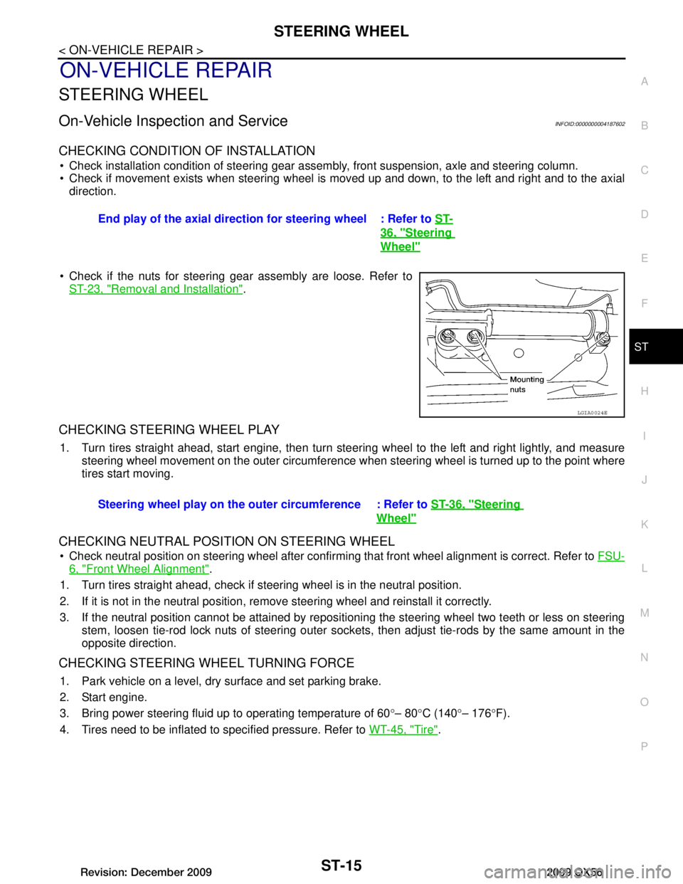
Check if the nuts for steering gear assembly are loose. Refer to ST-23, "Removal and Installation"
.
CHECKING STEERING WHEEL PLAY
1. Turn tires straight ahead, start engine, then turn steer ing wheel to the left and right lightly, and measure
steering wheel movement on the outer circumference when steering wheel is turned up to the point where
tires start moving.
CHECKING NEUTRAL POSITION ON STEERING WHEEL
Check neutral position on steering wheel after confirming that front wheel alignment is correct. Refer to FSU-
6, "Front Wheel Alignment".
1. Turn tires straight ahead, check if st eering wheel is in the neutral position.
2. If it is not in the neutral position, remo ve steering wheel and reinstall it correctly.
3. If the neutral position cannot be attained by repositi oning the steering wheel two teeth or less on steering
stem, loosen tie-rod lock nuts of steering outer socket s, then adjust tie-rods by the same amount in the
opposite direction.
CHECKING STEERING WHEEL TURNING FORCE
1. Park vehicle on a level, dry surface and set parking brake.
2. Start engine.
3. Bring power steering fluid up to operating temperature of 60 °– 80 °C (140 °– 176 °F).
4. Tires need to be inflated to specified pressure. Refer to WT-45, "Tire"
.
End play of the axial direction for steering wheel : Refer to
ST-
36, "Steering
Wheel"
LGIA0024E
Steering wheel play on the outer circumference : Refer to ST-36, "Steering
Wheel"
Revision: December 20092009 QX56
Page 3658 of 4171
TM-10
< FUNCTION DIAGNOSIS >
A/T CONTROL SYSTEM
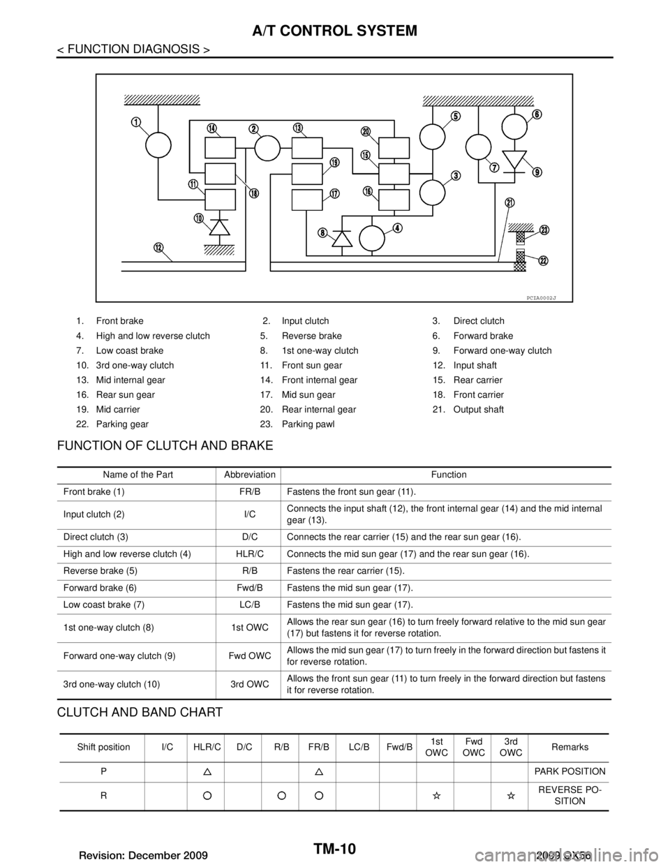
FUNCTION OF CLUTCH AND BRAKE
CLUTCH AND BAND CHART
1. Front brake 2. Input clutch 3. Direct clutch
4. High and low reverse clutch 5. Reverse brake 6. Forward brake
7. Low coast brake 8. 1st one-way clutch 9. Forward one-way clutch
10. 3rd one-way clutch 11. Front sun gear 12. Input shaft
13. Mid internal gear 14. Front internal gear 15. Rear carrier
16. Rear sun gear 17. Mid sun gear 18. Front carrier
19. Mid carrier 20. Rear internal gear 21. Output shaft
22. Parking gear 23. Parking pawl
PCIA0002J
Name of the Part Abbreviation Function
Front brake (1) FR/B Fastens the front sun gear (11).
Input clutch (2) I/C Connects the input shaft (12), the front internal gear (14) and the mid internal
gear (13).
Direct clutch (3) D/C Connects the rear carrier (15) and the rear sun gear (16).
High and low reverse clutch (4) HLR/C Connects the mid sun gear (17) and the rear sun gear (16).
Reverse brake (5) R/B Fastens the rear carrier (15).
Forward brake (6) Fwd/B Fastens the mid sun gear (17).
Low coast brake (7) LC/B Fastens the mid sun gear (17).
1st one-way clutch (8) 1st OWC Allows the rear sun gear (16) to turn freely forward relative to the mid sun gear
(17) but fastens it
for reverse rotation.
Forward one-way clutch (9) Fwd OWC Allows the mid sun gear (17) to turn freely in the forward direction but fastens it
for reverse rotation.
3rd one-way clutch (10) 3rd OWC Allows the front sun gear (11) to turn freely in the forward direction but fastens
it for reverse rotation.
Shift position I/C HLR/C D
/C R/B FR/B LC/B Fwd/B 1st
OWC Fwd
OWC 3rd
OWC Remarks
P PARK POSITION
R REVERSE PO-
SITION
Revision: December 20092009 QX56
Page 3660 of 4171
TM-12
< FUNCTION DIAGNOSIS >
A/T CONTROL SYSTEM
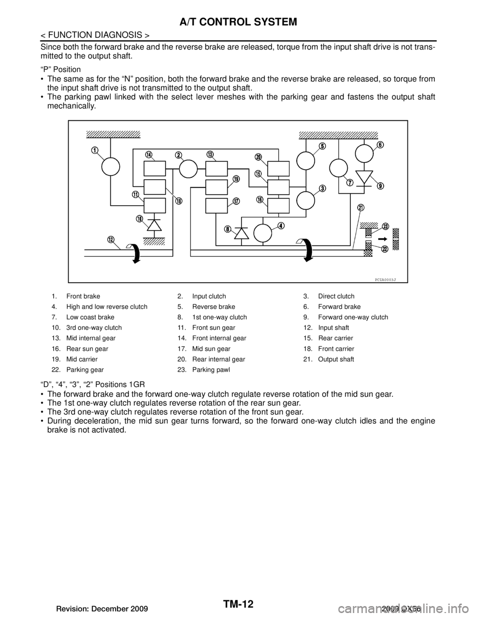
Since both the forward brake and the reverse brake are released, torque from the input shaft drive is not trans-
mitted to the output shaft.
“P” Position
The same as for the “N” position, both the forward br ake and the reverse brake are released, so torque from
the input shaft drive is not transmitted to the output shaft.
The parking pawl linked with the select lever meshes with the parking gear and fastens the output shaft mechanically.
“D”, “4”, “3”, “2” Positions 1GR
The forward brake and the forward one-way clutch regulate reverse rotation of the mid sun gear.
The 1st one-way clutch regulates reverse rotation of the rear sun gear.
The 3rd one-way clutch regulates reverse rotation of the front sun gear.
During deceleration, the mid sun gear turns forward, so the forward one-way clutch idles and the engine
brake is not activated.
1. Front brake 2. Input clutch 3. Direct clutch
4. High and low reverse clutch 5. Reverse brake 6. Forward brake
7. Low coast brake 8. 1st one-way clutch 9. Forward one-way clutch
10. 3rd one-way clutch 11. Front sun gear 12. Input shaft
13. Mid internal gear 14. Front internal gear 15. Rear carrier
16. Rear sun gear 17. Mid sun gear 18. Front carrier
19. Mid carrier 20. Rear internal gear 21. Output shaft
22. Parking gear 23. Parking pawl
PCIA0003J
Revision: December 20092009 QX56
Page 3661 of 4171
A/T CONTROL SYSTEMTM-13
< FUNCTION DIAGNOSIS >
CEF
G H
I
J
K L
M A
B
TM
N
O P
“1” Position 1GR
The front brake fastens the front sun gear.
The forward brake and the forward one-way clutch
regulate reverse rotation of the mid sun gear.
High and low reverse clutch connects the rear sun gear and the mid sun gear.
The low coast brake fastens the mid sun gear.
During deceleration, the low coast brake regulates forward rotation of the mid sun gear and the engine brake
functions.
1. Front brake 2. Input clutch 3. Direct clutch
4. High and low reverse clutch 5. Reverse brake 6. Forward brake
7. Low coast brake 8. 1st one-way clutch 9. Forward one-way clutch
10. 3rd one-way clutch 11. Front sun gear 12. Input shaft
13. Mid internal gear 14. Front internal gear 15. Rear carrier
16. Rear sun gear 17. Mid sun gear 18. Front carrier
19. Mid carrier 20. Rear internal gear 21. Output shaft
22. Parking gear 23. Parking pawl
SCIA1512E
Revision: December 20092009 QX56
Page 3662 of 4171
TM-14
< FUNCTION DIAGNOSIS >
A/T CONTROL SYSTEM
“D”, “4”, “3” Positions 2GR
The forward brake and the forward one-way clutch regulate reverse rotation of the mid sun gear.
The 3rd one-way clutch regulates reverse rotation of the front sun gear.
The direct clutch is coupled and the rear carrier and rear sun gear are connected.
During deceleration, the mid sun gear turns forward, so the forward one-way clutch idles and engine brake is
not activated.
1. Front brake 2. Input clutch 3. Direct clutch
4. High and low reverse clutch 5. Reverse brake 6. Forward brake
7. Low coast brake 8. 1st one-way clutch 9. Forward one-way clutch
10. 3rd one-way clutch 11. Front sun gear 12. Input shaft
13. Mid internal gear 14. Front internal gear 15. Rear carrier
16. Rear sun gear 17. Mid sun gear 18. Front carrier
19. Mid carrier 20. Rear internal gear 21. Output shaft
22. Parking gear 23. Parking pawl
SCIA1513E
Revision: December 20092009 QX56
Page 3663 of 4171
A/T CONTROL SYSTEMTM-15
< FUNCTION DIAGNOSIS >
CEF
G H
I
J
K L
M A
B
TM
N
O P
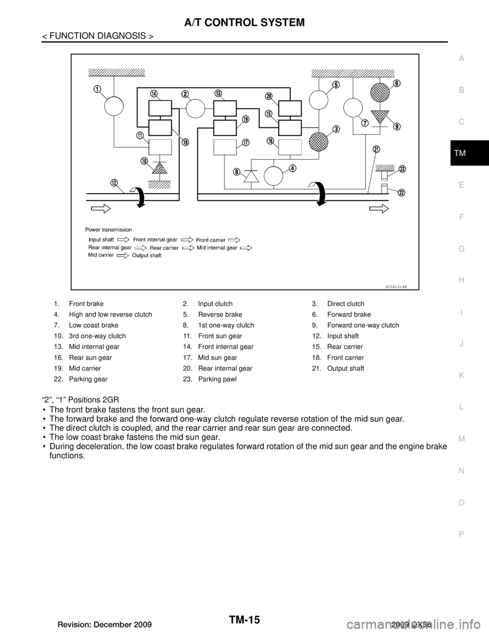
“2”, “1” Positions 2GR
The front brake fastens the front sun gear.
The forward brake and the forward one-way clutch
regulate reverse rotation of the mid sun gear.
The direct clutch is coupled, and the rear carrier and rear sun gear are connected.
The low coast brake fastens the mid sun gear.
During deceleration, the low coast brake regulates forward rotation of the mid sun gear and the engine brake
functions.
1. Front brake 2. Input clutch 3. Direct clutch
4. High and low reverse clutch 5. Reverse brake 6. Forward brake
7. Low coast brake 8. 1st one-way clutch 9. Forward one-way clutch
10. 3rd one-way clutch 11. Front sun gear 12. Input shaft
13. Mid internal gear 14. Front internal gear 15. Rear carrier
16. Rear sun gear 17. Mid sun gear 18. Front carrier
19. Mid carrier 20. Rear internal gear 21. Output shaft
22. Parking gear 23. Parking pawl
SCIA1514E
Revision: December 20092009 QX56
Page 3664 of 4171
TM-16
< FUNCTION DIAGNOSIS >
A/T CONTROL SYSTEM
“D”, “4”, “3” Positions 3GR
The front brake fastens the front sun gear.
The direct clutch is coupled, and the rear carrier and rear sun gear are connected.
The high and low reverse clutch is coupled and the mid sun gear and rear sun gear are connected.
1. Front brake 2. Input clutch 3. Direct clutch
4. High and low reverse clutch 5. Reverse brake 6. Forward brake
7. Low coast brake 8. 1st one-way clutch 9. Forward one-way clutch
10. 3rd one-way clutch 11. Front sun gear 12. Input shaft
13. Mid internal gear 14. Front internal gear 15. Rear carrier
16. Rear sun gear 17. Mid sun gear 18. Front carrier
19. Mid carrier 20. Rear internal gear 21. Output shaft
22. Parking gear 23. Parking pawl
SCIA1515E
Revision: December 20092009 QX56
Page 3665 of 4171
A/T CONTROL SYSTEMTM-17
< FUNCTION DIAGNOSIS >
CEF
G H
I
J
K L
M A
B
TM
N
O P
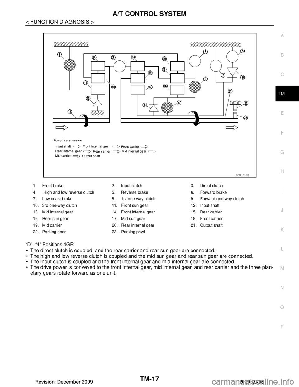
“D”, “4” Positions 4GR
The direct clutch is coupled, and the rear carrier and rear sun gear are connected.
The high and low reverse clutch is coupled and the mid sun gear and rear sun gear are connected.
The input clutch is coupled and the front internal gear and mid internal gear are connected.
The drive power is conveyed to the front internal gear
, mid internal gear, and rear carrier and the three plan-
etary gears rotate forward as one unit.
1. Front brake 2. Input clutch 3. Direct clutch
4. High and low reverse clutch 5. Reverse brake 6. Forward brake
7. Low coast brake 8. 1st one-way clutch 9. Forward one-way clutch
10. 3rd one-way clutch 11. Front sun gear 12. Input shaft
13. Mid internal gear 14. Front internal gear 15. Rear carrier
16. Rear sun gear 17. Mid sun gear 18. Front carrier
19. Mid carrier 20. Rear internal gear 21. Output shaft
22. Parking gear 23. Parking pawl
SCIA1516E
Revision: December 20092009 QX56