2009 INFINITI QX56 parking brake
[x] Cancel search: parking brakePage 3838 of 4171

TM-190
< ON-VEHICLE MAINTENANCE >
ROAD TEST
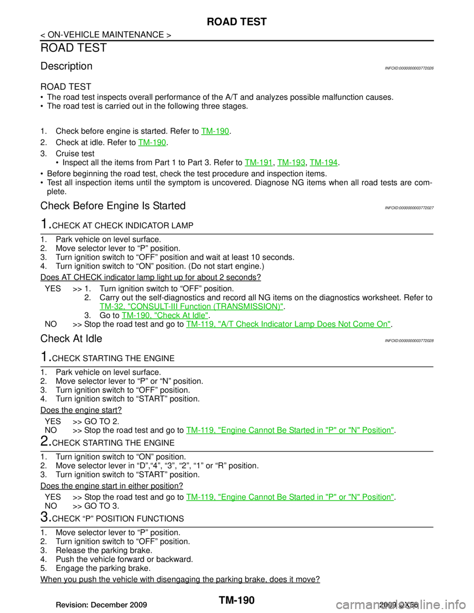
ROAD TEST
DescriptionINFOID:0000000003772026
ROAD TEST
The road test inspects overall performance of the A/T and analyzes possible malfunction causes.
The road test is carried out in the following three stages.
1. Check before engine is started. Refer to TM-190
.
2. Check at idle. Refer to TM-190
.
3. Cruise test Inspect all the items from Part 1 to Part 3. Refer to TM-191
, TM-193, TM-194.
Before beginning the road test, check t he test procedure and inspection items.
Test all inspection items until the symptom is unc overed. Diagnose NG items when all road tests are com-
plete.
Check Before Engine Is StartedINFOID:0000000003772027
1.CHECK AT CHECK INDICATOR LAMP
1. Park vehicle on level surface.
2. Move selector lever to “P” position.
3. Turn ignition switch to “OFF” position and wait at least 10 seconds.
4. Turn ignition switch to “ON” position. (Do not start engine.)
Does AT CHECK indicator lamp light up for about 2 seconds?
YES >> 1. Turn ignition switch to “OFF” position. 2. Carry out the self-diagnostics and record al l NG items on the diagnostics worksheet. Refer to
TM-32, "CONSULT-III Function (TRANSMISSION)"
.
3. Go to TM-190, "Check At Idle"
.
NO >> Stop the road test and go to TM-119, "A/T Check Indicator Lamp Does Not Come On"
.
Check At IdleINFOID:0000000003772028
1.CHECK STARTING THE ENGINE
1. Park vehicle on level surface.
2. Move selector lever to “P” or “N” position.
3. Turn ignition switch to “OFF” position.
4. Turn ignition switch to “START” position.
Does the engine start?
YES >> GO TO 2.
NO >> Stop the road test and go to TM-119, "Engine Cannot Be Started in "P" or "N" Position"
.
2.CHECK STARTING THE ENGINE
1. Turn ignition switch to “ON” position.
2. Move selector lever in “D”,“4”, “3”, “2”, “1” or “R” position.
3. Turn ignition switch to “START” position.
Does the engine start in either position?
YES >> Stop the road test and go to TM-119, "Engine Cannot Be Started in "P" or "N" Position".
NO >> GO TO 3.
3.CHECK “P” POSITION FUNCTIONS
1. Move selector lever to “P” position.
2. Turn ignition switch to “OFF” position.
3. Release the parking brake.
4. Push the vehicle forward or backward.
5. Engage the parking brake.
When you push the vehicle with disengaging the parking brake, does it move?
Revision: December 20092009 QX56
Page 3839 of 4171

ROAD TESTTM-191
< ON-VEHICLE MAINTENANCE >
CEF
G H
I
J
K L
M A
B
TM
N
O P
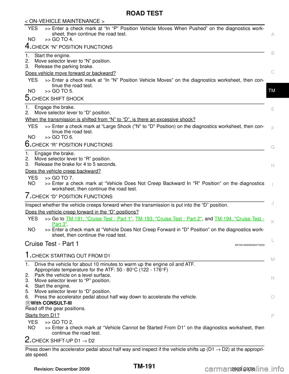
YES >> Enter a check mark at “In “P” Position V ehicle Moves When Pushed” on the diagnostics work-
sheet, then continue the road test.
NO >> GO TO 4.
4.CHECK “N” POSITION FUNCTIONS
1. Start the engine.
2. Move selector lever to “N” position.
3. Release the parking brake.
Does vehicle move forward or backward?
YES >> Enter a check mark at “In “N” Position Ve hicle Moves” on the diagnostics worksheet, then con-
tinue the road test.
NO >> GO TO 5.
5.CHECK SHIFT SHOCK
1. Engage the brake.
2. Move selector lever to “D” position.
When the transmission is shifted from
“N” to “D”, is there an excessive shock?
YES >> Enter a check mark at “Large Shock ("N" to "D" Position) on the diagnostics worksheet, then con-
tinue the road test.
NO >> GO TO 6.
6.CHECK “R” POSITION FUNCTIONS
1. Engage the brake.
2. Move selector lever to “R” position.
3. Release the brake for 4 to 5 seconds.
Does the vehicle creep backward?
YES >> GO TO 7.
NO >> Enter a check mark at “Vehicle Does Not Creep Backward In "R" Position” on the diagnostics worksheet, then continue the road test.
7.CHECK “D” POSITION FUNCTIONS
Inspect whether the vehicle creeps forward when the transmission is put into the “D” position.
Does the vehicle creep forward in the
“D” positions?
YES >> Go to TM-191, "Cruise Test - Part 1", TM-193, "Cruise Test - Part 2", and TM-194, "Cruise Test -
Part 3".
NO >> Enter a check mark at “Vehicle Does Not Creep Forward in "D" Position” on the diagnostics work- sheet, then continue the road test.
Cruise Test - Part 1INFOID:0000000003772029
1.CHECK STARTING OUT FROM D1
1. Drive the vehicle for about 10 minutes to warm up the engine oil and ATF. Appropriate temperature for the ATF: 50 - 80 °C (122 - 176 °F)
2. Park the vehicle on a level surface.
3. Move selector lever to “P” position.
4. Start the engine.
5. Move selector lever to “D” position.
6. Press the accelerator pedal about half way down to accelerate the vehicle.
With CONSULT-III
Read off the gear positions.
Starts from D1?
YES >> GO TO 2.
NO >> Enter a check mark at “Vehicle Cannot be Started From D1” on the diagnostics worksheet, then
continue the road test.
2.CHECK SHIFT-UP D1 → D2
Press down the accelerator pedal about half way and inspect if the vehicle shifts up (D1 → D2) at the appropri-
ate speed.
Revision: December 20092009 QX56
Page 3990 of 4171

WCS
DIAGNOSIS SYSTEM (METER)WCS-13
< FUNCTION DIAGNOSIS >
C
DE
F
G H
I
J
K L
M B A
O P
NOTE:
Some items are not available due to vehicle specification.
*: The monitor will indicate “OFF” even though the brake warnin g lamp is on if either of the following conditions exist.
• The parking brake is engaged
• The brake fluid level is low AT SFT DWN SW [ON/OFF]
XX Displays [ON/O FF] condition of A/T shift-down switch.
DISTANCE [km] or [mile] XXDisplays the value, which is calculated by vehicle speed signal, fuel
gauge and fuel consumption from ECM.
BUZZER [ON/OFF] XX Displays [ON/ OFF] condition of buzzer.
BRAKE SW [ON/OFF] X Indicates [ON/OFF] condition of parking brake switch.
AT-M GEAR [1, 2, 3, 4, 5] XX Indicates [1, 2, 3, 4, 5] condition of A/T manual mode gear position.
P RANGE IND [ON/OFF] XX Indicates [ON/OFF] condition of A/T shift P range indicator.
R RANGE IND [ON/OFF] XX Indicates [ON/OFF] condition of A/T shift R range indicator.
N RANGE IND [ON/OFF] XX Indicates [ON/OFF] condition of A/T shift N range indicator.
D RANGE IND [ON/OFF] XX Indicates [ON/OFF] condition of A/T shift D range indicator.
4 RANGE IND [ON/OFF] XX Indicates [ON/OFF] condition of A/T shift 4 range indicator.
3 RANGE IND [ON/OFF] XX Indicates [ON/OFF] condition of A/T shift 3 range indicator.
2 RANGE IND [ON/OFF] XX Indicates [ON/OFF] condition of A/T shift 2 range indicator.
1 RANGE IND [ON/OFF] XX Indicates [ON/OFF] condition of A/T shift 1range indicator.
CRUISE W/L [ON/OFF] X Indicates [ON/OFF] condition of CRUISE warning lamp.
4WD LOCK SW [ON/OFF] X Indicates [ON/OFF] condition of 4WD lock switch.
4WD LOCK IND [ON/OFF] X Indicates [ON/OFF] condition of 4WD lock indicator.
SEAT BELT W/L [ON/OFF] X Indicates [ON/OFF] condition of seat belt warning lamp.
FR FOG IND [ON/OFF] X This item is not used for this model. “OFF” is always displayed.
RR FOG IND [ON/OFF] X This item is not used for this model. “OFF” is always displayed.
LIGHT IND [ON/OFF] X Indicates [ON/OFF] condition of light indicator.
PNP P SW [ON/OFF] XX Indicates [ON/OFF] condition of park/neutral position P switch.
PNP N SW [ON/OFF] XX Indicates [ON/OFF] condition of park/neutral position N switch.
4WD W/L [ON/OFF] X Indicates [ON/OFF] condition of 4WD warning lamp.
Display item [Unit]
MAIN
SIGNALS SELECTION
FROM MENU Description
Revision: December 20092009 QX56
Page 4005 of 4171

WCS-28
< ECU DIAGNOSIS >
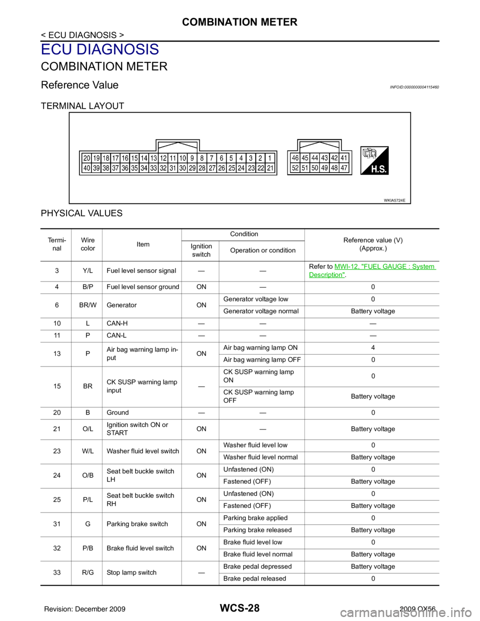
COMBINATION METER
ECU DIAGNOSIS
COMBINATION METER
Reference ValueINFOID:0000000004115460
TERMINAL LAYOUT
PHYSICAL VALUES
WKIA5724E
Te r m i -nal Wire
color Item Condition
Reference value (V)
(Approx.)
Ignition
switch Operation or condition
3 Y/L Fuel level sensor signal — —Refer to MWI-12, "
FUEL GAUGE : System
Description".
4 B/P Fuel level sensor ground ON —0
6 BR/W Generator ONGenerator voltage low
0
Generator voltage normal Battery voltage
10 L CAN-H —— —
11 P C A N - L —— —
13 P Air bag warning lamp in-
put ONAir bag warning lamp ON
4
Air bag warning lamp OFF 0
15 BR CK SUSP warning lamp
input —CK SUSP warning lamp
ON
0
CK SUSP warning lamp
OFF Battery voltage
20 B Ground —— 0
21 O/L Ignition switch ON or
START ON
— Battery voltage
23 W/L Washer fluid level switch ON Washer fluid level low
0
Washer fluid level normal Battery voltage
24 O/B Seat belt buckle switch
LH ONUnfastened (ON)
0
Fastened (OFF) Battery voltage
25 P/L Seat belt buckle switch
RH ONUnfastened (ON)
0
Fastened (OFF) Battery voltage
31 G Parking brake switch ON Parking brake applied
0
Parking brake released Battery voltage
32 P/B Brake fluid level switch ON Brake fluid level low
0
Brake fluid level normal Battery voltage
33 R/G Stop lamp switch —Brake pedal depressed
Battery voltage
Brake pedal released 0
Revision: December 20092009 QX56