2009 INFINITI QX56 fuel pump
[x] Cancel search: fuel pumpPage 1846 of 4171
COMPRESSION PRESSUREEM-23
< ON-VEHICLE MAINTENANCE >
C
DE
F
G H
I
J
K L
M A
EM
NP
O
COMPRESSION PRESSURE
Checking Compression PressureINFOID:0000000005885870
1. Warm up the engine thoroughly. Then stop the engine.
2. Release the fuel pressure. Refer to EC-487, "
Fuel Pressure Check".
CAUTION:
If CONSULT-III is not used to release fuel pressure leave the fuel pump fuse disconnected until
step 7.
3. Remove the spark plug from each cylinder. Refer to EM-16, "
Removal and Installation".
4. Connect the engine tachometer (not required in use of CONSULT-III).
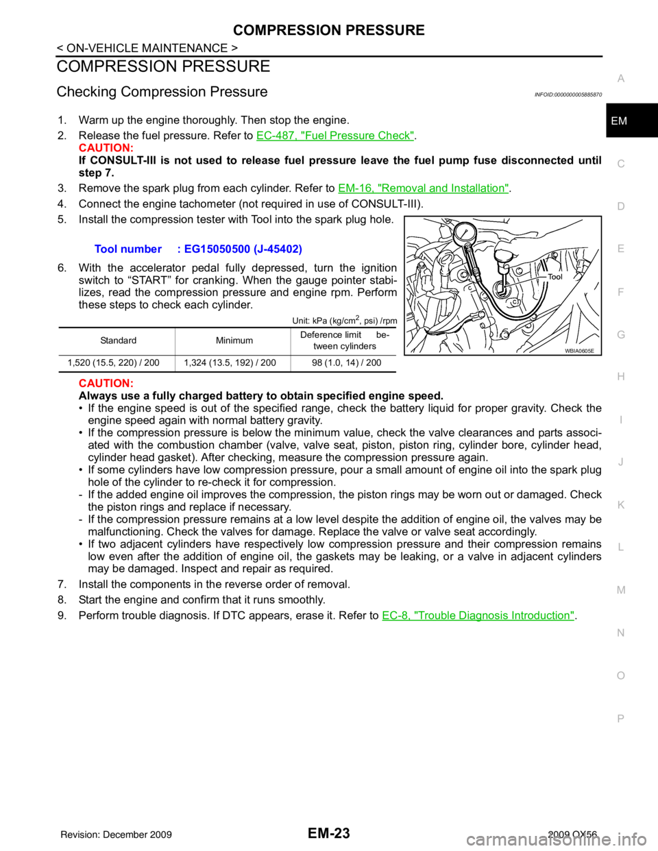
5. Install the compression tester with Tool into the spark plug hole.
6. With the accelerator pedal fully depressed, turn the ignition switch to “START” for cranking. When the gauge pointer stabi-
lizes, read the compression pressure and engine rpm. Perform
these steps to check each cylinder.
Unit: kPa (kg/cm2, psi) /rpm
CAUTION:
Always use a fully charged battery to obtain specified engine speed.
• If the engine speed is out of the specified range, check the battery liquid for proper gravity. Check the engine speed again with normal battery gravity.
• If the compression pressure is below the minimum value, check the valve clearances and parts associ-
ated with the combustion chamber (valve, valve seat , piston, piston ring, cylinder bore, cylinder head,
cylinder head gasket). After checking, measure the compression pressure again.
• If some cylinders have low compression pressure, pour a small amount of engine oil into the spark plug hole of the cylinder to re-check it for compression.
- If the added engine oil improves the compression, t he piston rings may be worn out or damaged. Check
the piston rings and replace if necessary.
- If the compression pressure remains at a low level despite the addition of engine oil, the valves may be malfunctioning. Check the valves for damage. Replace the valve or valve seat accordingly.
• If two adjacent cylinders have respectively low compression pressure and their compression remains low even after the addition of engine oil, the gaskets may be leaking, or a valve in adjacent cylinders
may be damaged. Inspect and repair as required.
7. Install the components in the reverse order of removal.
8. Start the engine and confirm that it runs smoothly.
9. Perform trouble diagnosis. If DTC appears, erase it. Refer to EC-8, "
Trouble Diagnosis Introduction".
Tool number : EG15050500 (J-45402)
Standard
MinimumDeference limit be-
tween cylinders
1,520 (15.5, 220) / 200 1,324 (13.5, 192) / 200 98 (1.0, 14) / 200WBIA0605E
Revision: December 20092009 QX56
Page 1891 of 4171
EM-68
< ON-VEHICLE REPAIR >
CYLINDER HEAD
CYLINDER HEAD
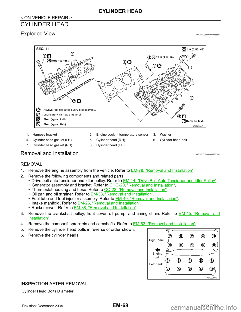
Exploded ViewINFOID:0000000005885894
Removal and InstallationINFOID:0000000005885895
REMOVAL
1. Remove the engine assembly from the vehicle. Refer to EM-78, "Removal and Installation".
2. Remove the following components and related parts: • Drive belt auto tensioner and idler pulley. Refer to EM-14, "
Drive Belt Auto Tensioner and Idler Pulley".
• Generator assembly and bracket. Refer to CHG-20, "
Removal and Installation".
• Thermostat housing and hose. Refer to CO-22, "
Removal and Installation".
• Oil pan and oil strainer. Refer to EM-33, "
Removal and Installation".
• Fuel tube and fuel injector assembly. Refer to EM-40, "
Removal and Installation".
• Intake manifold. Refer to EM-26, "
Removal and Installation".
• Rocker cover. Refer to EM-38, "
Removal and Installation".
3. Remove the crankshaft pulley, front cover, oil pump, and timing chain. Refer to EM-45, "
Removal and
Installation".
4. Remove the camshaft sprockets and camshafts. Refer to EM-53, "
Removal and Installation".
5. Remove the cylinder head bolts in reverse of order shown.
6. Remove the cylinder heads.
INSPECTION AFTER REMOVAL
Cylinder Head Bolts Diameter
1. Harness bracket 2. Engine coolant temperature sensor 3. Washer
4. Cylinder head gasket (LH) 5. Cylinder head (RH) 6. Cylinder head bolt
7. Cylinder head gasket (RH) 8. Cylinder head (LH)
KBIA2528E
PBIC0068E
Revision: December 20092009 QX56
Page 1902 of 4171
ENGINE ASSEMBLYEM-79
< REMOVAL AND INSTALLATION >
C
DE
F
G H
I
J
K L
M A
EM
NP
O
1. Release the fuel pressure. Refer to
EC-487, "Fuel Pressure Check".
2. Drain the engine coolant. Refer to CO-11, "
Changing Engine Coolant".
3. Drain the engine oil. Refer to LU-9, "
Changing Engine Oil".
4. Disconnect the battery negative and positive terminal. Refer to PG-76, "
Removal and Installation".
5. Remove the engine hood. Refer to DLK-230, "
Removal and Installation of Hood Assembly".
6. Remove the cowl extension. Refer to EXT-18, "
Removal and Installation".
7. Remove the air duct and air cleaner case assembly. Refer to EM-25, "
Removal and Installation".
8. Remove the radiator assembly and hoses. Refer to CO-15, "
Removal and Installation".
NOTE:
To prevent possible A/T fluid drain from transmissi on opening, use appropriate cap to close off transmis-
sion opening during operation.
9. Remove the drive belt. Refer to EM-13, "
Removal and Installation".
10. Remove the fan blade. Refer to CO-18, "
Removal and Installation (Crankshaft Driven Type)".
11. Disconnect the engine room harness from the fuse box and set it aside.
12. Disconnect the ECM.
13. Disconnect the engine room harness from the engine side and set it aside.
14. Disconnect the engine harness grounds.
15. Disconnect the power steering reservoir t ank from the engine and move it aside.
16. Disconnect the power steering oil pump from the engine. Move it aside and secure it using suitable wire or rope. Refer to ST-26, "
Removal and Installation"
17. Remove the A/C compressor bolts and set the compressor aside. Refer to HA-31, "Removal and Installa-
tion for Compressor" (ATC).
18. Disconnect the brake booster vacuum hose.
19. Disconnect the EVAP line.
20. Disconnect the fuel hose at the engine side connection. Refer to EM-40, "
Removal and Installation".
21. Disconnect the heater hoses at the cowl, and in stall plugs to avoid leakage of engine coolant.
22. Remove the A/T oil level indicator and indicator tube upper bolts.
23. Remove the front final drive assembly (4WD only). Refer to DLN-215, "
Removal and Installation".
24. Remove the exhaust manifolds. Refer to EM-30, "
Removal and Installation".
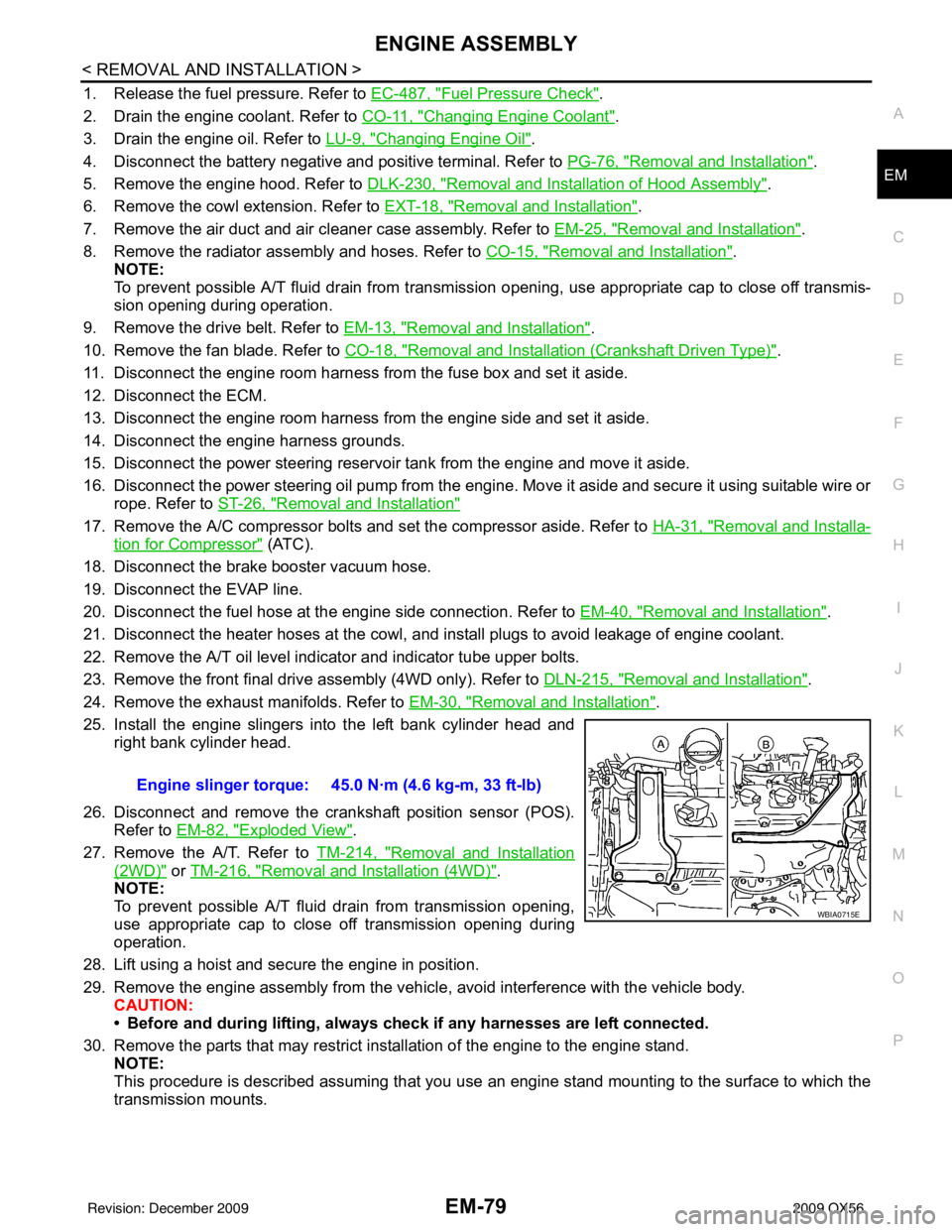
25. Install the engine slingers into the left bank cylinder head and right bank cylinder head.
26. Disconnect and remove the crankshaft position sensor (POS). Refer to EM-82, "
Exploded View".
27. Remove the A/T. Refer to TM-214, "
Removal and Installation
(2WD)" or TM-216, "Removal and Installation (4WD)".
NOTE:
To prevent possible A/T fluid drain from transmission opening,
use appropriate cap to close off transmission opening during
operation.
28. Lift using a hoist and secure the engine in position.
29. Remove the engine assembly from the vehicl e, avoid interference with the vehicle body.
CAUTION:
• Before and during lifting, always check if any harnesses are left connected.
30. Remove the parts that may restrict installation of the engine to the engine stand. NOTE:
This procedure is described assuming that you use an engine stand mounting to the surface to which the
transmission mounts. Engine slinger torque: 45.0 N·m (4.6 kg-m, 33 ft-lb)
WBIA0715E
Revision: December 20092009 QX56
Page 2072 of 4171

EXL-124
< ECU DIAGNOSIS >
IPDM E/R (INTELLIGENT POWER DISTRIBUTION MODULE ENGINE ROOM)
Te r m i n a lWire
color Signal name Signal
input/
output Measuring condition
Reference value(Approx.)
Igni-
tion
switch Operation or condition
1 B/Y Battery power supply Input OFF —Battery voltage
2 R Battery power supply Input OFF —Battery voltage
3 BR ECM relay Output —Ignition switch ON or START
Battery voltage
Ignition switch OFF or ACC 0V
4 W/L ECM relay Output —Ignition switch ON or START
Battery voltage
Ignition switch OFF or ACC 0V
6L Throttle control motor
relay Output —Ignition switch ON or START
Battery voltage
Ignition switch OFF or ACC 0V
7 W/B ECM relay control Input — Ignition switch ON or START
0V
Ignition switch OFF or ACC Battery voltage
8 R/B Fuse 54 Output —Ignition switch ON or START
Battery voltage
Ignition switch OFF or ACC 0V
10 G Fuse 45 Output ONDaytime light system active
0V
Daytime light system inactive Battery voltage
11 Y/B A/C compressor Output ON or
START A/C switch ON or defrost A/C
switch
Battery voltage
A/C switch OFF or defrost A/C
switch 0V
12 L/W Ignition switch sup-
plied power Input —OFF or ACC
0V
ON or START Battery voltage
13 B/Y Fuel pump relay Output — Ignition switch ON or START
Battery voltage
Ignition switch OFF or ACC 0V
14 Y/R Fuse 49 Output —Ignition switch ON or START
Battery voltage
Ignition switch OFF or ACC 0V
15 LG/B Fuse 50 (VDC) Output — Ignition switch ON or START
Battery voltage
Ignition switch OFF or ACC 0V
15 GR Fuse 50 (ABS) Output — Ignition switch ON or START
Battery voltage
Ignition switch OFF or ACC 0V
16 G Fuse 51 Output —Ignition switch ON or START
Battery voltage
Ignition switch OFF or ACC 0V
17 W Fuse 55 Output —Ignition switch ON or START
Battery voltage
Ignition switch OFF or ACC 0V
19 W/R Starter motor Output START—Battery voltage
21 BR Ignition switch sup-
plied power
Input —OFF or ACC
0V
START Battery voltage
22 G Battery power supply Output OFF —Battery voltage
23 GR/W Door mirror defogger
output signal Output —When rear defogger switch is
ON
Battery voltage
When raker defogger switch is
OFF 0V
Revision: December 20092009 QX56
Page 2074 of 4171

EXL-126
< ECU DIAGNOSIS >
IPDM E/R (INTELLIGENT POWER DISTRIBUTION MODULE ENGINE ROOM)
41 Y/B Hood switch Input —Hood closed OFF
0V
Hood open ON Battery voltage
42 GR Oil pressure switch Input — Engine running
Battery voltage
Engine stopped 0V
43 L/Y Wiper auto stop signal Input ON or
START Wiper switch OFF, LO, INT Battery voltage
44 BR Daytime light relay
control Input ONDaytime light system active
0V
Daytime light system inactive Battery voltage
45 G/W Horn relay control Input ON When door locks are operated
using keyfob or Intelligent Key
(OFF
→ ON)* Battery voltage
→ 0V
46 GR Fuel pump relay con-
trol
Input —Ignition switch ON or START
0V
Ignition switch OFF or ACC Battery voltage
47 O Throttle control motor
relay control
Input —Ignition switch ON or START
0V
Ignition switch OFF or ACC Battery voltage
48 B/R Starter relay (inhibit
switch) InputON or
START Selector lever in "P" or "N"
0V
Selector lever any other posi-
tion Battery voltage
49 R/L Trailer tow relay Output ON Lighting
switch must
be in the 1st
positionOFF
0V
ON Battery voltage
50 W/R Front fog lamp (LH) Output ON or
START Lighting
switch must
be in the 2nd
position
(LOW beam
is ON) and
the front fog
lamp switch OFF
0V
ON Battery voltage
51 W/R Front fog lamp (RH) Output ON or
START Lighting
switch must
be in the 2nd
position
(LOW beam
is ON) and
the front fog
lamp switch OFF
0V
ON Battery voltage
52 L LH low beam head-
lamp Output — Lighting switch in 2nd position Battery voltage
54 R/Y RH low beam head-
lamp Output — Lighting switch in 2nd position Battery voltage
55 G LH high beam head-
lamp Output —Lighting switch in 2nd position
and placed in HIGH or PASS
position Battery voltage
56 L/W RH high beam head-
lamp Output —Lighting switch in 2nd position
and placed in HIGH or PASS
position Battery voltage
57 R/L Parking, license, and
tail lamp
Output ONLighting
swi
t
ch 1st po-
sition OFF
0V
ON Battery voltage
Te r m i n a l
Wire
color Signal name Signal
input/
output Measuring condition
Reference value(Approx.)
Igni-
tion
switch Operation or condition
Revision: December 20092009 QX56
Page 2154 of 4171

FL-1
ENGINE
C
DE
F
G H
I
J
K L
M
SECTION FL
A
FL
N
O P
CONTENTS
FUEL SYSTEM
PRECAUTION ....... ........................................2
PRECAUTIONS .............................................. .....2
Precaution for Supplemental Restraint System
(SRS) "AIR BAG" and "SEAT BELT PRE-TEN-
SIONER" ............................................................. ......
2
Precaution Necessary for Steering Wheel Rota-
tion After Battery Disconnect ............................... ......
2
FUEL SYSTEM ....................................................4
General Precaution ............................................. ......4
PREPARATION ............................................5
PREPARATION .............................................. .....5
Special Service Tool ........................................... ......5
Commercial Service Tool ..........................................5
BASIC INSPECTION ....................................6
FUEL SYSTEM ............................................... .....6
Checking Fuel Line ............................................. ......6
REMOVAL AND INSTALLATION ................7
FUEL LEVEL SENSOR UNIT, FUEL FILTER
AND FUEL PUMP ASSEMBLY .........................
7
Removal and Installation ..................................... .....7
FUEL TANK ......................................................11
Removal and Installation ..................................... ....11
DISASSEMBLY AND ASSEMBLY ..............16
FUEL LEVEL SENSOR UNIT, FUEL FILTER
AND FUEL PUMP ASSEMBLY ........................
16
Disassembly and Assembly ................................. ....16
SERVICE DATA AND SPECIFICATIONS
(SDS) ............... .......................................... ...
17
SERVICE DATA AND SPECIFICATIONS
(SDS) .................................................................
17
Standard and Limit .............................................. ....17
Revision: December 20092009 QX56
Page 2160 of 4171
FUEL LEVEL SENSOR UNIT, FUEL FILTER AND FUEL PUMP ASSEMBLYFL-7
< REMOVAL AND INSTALLATION >
C
DE
F
G H
I
J
K L
M A
FL
NP
O
REMOVAL AND INSTALLATION
FUEL LEVEL SENSOR UNIT, FUEL FI
LTER AND FUEL PUMP ASSEMBLY
Removal and InstallationINFOID:0000000003771773
REMOVAL
WARNING:
Follow the “General Precautions” before working on the fuel system. Refer to FL-4, "
General Precau-
tion".
1. Remove the fuel filler cap to release the pressure from inside the fuel tank.
2. Release the fuel pressure from the fuel lines. Refer to EC-487, "
Fuel Pressure Check".
3. Remove the second row seat and the third row LH seat. Refer to SE-55, "
Removal and Installation" (sec-
ond row), SE-58, "
LH Side Seat" (third row).
4. Disconnect the battery negative terminal. Refer to PG-76, "
Removal and Installation".
5. Remove the second and third row rear seat belt buckles mounted on the floor. Refer to SB-7, "
Removal
and Installation of Second Row Seat Belt", SB-9, "Removal and Installation of Third Row Seat Belt".
6. Remove the LH center pillar trim, the LH rear trim panel, and the LH rear side door kick plate and weather stripping. Refer to INT-14, "
Removal and Installation".
7. Remove the second row rear center console and base, if equipped. Refer to IP-21, "
Removal and Installa-
tion".
8. Reposition the floor carpet out of the way to access the inspection hole cover, located under the center LH rear seat.
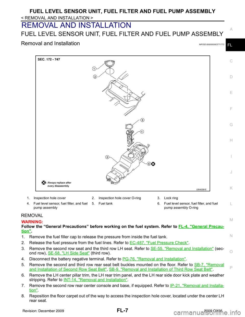
1. Inspection hole cover 2. Inspection hole cover O-ring 3. Lock ring
4. Fuel level sensor, fuel filter, and fuel pump assembly 5. Fuel tank
6. Fuel level sensor, fuel filter, and fuel
pump assembly O-ring
LBIA0381E
Revision: December 20092009 QX56
Page 2161 of 4171
FL-8
< REMOVAL AND INSTALLATION >
FUEL LEVEL SENSOR UNIT, FUEL FILTER AND FUEL PUMP ASSEMBLY
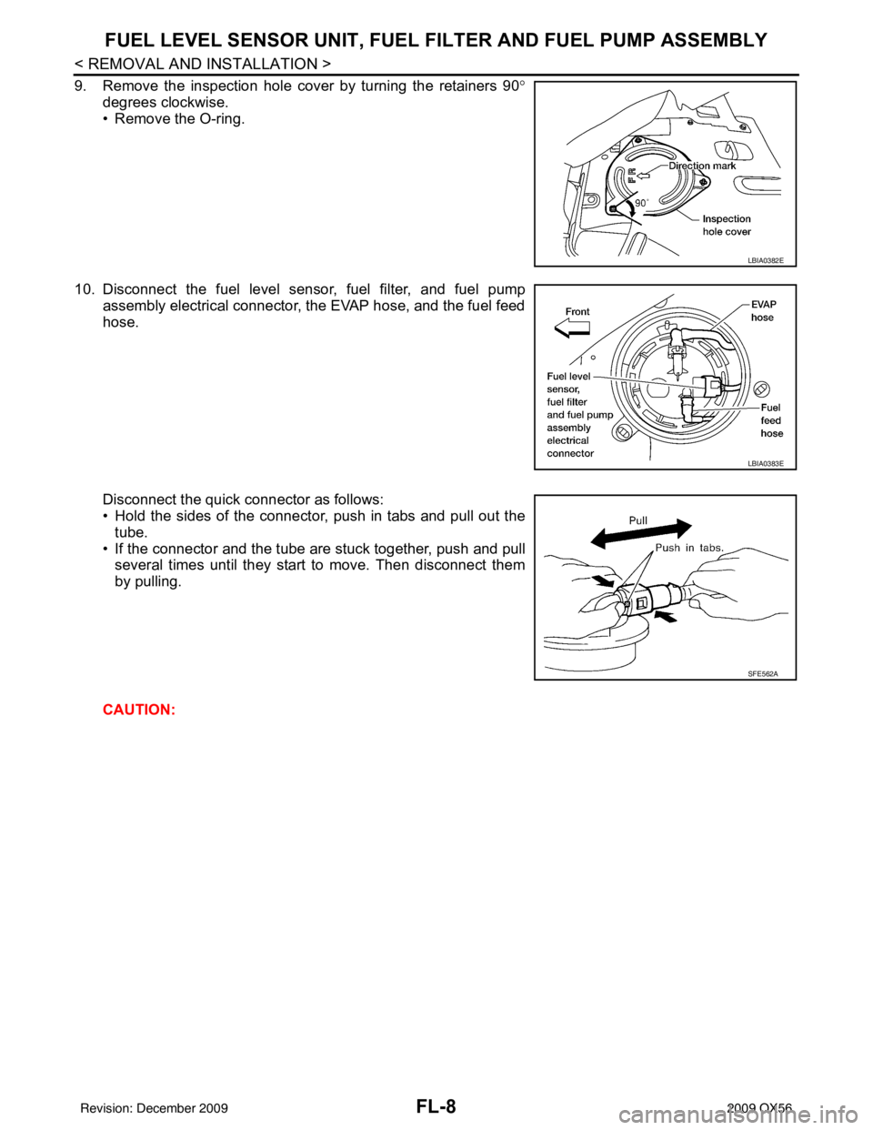
9. Remove the inspection hole cover by turning the retainers 90 °
degrees clockwise.
• Remove the O-ring.
10. Disconnect the fuel level sensor, fuel filter, and fuel pump assembly electrical connector, the EVAP hose, and the fuel feed
hose.
Disconnect the quick connector as follows:
• Hold the sides of the connector, push in tabs and pull out the
tube.
• If the connector and the tube are stuck together, push and pull several times until they start to move. Then disconnect them
by pulling.
CAUTION:
LBIA0382E
LBIA0383E
SFE562A
Revision: December 20092009 QX56