2009 INFINITI QX56 fuel pump
[x] Cancel search: fuel pumpPage 3640 of 4171

S CONNECTOR CIRCUITSTR-11
< COMPONENT DIAGNOSIS >
C
DE
F
G H
I
J
K L
M A
STR
NP
O
S CONNECTOR CIRCUIT
DescriptionINFOID:0000000003771794
Terminal "1" (S) is the power supply for the starter mo
tor magnetic switch. Terminal 1 is supplied with power
when the ignition switch is turned to the START position while the selector lever is in the P or N position.
Diagnosis ProcedureINFOID:0000000003771795
CAUTION:
Perform diagnosis under the cond ition that engine cannot start by the following procedure.
1. Remove fuel pump fuse.
2. Crank or start the engine (where possi ble) until the fuel pressure is released.
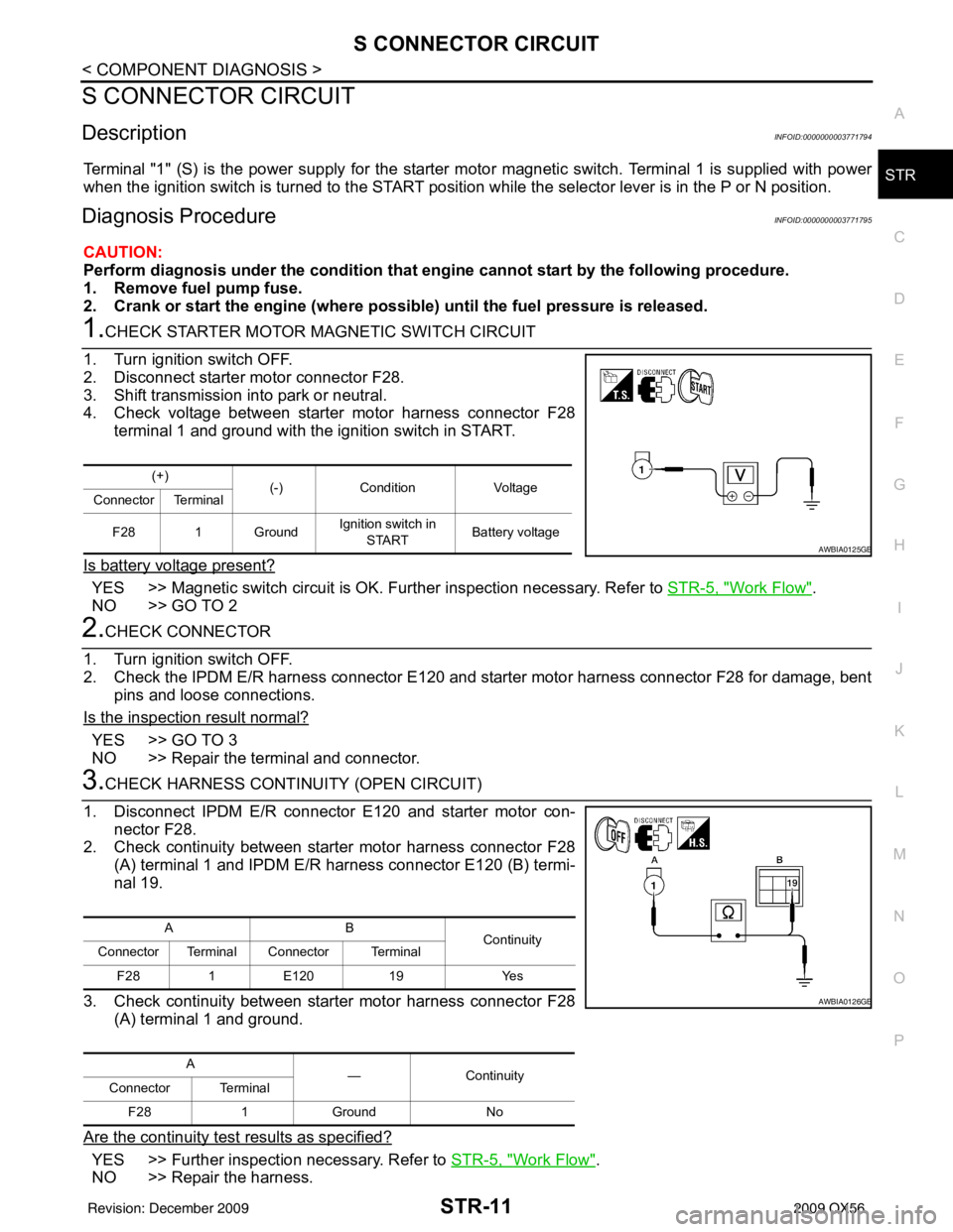
1.CHECK STARTER MOTOR MAGNETIC SWITCH CIRCUIT
1. Turn ignition switch OFF.
2. Disconnect starter motor connector F28.
3. Shift transmission into park or neutral.
4. Check voltage between starter motor harness connector F28 terminal 1 and ground with the ignition switch in START.
Is battery voltage present?
YES >> Magnetic switch circuit is OK. Further inspection necessary. Refer to STR-5, "Work Flow".
NO >> GO TO 2
2.CHECK CONNECTOR
1. Turn ignition switch OFF.
2. Check the IPDM E/R harness connector E120 and starter motor harness connector F28 for damage, bent pins and loose connections.
Is the inspection result normal?
YES >> GO TO 3
NO >> Repair the terminal and connector.
3.CHECK HARNESS CONTI NUITY (OPEN CIRCUIT)
1. Disconnect IPDM E/R connector E120 and starter motor con- nector F28.
2. Check continuity between starter motor harness connector F28 (A) terminal 1 and IPDM E/R harness connector E120 (B) termi-
nal 19.
3. Check continuity between starter motor harness connector F28 (A) terminal 1 and ground.
Are the continuity test results as specified?
YES >> Further inspection necessary. Refer to STR-5, "Work Flow".
NO >> Repair the harness.
(+) (-)Condition Voltage
Connector Terminal
F28 1 Ground Ignition switch in
START Battery voltage
AWBIA0125GB
AB
Continuity
Connector Terminal Connector Terminal
F28 1E120 19 Yes
A —Con tin uit y
Connector Terminal
F28 1Ground No
AWBIA0126GB
Revision: December 20092009 QX56
Page 3674 of 4171

TM-26
< FUNCTION DIAGNOSIS >
A/T CONTROL SYSTEM
When shifting from the lock-up released state to the lock-up applied state, the current output to the torque con-
verter clutch solenoid is controlled with the TCM. In th is way, when shifting to the lock-up applied state, the
torque converter clutch is temporarily set to the half-clutched state to reduce the shock.
Half-clutched State
The current output from the TCM to the torque converte r clutch solenoid is varied to gradually increase the
torque converter clutch solenoid pressure.
In this way, the lock-up apply pressure gradually rises and while the torque converter clutch piston is put into
half-clutched status, the torque converter clutch pi ston operating pressure is increased and the coupling is
completed smoothly.
Slip Lock-up Control
In the slip region, the torque converter clutch solenoid current is controlled with the TCM to put it into the
half-clutched state. This absorbs the engine tor que fluctuation and lock-up operates from low speed.
This raises the fuel efficiency for 4GR and 5GR at both low speed and when the accelerator has a low
degree of opening.
Engine Brake ControlINFOID:0000000003771814
The forward one-way clutch transmits the drive force from the engine to the rear wheels. But the reverse
drive from the rear wheels is not transmitted to the engine because the one-way clutch is idling.
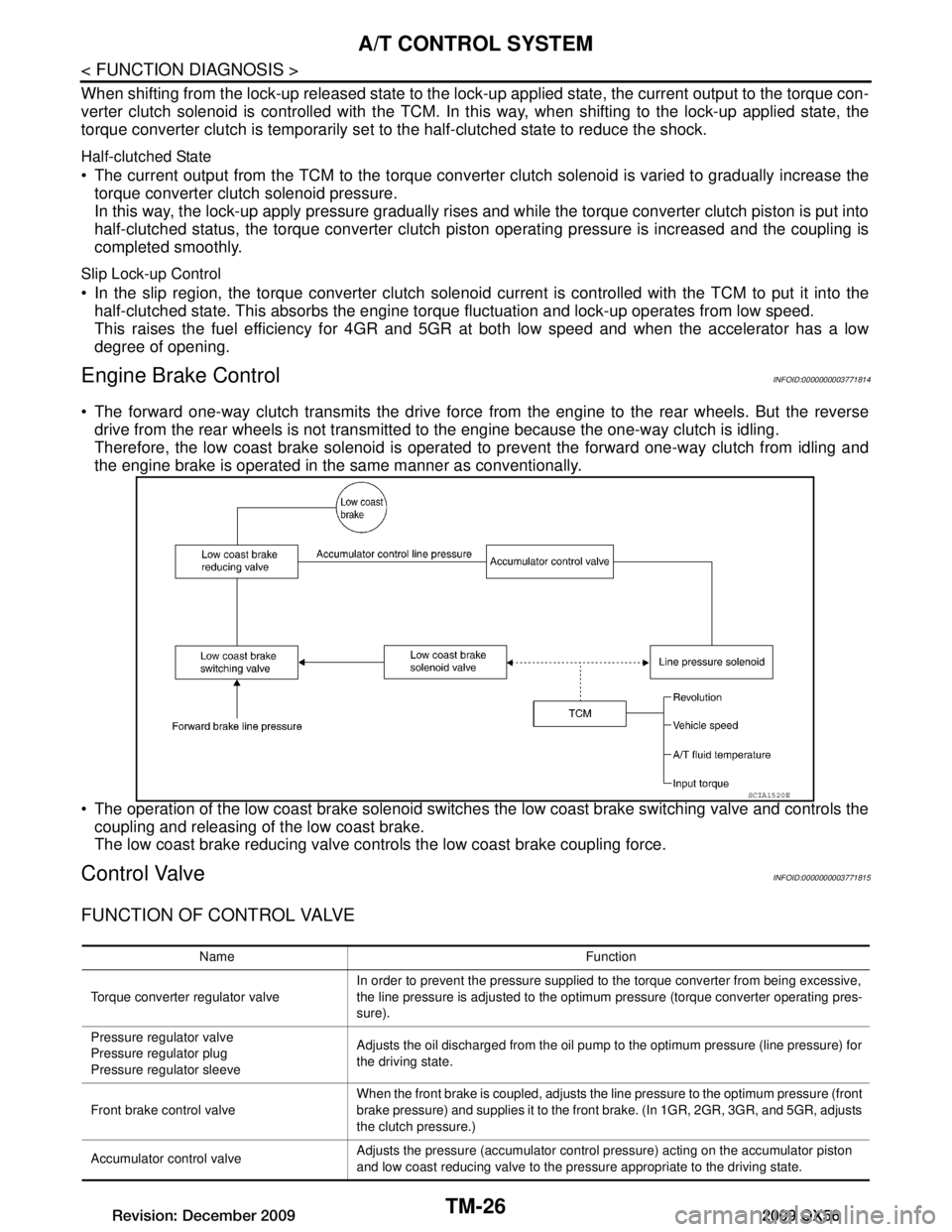
Therefore, the low coast brake solenoid is operated to prevent the forward one-way clutch from idling and
the engine brake is operated in the same manner as conventionally.
The operation of the low coast brake solenoid switches the low coast brake switching valve and controls the
coupling and releasing of the low coast brake.
The low coast brake reducing valve contro ls the low coast brake coupling force.
Control ValveINFOID:0000000003771815
FUNCTION OF CONTROL VALVE
SCIA1520E
Name Function
Torque converter regulator valve In order to prevent the pressure supplied to the torque converter from being excessive,
the line pressure is adjusted to the optimum pressure (torque converter operating pres-
sure).
Pressure regu lator valve
Pressure regulator plug
Pressure regu lator sleeve Adjusts the oil discharged from the oil pump to the optimum pressure (line pressure) for
the driving state.
Front brake control valve When the front brake is coupled, adjusts the line pressure to the optimum pressure (front
brake pressure) and supplies it to the front brake. (In 1GR, 2GR, 3GR, and 5GR, adjusts
the clutch pressure.)
Accumulator control valve Adjusts the pressure (accumulator control pressure) acting on the accumulator piston
and low coast reducing valve to the pressure appropriate to the driving state.
Revision: December 20092009 QX56
Page 4144 of 4171

IPDM E/R (INTELLIGENT POWER DISTRIBUTION MODULE ENGINE ROOM)
WW-57
< ECU DIAGNOSIS >
C
D E
F
G H
I
J
K
M A
B
WW
N
O P
Te r m i n a l Wire
color Signal name Signal
input/
output Measuring condition
Reference value(Approx.)
Igni-
tion
switch Operation or condition
1 B/Y Battery power supply Input OFF —Battery voltage
2 R Battery power supply Input OFF —Battery voltage
3BRECM relay Output— Ignition switch ON or START
Battery voltage
Ignition switch OFF or ACC 0V
4W/LECM relay Output— Ignition switch ON or START
Battery voltage
Ignition switch OFF or ACC 0V
6L Throttle control motor
relay Output —Ignition switch ON or START
Battery voltage
Ignition switch OFF or ACC 0V
7 W/B ECM relay control Input — Ignition switch ON or START
0V
Ignition switch OFF or ACC Battery voltage
8 R/B Fuse 54 Output —Ignition switch ON or START
Battery voltage
Ignition switch OFF or ACC 0V
10 G Fuse 45 Output ONDaytime light system active
0V
Daytime light system inactive Battery voltage
11 Y/B A/C compressor Output ON or
START A/C switch ON or defrost A/C
switch
Battery voltage
A/C switch OFF or defrost A/C
switch 0V
12 L/W Ignition switch sup-
plied power Input —OFF or ACC
0V
ON or START Battery voltage
13 B/Y Fuel pump relay Output — Ignition switch ON or START
Battery voltage
Ignition switch OFF or ACC 0V
14 Y/R Fuse 49 Output —Ignition switch ON or START
Battery voltage
Ignition switch OFF or ACC 0V
15 LG/B Fuse 50 (VDC) Output — Ignition switch ON or START
Battery voltage
Ignition switch OFF or ACC 0V
15 GR Fuse 50 (ABS) Output — Ignition switch ON or START
Battery voltage
Ignition switch OFF or ACC 0V
16 G Fuse 51 Output —Ignition switch ON or START
Battery voltage
Ignition switch OFF or ACC 0V
17 W Fuse 55 Output —Ignition switch ON or START
Battery voltage
Ignition switch OFF or ACC 0V
19 W/R Starter motor Output START—Battery voltage
21 BR Ignition switch sup-
plied power
Input —OFF or ACC
0V
START Battery voltage
22 G Battery power supply Output OFF —Battery voltage
23 GR/W Door mirror defogger
output signal Output —When rear defogger switch is
ON
Battery voltage
When raker defogger switch is
OFF 0V
Revision: December 20092009 QX56
Page 4146 of 4171

IPDM E/R (INTELLIGENT POWER DISTRIBUTION MODULE ENGINE ROOM)
WW-59
< ECU DIAGNOSIS >
C
D E
F
G H
I
J
K
M A
B
WW
N
O P
41 Y/B Hood switch Input —Hood closed OFF
0V
Hood open ON Battery voltage
42 GR Oil pressure switch Input — Engine running
Battery voltage
Engine stopped 0V
43 L/Y Wiper auto stop signal Input ON or
START Wiper switch OFF, LO, INT Battery voltage
44 BR Daytime light relay
control Input ONDaytime light system active
0V
Daytime light system inactive Battery voltage
45 G/W Horn relay control Input ON When door locks are operated
using keyfob or Intelligent Key
(OFF
→ ON)* Battery voltage
→ 0V
46 GR Fuel pump relay con-
trol
Input —Ignition switch ON or START
0V
Ignition switch OFF or ACC Battery voltage
47 O Throttle control motor
relay control
Input —Ignition switch ON or START
0V
Ignition switch OFF or ACC Battery voltage
48 B/R Starter relay (inhibit
switch) InputON or
START Selector lever in "P" or "N"
0V
Selector lever any other posi-
tion Battery voltage
49 R/L Trailer tow relay Output ON Lighting
switch must
be in the 1st
positionOFF
0V
ON Battery voltage
50 W/R Front fog lamp (LH) Output ON or
START Lighting
switch must
be in the 2nd
position
(LOW beam
is ON) and
the front fog
lamp switch OFF
0V
ON Battery voltage
51 W/R Front fog lamp (RH) Output ON or
START Lighting
switch must
be in the 2nd
position
(LOW beam
is ON) and
the front fog
lamp switch OFF
0V
ON Battery voltage
52 L LH low beam head-
lamp Output — Lighting switch in 2nd position Battery voltage
54 R/Y RH low beam head-
lamp Output — Lighting switch in 2nd position Battery voltage
55 G LH high beam head-
lamp Output —Lighting switch in 2nd position
and placed in HIGH or PASS
position Battery voltage
56 L/W RH high beam head-
lamp Output —Lighting switch in 2nd position
and placed in HIGH or PASS
position Battery voltage
57 R/L Parking, license, and
tail lamp
Output ONLighting
swi
t
ch 1st po-
sition OFF
0V
ON Battery voltage
Te r m i n a l
Wire
color Signal name Signal
input/
output Measuring condition
Reference value(Approx.)
Igni-
tion
switch Operation or condition
Revision: December 20092009 QX56