2009 INFINITI QX56 fuel pump
[x] Cancel search: fuel pumpPage 2737 of 4171
MWI
METER SYSTEMMWI-15
< FUNCTION DIAGNOSIS >
C
DE
F
G H
I
J
K L
M B A
O P
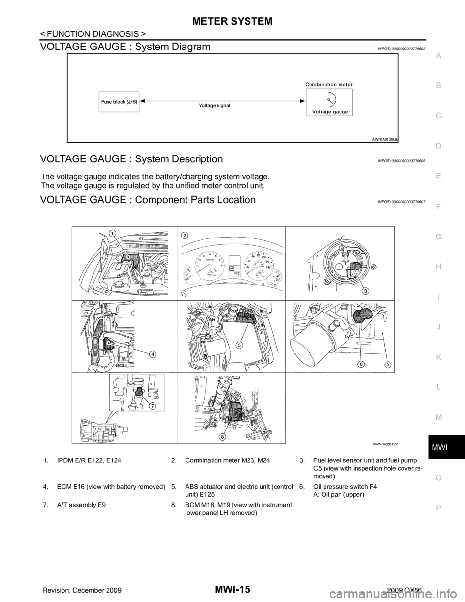
VOLTAGE GAUGE : System DiagramINFOID:0000000003776605
VOLTAGE GAUGE : System DescriptionINFOID:0000000003776606
The voltage gauge indicates the battery/charging system voltage.
The voltage gauge is regulated by the unified meter control unit.
VOLTAGE GAUGE : Component Parts LocationINFOID:0000000003776607
AWNIA0106GB
1. IPDM E/R E122, E124 2. Combination meter M23, M24 3. Fuel level sensor unit and fuel pump
C5 (view with inspection hole cover re-
moved)
4. ECM E16 (view with battery removed) 5. ABS actuator and electric unit (control unit) E1256. Oil pressure switch F4
A: Oil pan (upper)
7. A/T assembly F9 8. BCM M18, M19 (view with instrument
lower panel LH removed)
AWNIA0201ZZ
Revision: December 20092009 QX56
Page 2739 of 4171
MWI
METER SYSTEMMWI-17
< FUNCTION DIAGNOSIS >
C
DE
F
G H
I
J
K L
M B A
O PODO/TRIP METER : Component DescriptionINFOID:0000000003776612
SHIFT POSITION INDICATOR
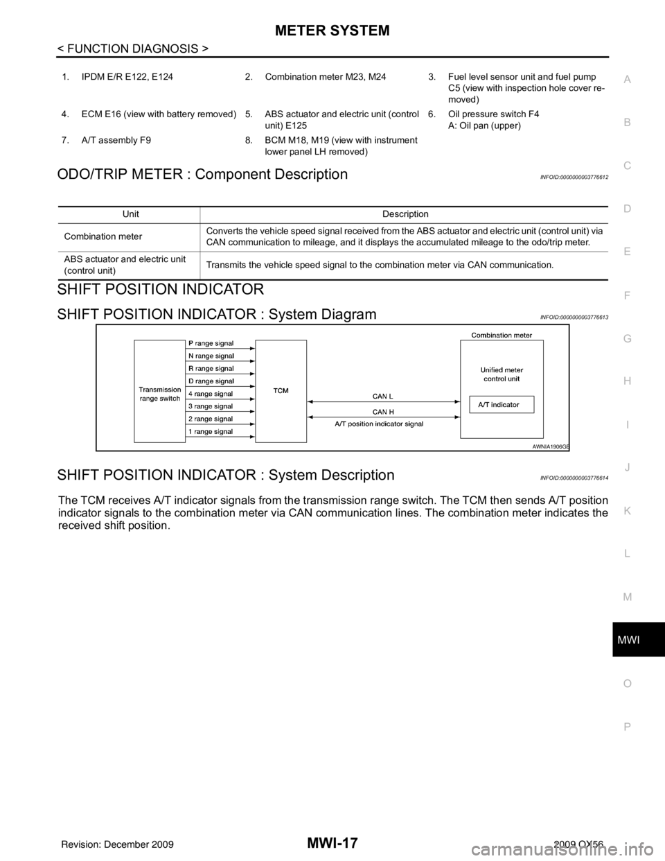
SHIFT POSITION INDICATOR : System DiagramINFOID:0000000003776613
SHIFT POSITION INDICATOR : System DescriptionINFOID:0000000003776614
The TCM receives A/T indicator signals from the tr ansmission range switch. The TCM then sends A/T position
indicator signals to the combination meter via CAN co mmunication lines. The combination meter indicates the
received shift position.
1. IPDM E/R E122, E124 2. Combination meter M23, M24 3. Fuel level sensor unit and fuel pump
C5 (view with inspection hole cover re-
moved)
4. ECM E16 (view with battery removed) 5. ABS actuator and electric unit (control unit) E1256. Oil pressure switch F4
A: Oil pan (upper)
7. A/T assembly F9 8. BCM M18, M19 (view with instrument
lower panel LH removed)
Unit Description
Combination meter Converts the vehicle speed signal
received from the ABS actuator and electric unit (control unit) via
CAN communication to mileage, and it displays the accumulated mileage to the odo/trip meter.
ABS actuator and electric unit
(control unit) Transmits the vehicle speed signal to the combination meter via CAN communication.
AWNIA1906GB
Revision: December 20092009 QX56
Page 2740 of 4171
MWI-18
< FUNCTION DIAGNOSIS >
METER SYSTEM
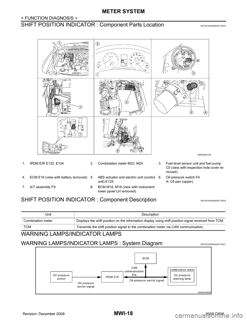
SHIFT POSITION INDICATOR : Component Parts Location
INFOID:0000000003776615
SHIFT POSITION INDICATOR : Component DescriptionINFOID:0000000003776616
WARNING LAMPS/INDICATOR LAMPS
WARNING LAMPS/INDICATOR LAMPS : System DiagramINFOID:0000000003776617
1. IPDM E/R E122, E124 2. Combination meter M23, M24 3. Fuel level sensor unit and fuel pump
C5 (view with inspection hole cover re-
moved)
4. ECM E16 (view with battery removed) 5. ABS actuator and electric unit (control
unit) E125 6. Oil pressure switch F4
A: Oil pan (upper)
7. A/T assembly F9 8. BCM M18, M19 (view with instrument
lower panel LH removed)
AWNIA0201ZZ
Unit Description
Combination meter Displays the shift position on the information display using shift position signal received from TCM.
TCM Transmits the shift position signal to the combination meter via CAN communication.
JSNIA0449GB
Revision: December 20092009 QX56
Page 2741 of 4171
MWI
METER SYSTEMMWI-19
< FUNCTION DIAGNOSIS >
C
DE
F
G H
I
J
K L
M B A
O P
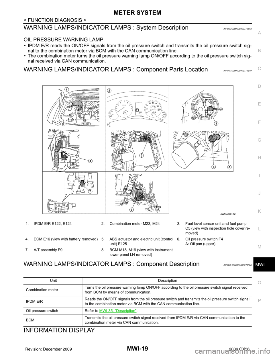
WARNING LAMPS/INDICATOR LAMPS : System DescriptionINFOID:0000000003776618
OIL PRESSURE WARNING LAMP
• IPDM E/R reads the ON/OFF signals from the oil pressure switch and transmits the oil pressure switch sig-
nal to the combination meter via BCM with the CAN communication line.
• The combination meter turns the oil pressure warning lamp ON/OFF according to the oil pressure switch sig- nal received via CAN communication.
WARNING LAMPS/INDICATOR LAMPS : Component Parts LocationINFOID:0000000003776619
WARNING LAMPS/INDICATOR LAMPS : Component DescriptionINFOID:0000000003776620
INFORMATION DISPLAY
1. IPDM E/R E122, E124 2. Combination meter M23, M24 3. Fuel level sensor unit and fuel pump
C5 (view with inspection hole cover re-
moved)
4. ECM E16 (view with battery removed) 5. ABS actuator and electric unit (control unit) E1256. Oil pressure switch F4
A: Oil pan (upper)
7. A/T assembly F9 8. BCM M18, M19 (view with instrument
lower panel LH removed)
AWNIA0201ZZ
Unit Description
Combination meter Turns the oil pressure warning lamp ON/OFF according to the oil pressure switch signal received
from BCM by means of communication.
IPDM E/R Reads the ON/OFF signals from the oil pressure switch and transmits the oil pressure switch signal
to the combination meter via BCM with the CAN communication line.
Oil pressure switch Refer to MWI-35, "
Description".
BCM Transmits the oil pressure switch signal received from IPDM E/R via CAN communication to the
combination meter via CAN communication.
Revision: December 20092009 QX56
Page 2743 of 4171
MWI
METER SYSTEMMWI-21
< FUNCTION DIAGNOSIS >
C
DE
F
G H
I
J
K L
M B A
O P
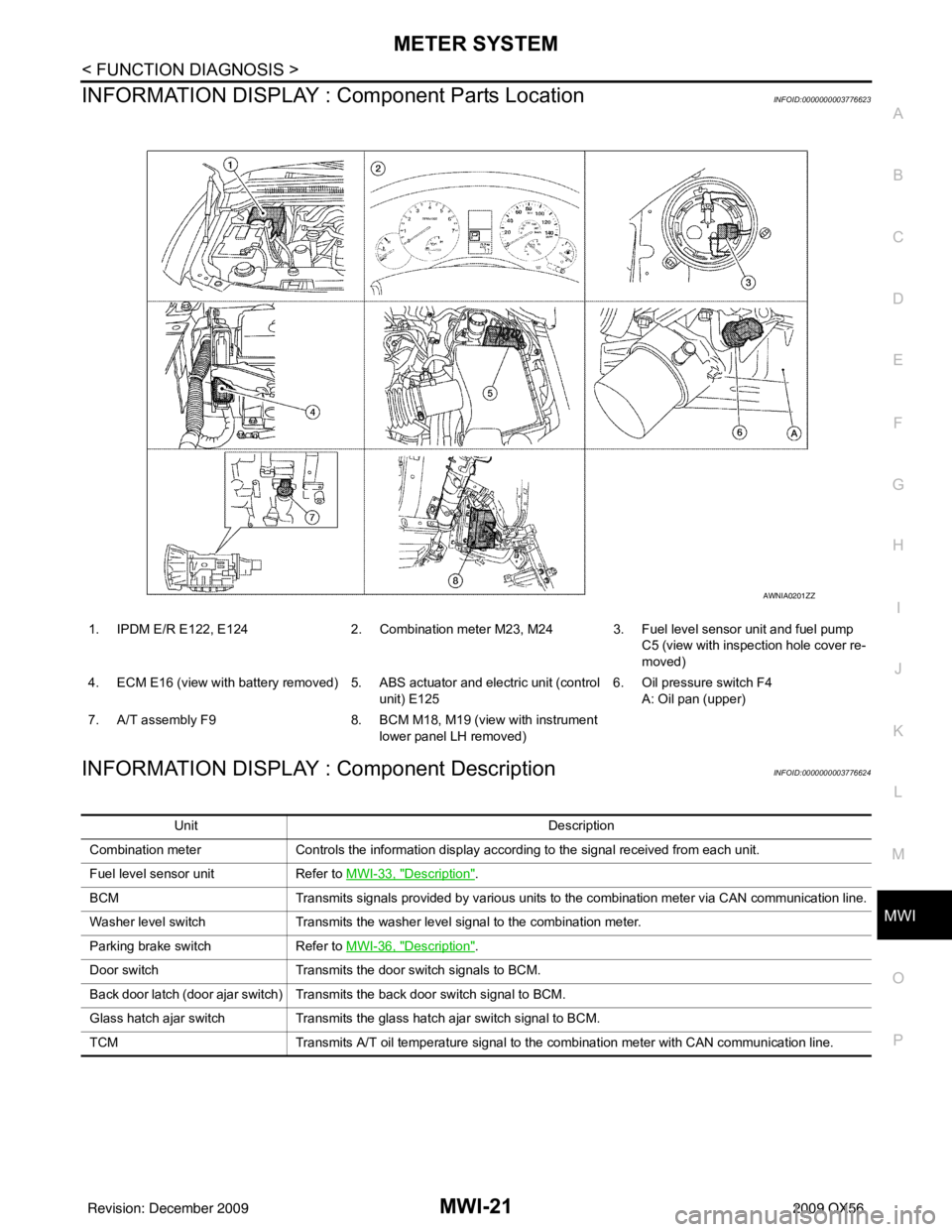
INFORMATION DISPLAY : Co mponent Parts LocationINFOID:0000000003776623
INFORMATION DISPLAY : Component DescriptionINFOID:0000000003776624
1. IPDM E/R E122, E124 2. Combination meter M23, M24 3. Fuel level sensor unit and fuel pump
C5 (view with inspection hole cover re-
moved)
4. ECM E16 (view with battery removed) 5. ABS actuator and electric unit (control unit) E1256. Oil pressure switch F4
A: Oil pan (upper)
7. A/T assembly F9 8. BCM M18, M19 (view with instrument
lower panel LH removed)
AWNIA0201ZZ
Unit Description
Combination meter Controls the information display according to the signal received from each unit.
Fuel level sensor unit Refer to MWI-33, "
Description".
BCM Transmits signals provided by various units to the combination meter via CAN communication line.
Washer level switch Transmits the washer level signal to the combination meter.
Parking brake switch Refer to MWI-36, "
Description".
Door switch Transmits the door switch signals to BCM.
Back door latch (door ajar switch) Transmits the back door switch signal to BCM.
Glass hatch ajar switch Transmits the glass hatch ajar switch signal to BCM.
TCM Transmits A/T oil temperature signal to the combination meter with CAN communication line.
Revision: December 20092009 QX56
Page 2755 of 4171
MWI
FUEL LEVEL SENSOR SIGNAL CIRCUITMWI-33
< COMPONENT DIAGNOSIS >
C
DE
F
G H
I
J
K L
M B A
O P
FUEL LEVEL SENSOR SIGNAL CIRCUIT
DescriptionINFOID:0000000003776636
The fuel level sensor unit and fuel pump detects the approx imate fuel level in the fuel tank and transmits the
fuel level signal to the combination meter.
Component Function CheckINFOID:0000000003776637
1.COMBINATION METER INPUT SIGNAL
1. Select “METER/M&A” on CONSULT-III.
2. Using “FUEL METER” of “DATA MONITOR”, comp are the value of DATA MONITOR with fuel gauge
pointer of combination meter.
Does the data monitor value approximately match the fuel gauge indication?
YES >> Inspection End.
NO >> Replace combination meter. Refer to MWI-102, "
Removal and Installation".
Diagnosis ProcedureINFOID:0000000003776638
1.CHECK HARNESS CONNECTOR
1. Turn ignition switch OFF.
2. Check combination meter and fuel level sensor unit terminals (meter-side and harness-side) for poor con- nection.
Is the inspection result normal?
YES >> GO TO 2
NO >> Repair or replace terminals or connectors.
2.CHECK FUEL LEVEL SENSOR UNIT CIRCUIT
1. Disconnect combination meter connector and fuel level sensor unit connector.
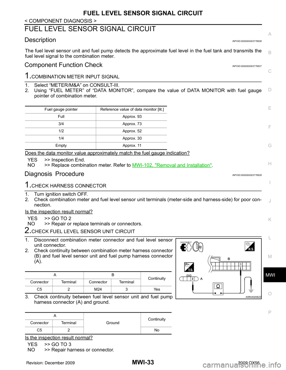
2. Check continuity between combination meter harness connector
(B) and fuel level sensor unit and fuel pump harness connector
(A).
3. Check continuity between fuel level sensor unit and fuel pump harness connector (A) and ground.
Is the inspection result normal?
YES >> GO TO 3
NO >> Repair harness or connector.
Fuel gauge pointer Reference value of data monitor [lit.]
Full Approx. 93
3/4 Approx. 73
1/2 Approx. 52
1/4 Approx. 30
Empty Approx. 11
AB
Continuity
Connector Terminal Connector Terminal
C5 2 M24 3 Yes
A GroundContinuity
Connector Terminal
C5 2 No
AWNIA0206ZZ
Revision: December 20092009 QX56
Page 2756 of 4171

MWI-34
< COMPONENT DIAGNOSIS >
FUEL LEVEL SENSOR SIGNAL CIRCUIT
3.CHECK FUEL LEVEL SENSOR UNIT GROUND CIRCUIT
1. Check continuity between combination meter harness connector (B) and fuel level sensor uni t and fuel pump harness connector
(A).
2. Check continuity between fuel level sensor unit and fuel pump harness connector (A) and ground.
Is the inspection result normal?
YES >> GO TO 4
NO >> Repair harness or connector.
4.CHECK INSTALLATION CONDITION
Check fuel level sensor unit installation, and check whether the float arm interferes or binds with any of the
internal components in the fuel tank.
Is the inspection result normal?
YES >> Inspection End.
NO >> Install the fuel level sensor unit properly.
Component InspectionINFOID:0000000003776639
1.REMOVE FUEL LEVEL SENSOR UNIT
Remove the fuel level sensor unit. Refer to FL-7, "
Removal and Installation".
>> GO TO 2
2.CHECK FUEL LEVEL SENSOR UNIT AND FUEL PUMP
Check the resistance between terminals 2 and 5.
*1 and *2: When float arm is in contact with stopper.
Is inspection result normal?
YES >> Inspection End.
NO >> Replace fuel level sensor unit and fuel pump. Refer to FL-7, "
Removal and Installation".
AB Continuity
Connector Terminal Connector Terminal
C5 5 M24 4 Yes
A GroundContinuity
Connector Terminal
C5 5 No
AWNIA0207ZZ
Te r m i n a l Float position
mm (in) Resistance value
(Approx.)
25 *1 Empty
7.5 (0.3)80Ω
*2 Full 218.9 (8.6)6Ω
LKIA0402E
Revision: December 20092009 QX56
Page 2804 of 4171

MWI-82
< ECU DIAGNOSIS >
IPDM E/R (INTELLIGENT POWER DISTRIBUTION MODULE ENGINE ROOM)
Te r m i n a lWire
color Signal name Signal
input/
output Measuring condition
Reference value(Approx.)
Igni-
tion
switch Operation or condition
1 B/Y Battery power supply Input OFF —Battery voltage
2 R Battery power supply Input OFF —Battery voltage
3 BR ECM relay Output —Ignition switch ON or START
Battery voltage
Ignition switch OFF or ACC 0V
4 W/L ECM relay Output —Ignition switch ON or START
Battery voltage
Ignition switch OFF or ACC 0V
6L Throttle control motor
relay Output —Ignition switch ON or START
Battery voltage
Ignition switch OFF or ACC 0V
7 W/B ECM relay control Input — Ignition switch ON or START
0V
Ignition switch OFF or ACC Battery voltage
8 R/B Fuse 54 Output —Ignition switch ON or START
Battery voltage
Ignition switch OFF or ACC 0V
10 G Fuse 45
(Canada only) Output ONDaytime light system active
0V
Daytime light system inactive Battery voltage
11 Y/B A/C compressor Output ON or
START A/C switch ON or defrost A/C
switch
Battery voltage
A/C switch OFF or defrost A/C
switch 0V
12 L/W Ignition switch sup-
plied power Input —OFF or ACC
0V
ON or START Battery voltage
13 B/Y Fuel pump relay Output — Ignition switch ON or START
Battery voltage
Ignition switch OFF or ACC 0V
14 Y/R Fuse 49 Output —Ignition switch ON or START
Battery voltage
Ignition switch OFF or ACC 0V
15 LG/B Fuse 50 Output —Ignition switch ON or START
Battery voltage
Ignition switch OFF or ACC 0V
16 G Fuse 51 Output —Ignition switch ON or START
Battery voltage
Ignition switch OFF or ACC 0V
17 W Fuse 55 Output —Ignition switch ON or START
Battery voltage
Ignition switch OFF or ACC 0V
19 W/R Starter motor Output START—Battery voltage
21 BR Ignition switch sup-
plied power
Input —OFF or ACC
0V
START Battery voltage
22 G Battery power supply Output OFF —Battery voltage
23 GR/W Door mirror defogger
output signal Output —When rear defogger switch is
ON
Battery voltage
When raker defogger switch is
OFF 0V
24 L Cooling fan relay Output — Conditions correct for cooling
fan operation
Battery voltage
Conditions not correct for
cooling fan operation 0V
Revision: December 20092009 QX56