Page 2162 of 4171

FUEL LEVEL SENSOR UNIT, FUEL FILTER AND FUEL PUMP ASSEMBLYFL-9
< REMOVAL AND INSTALLATION >
C
DE
F
G H
I
J
K L
M A
FL
NP
O
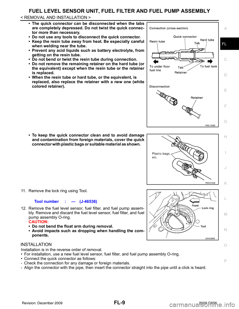
• The quick connector can be
disconnected when the tabs
are completely depressed. Do not twist the quick connec-
tor more than necessary.
• Do not use any tools to di sconnect the quick connector.
• Keep the resin tube away from heat. Be especially careful
when welding near the tube.
• Prevent any acid liquids such as battery electrolyte, from getting on the resin tube.
• Do not bend or twist the resin tube during connection.
• Do not remove the remaining retainer on the hard tube (or
the equivalent) except when the resin tube or the retainer
is replaced.
• When the resin tube or hard tube, or the equivalent, is
replaced, also replace the retainer with a new one (white
colored retainer).
• To keep the quick connector clean and to avoid damage
and contamination from foreign materials, cover the quick
connector with plastic bags or suitable material as shown.
11. Remove the lock ring using Tool.
12. Remove the fuel level sensor, fuel filter, and fuel pump assem- bly. Remove and discard the fuel level sensor, fuel filter, and fuel
pump assembly O-ring.
CAUTION:
• Do not bend the float arm during removal.
• Avoid impacts such as droppi ng when handling the com-
ponents.
INSTALLATION
Installation is in the reverse order of removal.
• For installation, use a new fuel level sensor, fuel filter, and fuel pump assembly O-ring.
• Connect the quick connector as follows:
- Check the connection for any damage or foreign materials.
- Align the connector with the pipe, t hen insert the connector straight into the pipe until a click is heard.
PBIC1268E
PBIC0163E
Tool number : — (J-46536)
LBIA0389E
Revision: December 20092009 QX56
Page 2163 of 4171
FL-10
< REMOVAL AND INSTALLATION >
FUEL LEVEL SENSOR UNIT, FUEL FILTER AND FUEL PUMP ASSEMBLY
- After connecting the quick connector, make sure that the connec-
tion is secure by checking as follows:
- Pull the tube and the connector to make sure they are securely
connected.
- Visually inspect the connector to make sure the two retainer tabs are securely connected.
INSPECTION AFTER INSTALLATION
1. Turn the ignition switch ON but do not start engi ne, then check the fuel pipes and hose connections for
leaks while applying fuel pressure to the system.
2. Start the engine and rev it above idle speed, then check t hat there are no fuel leaks at any of the fuel pipe
and hose connections.
PBIC1653E
Revision: December 20092009 QX56
Page 2164 of 4171
FUEL TANKFL-11
< REMOVAL AND INSTALLATION >
C
DE
F
G H
I
J
K L
M A
FL
NP
O
FUEL TANK
Removal and InstallationINFOID:0000000003771774
1. Inspection hole cover
2. Inspection hole cover O-ring 3. Lock ring
4. Fuel level sensor, fuel filter, and fuel pump assembly 5. Fuel tank
6. Fuel tank protector
7. Fuel tank protector clips 8. Fuel tank straps 9. Fuel level sensor, fuel filter, and fuel
pump assembly O-ring
10. Fuel filler hose 11. Fuel filler pipe 12. Fuel filler cup
AWBIA0522GB
Revision: December 20092009 QX56
Page 2166 of 4171
FUEL TANKFL-13
< REMOVAL AND INSTALLATION >
C
DE
F
G H
I
J
K L
M A
FL
NP
O
13. Remove the inspection hole cover by turning the retainers 90
°
degrees clockwise.
• Remove the O-ring.
14. Disconnect the fuel level sensor, fuel filter, and fuel pump assembly electrical connector, the EVAP hose, and the fuel feed
hose.
Disconnect the quick connector as follows:
• Hold the sides of the connector, push in tabs and pull out the
tube.
• If the connector and the tube are stuck together, push and pull several times until they start to move. Then disconnect them
by pulling.
CAUTION:
LBIA0382E
LBIA0383E
SFE562A
Revision: December 20092009 QX56
Page 2168 of 4171

FUEL TANKFL-15
< REMOVAL AND INSTALLATION >
C
DE
F
G H
I
J
K L
M A
FL
NP
O
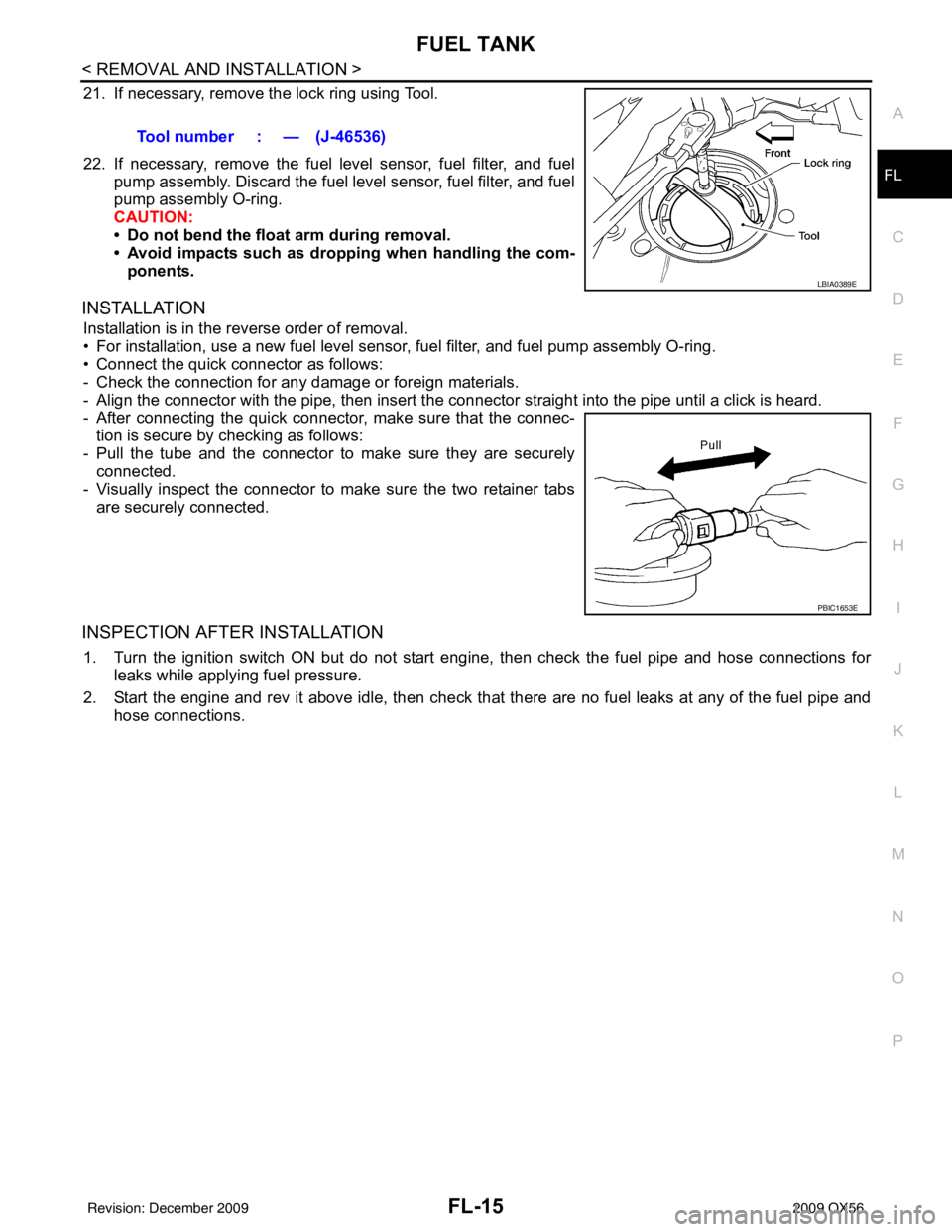
21. If necessary, remove the lock ring using Tool.
22. If necessary, remove the fuel level sensor, fuel filter, and fuel
pump assembly. Discard the fuel level sensor, fuel filter, and fuel
pump assembly O-ring.
CAUTION:
• Do not bend the float arm during removal.
• Avoid impacts such as droppi ng when handling the com-
ponents.
INSTALLATION
Installation is in the reverse order of removal.
• For installation, use a new fuel level sensor, fuel filter, and fuel pump assembly O-ring.
• Connect the quick connector as follows:
- Check the connection for any damage or foreign materials.
- Align the connector with the pipe, t hen insert the connector straight into the pipe until a click is heard.
- After connecting the quick connector, make sure that the connec-
tion is secure by checking as follows:
- Pull the tube and the connector to make sure they are securely connected.
- Visually inspect the connector to make sure the two retainer tabs are securely connected.
INSPECTION AFTER INSTALLATION
1. Turn the ignition switch ON but do not start en gine, then check the fuel pipe and hose connections for
leaks while applying fuel pressure.
2. Start the engine and rev it above idle, then check that there are no fuel leaks at any of the fuel pipe and
hose connections. Tool number : — (J-46536)
LBIA0389E
PBIC1653E
Revision: December 20092009 QX56
Page 2169 of 4171
FL-16
< DISASSEMBLY AND ASSEMBLY >
FUEL LEVEL SENSOR UNIT, FUEL FILTER AND FUEL PUMP ASSEMBLY
DISASSEMBLY AND ASSEMBLY
FUEL LEVEL SENSOR UNIT, FUEL FILTER AND FUEL PUMP ASSEMBLY
Disassembly and AssemblyINFOID:0000000003771775
Fuel Level Sender Unit
Disassembly
1. Disconnect the harness connectors and the wire connector.
2. Remove the fuel sensor from the pump assembly.
3. Depress the tabs and remove the floater arm assembly.
Assembly
Assembly is in the reverse order of disassembly.
AWBIA0680ZZ
1. Harness connector 2. Sending unit module 3. Fuel sensor
4. Floater arm assembly
Revision: December 20092009 QX56
Page 2212 of 4171

GI-18
< HOW TO USE THIS MANUAL >
TERMINOLOGY
Nonvolatile random access memory NVRAM***
On board diagnostic system OBD system Self-diagnosis
Open loop OL Open loop
Oxidation catalyst OC Catalyst
Oxidation catalytic converter system OC system ***
Oxygen sensor O2S Exhaust gas sensor
Park neutral position switch PNP switch Park / neutral switch/ Inhibitor switch / Neu-
tral position switch.
Park position switch *** Park switch
Periodic trap oxidizer system PTOX system ***
Positive crankcase ventilation PCV Positive crankcase ventilation
Positive crankcase ventilation valve PCV valve PCV valve
Powertrain cont rol module PCM ***
Programmable read only memory PROM ***
Pulsed secondary air injection control sole-
noid valve PAIRC solenoid valve
AIV control solenoid valve
Pulsed secondary air injection system PAIR system Air induction valve (AIV) control
Pulsed secondary air injection valve PAIR valve Air induction valve
Random access memory RAM ***
Read only memory ROM ***
Scan tool ST ***
Secondary air injection pump AIR pump***
Secondary air injection system AIR system ***
Sequential multiport fuel injection system SFI system Sequential fuel injection
Service reminder indicator SRI***
Simultaneous multiport fuel injection sys-
tem ***
Simultaneous fuel injection
Smoke puff limiter system SPL system ***
Supercharger SC ***
Supercharger bypass SCB ***
System readiness test SRT ***
Thermal vacuum valve TVVThermal vacuum valve
Three way catalyst TWCCatalyst
Three way catalytic converter system TWC system ***
Three way + oxidation catalyst TWC + OCCatalyst
Three way + oxidation catalytic converter
system TWC + OC system
***
Throttle body TB Throttle chamber
SPI body
Throttle body fuel injection system TBI system Fuel injection control
Throttle position TP Throttle position
Throttle position sensor TPS Throttle sensor
Throttle position switch TP switch Throttle switch
Torque converter clutch solenoid valve TCC solenoid valve Lock-up cancel solenoid
Lock-up solenoid
Transmission range switch *** Park/neutral position switch
NEW TERM
NEW ACRONYM /
ABBREVIATION OLD TERM
Revision: December 20092009 QX56
Page 2220 of 4171

GI-26
< PRECAUTION >
PRECAUTIONS
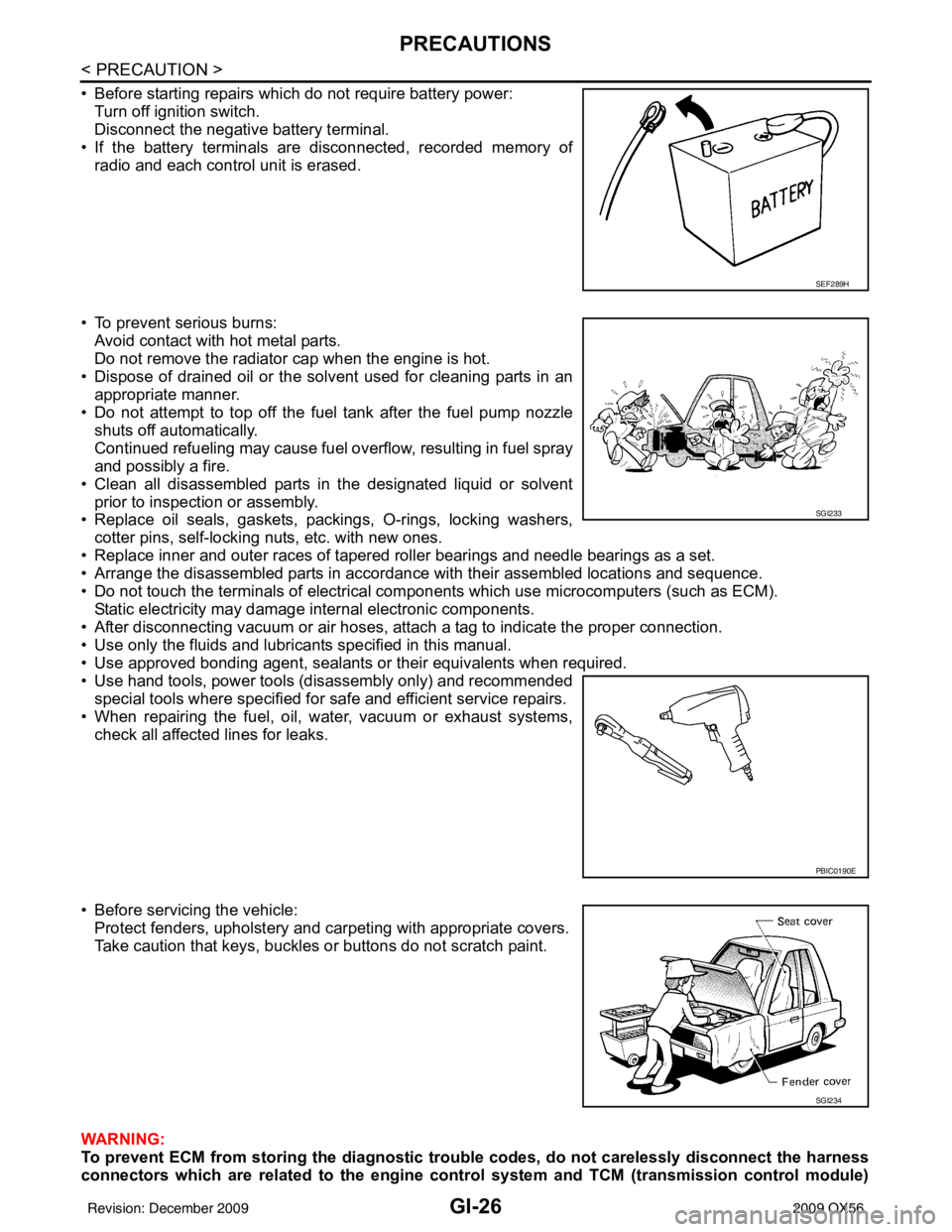
• Before starting repairs which do not require battery power:Turn off ignition switch.
Disconnect the negative battery terminal.
• If the battery terminals are disconnected, recorded memory of radio and each control unit is erased.
• To prevent serious burns: Avoid contact with hot metal parts.
Do not remove the radiator cap when the engine is hot.
• Dispose of drained oil or the solvent used for cleaning parts in an appropriate manner.
• Do not attempt to top off the fuel tank after the fuel pump nozzle
shuts off automatically.
Continued refueling may cause fuel overflow, resulting in fuel spray
and possibly a fire.
• Clean all disassembled parts in the designated liquid or solvent prior to inspection or assembly.
• Replace oil seals, gaskets, packings, O-rings, locking washers,
cotter pins, self-locking nuts, etc. with new ones.
• Replace inner and outer races of tapered roller bearings and needle bearings as a set.
• Arrange the disassembled parts in accordance with their assembled locations and sequence.
• Do not touch the terminals of electrical com ponents which use microcomputers (such as ECM).
Static electricity may damage internal electronic components.
• After disconnecting vacuum or air hoses, atta ch a tag to indicate the proper connection.
• Use only the fluids and lubricants specified in this manual.
• Use approved bonding agent, sealants or their equivalents when required.
• Use hand tools, power tools (disassembly only) and recommended special tools where specified for safe and efficient service repairs.
• When repairing the fuel, oil, water, vacuum or exhaust systems, check all affected lines for leaks.
• Before servicing the vehicle: Protect fenders, upholstery and carpeting with appropriate covers.
Take caution that keys, buckles or buttons do not scratch paint.
WARNING:
To prevent ECM from storing the diagnostic tro uble codes, do not carelessly disconnect the harness
connectors which are related to the engine control system and TCM (transmission control module)
SEF289H
SGI233
PBIC0190E
SGI234
Revision: December 20092009 QX56