2009 INFINITI QX56 transmission
[x] Cancel search: transmissionPage 2684 of 4171
PERIODIC MAINTENANCEMA-11
< ON-VEHICLE MAINTENANCE >
C
DE
F
G H
I
J
K L
M B
MA
N
O A
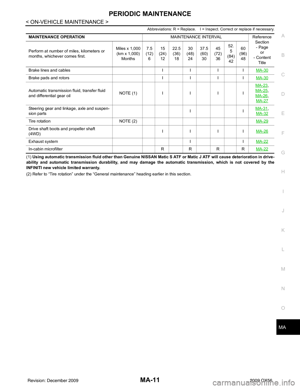
Abbreviations: R = Replace. I = Inspec
t. Correct or replace if necessary.
(1) Using automatic transmission fluid other th an Genuine NISSAN Matic S ATF or Matic J ATF will cause deterioration in drive-
ability and automatic transmission durability, and may damage the automatic transmission, which is not covered by the
INFINITI new vehicle limited warranty.
(2) Refer to “Tire rotation” under the “General maintenance” heading earlier in this section.
MAINTENANCE OPERATION
MAINTENANCE INTERVALReference
Section
- Page or
- Content
Title
Perform at number of miles, kilometers or
months, whichever comes first.
Miles x 1,000
(km x 1,000)
Months 7.5
(12)
6 15
(24)
12 22.5
(36)
18 30
(48)
24 37.5
(60)
30 45
(72)
36 52.
5
(84) 42 60
(96)
48
Brake lines and cables IIIIMA-30
Brake pads and rotors IIIIMA-30
Automatic transmission fluid, transfer fluid
and differential gear oil N
O TE (1)IIII MA-23
,
MA-25
,
MA-26
,
MA-27
Steering gear and linkage, axle and suspen-
sion parts II
MA-31,
MA-32
Tire rotation NOTE (2) MA-29
Drive shaft boots and propeller shaft
(4WD)IIII
MA-26
Exhaust system IIMA-22
In-cabin microfilter RRRRMA-22
Revision: December 20092009 QX56
Page 2685 of 4171
MA-12
< ON-VEHICLE MAINTENANCE >
RECOMMENDED FLUIDS AND LUBRICANTS
RECOMMENDED FLUIDS AND LUBRICANTS
Fluids and LubricantsINFOID:0000000003776984
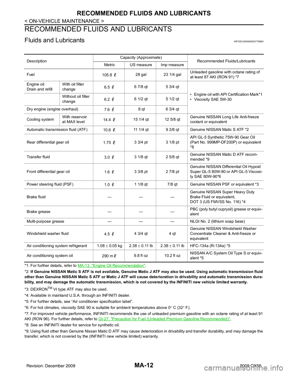
*1: For further details, refer to MA-13, "Engine Oil Recommendation".
*2: If Genuine NISSAN Matic S ATF is not available, Genuine Matic J ATF may also be used. Using automatic transmission fluid
other than Genuine NISSAN Matic S ATF or Matic J ATF will cause deterioration in drivability and automatic transmission dura-
bility, and may damage the automatic transmission, which is not covered by the INFINITI new vehicle limited warranty.
*3: DEXRON
TM VI type ATF may also be used.
*4: Available in mainland U.S.A. through an INFINITI dealer.
*5: For further details, see “Air conditioner specification label”.
*6: For hot climates, viscosity SAE 90 is suitable for ambient te mperatures above 0° C (32 ° F).
*7: For improved vehicle performance, INFINITI recommends the use of unleaded premium gasoline with an octane rating of at leas t 91
AKI (RON 96). For further details, refer to GI-27, "
Precaution for Fuel (Unleaded Premium Gasoline Recommended)",
*8: See an INFINITI dealer for service for synthetic oil.
*9: Using fluid other than Genuine Nissan Matic D ATF may cause deterioration in drivability and transfer durability, and may d amage the
transfer, which is not covered by the (INFINITI new vehicle limited) warranty. Description
Capacity (Approximate)
Recommended Fluids/Lubricants
Metric US measure Imp measure
Fuel 105.8 28 gal 23 1/4 gal Unleaded gasoline with octane rating of
at least 87 AKI (RON 91) *7
Engine oil
Drain and refill With oil filter
change
6.5
6 7/8 qt 5 3/4 qt
• Engine oil with API Certification Mark*1
• Viscosity SAE 5W-30
Without oil filter
change
6.2
6 1/2 qt 5 1/2 qt
Dry engine (engine overhaul) 7.6 8 qt
6 3/4 qt
Cooling system With reservoir
at MAX level
14.4
15 1/4 qt 12 5/8 qt Genuine NISSAN Long Life Anti-freeze
coolant or equivalent
Automatic transmission fluid (ATF) 10.6 11 1/4 qt 9 3/8 qt Genuine NISSAN Matic S ATF *2
Rear differential gear oil 1.75 3 3/4 pt 3 1/8 pt API GL-5 Synthetic 75W-90 Gear Oil
(Part No. 999MP-DF200P) or equivalent
*8
Transfer fluid 3.0 3 1/8 qt 2 5/8 qt Genuine NISSAN Matic D ATF recom-
mended *9
Front differential gear oil 1.6 3 3/8 pt 2 7/8 pt Genuine NISSAN Differential Oil Hypoid
Super GL-5 80W-90 or API GL-5 Viscosi-
ty SAE 80W-90*6
Power steering fluid (PSF) 1.0 1 1/8 qt 7/8 qt Genuine NISSAN PSF or equivalent *3
Brake fluid —— —Genuine NISSAN Super Heavy Duty
Brake Fluid or equivalent,
DOT 3 (US FMVSS No. 116) *4
Brake grease —— —PBC (poly butyl cuprysil) grease or equiv-
alent
Multi-purpose grease —— — NLGI No. 2 (lithium soap base)
Windshield washer fluid 4.5 4 3/4 qt
4 qtGenuine NISSAN Windshield Washer
Concentrate Cleaner & Anti-freeze or
equivalent
Air conditioning system refrigerant 1.08 ± 0.05 kg 2.38 ± 0.11 lb 2.38 ± 0.11 lb HFC-134a (R-134a) *5
Air conditioning system oil 290 m9.8 fl oz 10.2 fl oz NISSAN A/C System Oil Type S or equiv-
alent *5
Revision: December 20092009 QX56
Page 2696 of 4171

CHASSIS AND BODY MAINTENANCEMA-23
< ON-VEHICLE MAINTENANCE >
C
DE
F
G H
I
J
K L
M B
MA
N
O A
Checking the A/T Fluid (ATF)INFOID:0000000004215539
CAUTION:
If using the vehicle for towing, the A/T fluid must be replaced as specified. Refer to
MA-8, "
Introduc-
tion of Periodic Maintenance".
1. Before driving, the A/T fluid level can be checked at A/T fluid temperatures of 30 ° to 50 ° C (86 ° to 122° F) using the “COLD”
range on the A/T fluid level gauge as follows:
a. Park the vehicle on a level surface and set the parking brake.
b. Start the engine and move the A/T shift selector through each gear position. Shift the A/T shift selector into the “P” position.
c. Check the A/T fluid level with the engine idling.
d. Remove the A/T fluid level gauge and wipe it clean with a lint- free paper.
CAUTION:
When wiping the A/T fluid from the A/T fluid level gauge,
always use a lint-free paper, not a cloth.
e. Re-insert the A/T fluid level gauge into the A/T fluid charging pipe until the cap contacts the top of the A/T fluid charging pipe
as shown.
CAUTION:
To check A/T fluid level, insert th e A/T fluid level gauge until
the cap contacts the top of the A/T fluid charging pipe, with
the gauge reversed from the normal inserted position.
f. Remove the A/T fluid level gauge and note the A/T fluid level. If the A/T fluid level is at low side of range, add A/T fluid to the
transmission through the A/T fluid charging pipe.
CAUTION:
Do not overfill the tran smission with A/T fluid.
g. Install the A/T fluid level gauge and the A/T fluid level gauge bolt.
2. Warm up the engine and transmission.
3. Check for any A/T fluid leaks.
4. Drive the vehicle to increase the A/T fluid temperature to 80 ° C (176 ° F).
5. Allow the A/T fluid temperature to fall to approximately 65 °C (149° F). Use the CONSULT-III to monitor the
A/T fluid temperature as follows:
LLIA0071E
A/T fluid level
gauge bolt : Refer to
TM-214, "Removal and Installation (2WD)" or TM-216, "Removal
and Installation (4WD)"
SCIA2899E
SLIA0016E
Revision: December 20092009 QX56
Page 2697 of 4171
MA-24
< ON-VEHICLE MAINTENANCE >
CHASSIS AND BODY MAINTENANCE
NOTE:
The A/T fluid level will be significantly affected by the A/T fluid temperature as shown. Therefore monitor
the A/T fluid temperature data using the CONSULT-III.
a. Connect CONSULT-III to data link connector.
b. Select “MAIN SIGNALS” in “DATA MONI TOR” mode for “A/T” with CONSULT-III.
c. Read out the value of “ATF TEMP 1”.
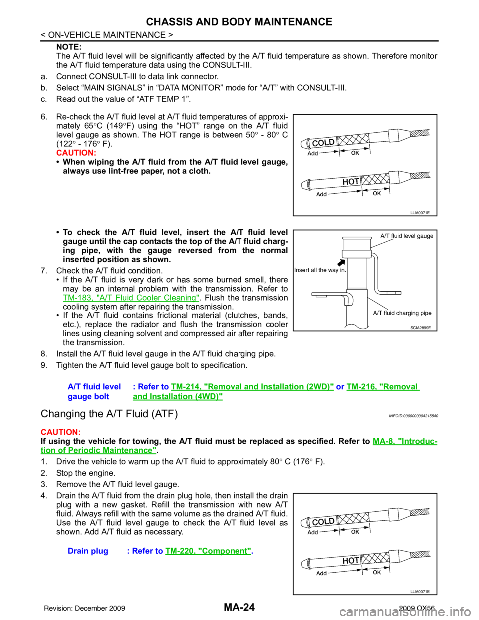
6. Re-check the A/T fluid level at A/T fluid temperatures of approxi- mately 65 °C (149° F) using the “HOT” range on the A/T fluid
level gauge as shown. The HOT range is between 50 ° - 80 ° C
(122° - 176 ° F).
CAUTION:
• When wiping the A/T fluid from the A/T fluid level gauge,
always use lint-free paper, not a cloth.
• To check the A/T fluid level , insert the A/T fluid level
gauge until the cap contacts the top of the A/T fluid charg-
ing pipe, with the gauge reversed from the normal
inserted position as shown.
7. Check the A/T fluid condition. • If the A/T fluid is very dark or has some burned smell, theremay be an internal problem with the transmission. Refer to
TM-183, "
A/T Fluid Cooler Cleaning". Flush the transmission
cooling system after repairing the transmission.
• If the A/T fluid contains frictional material (clutches, bands, etc.), replace the radiator and flush the transmission cooler
lines using cleaning solvent and compressed air after repairing
the transmission.
8. Install the A/T fluid level gauge in the A/T fluid charging pipe.
9. Tighten the A/T fluid level gauge bolt to specification.
Changing the A/T Fluid (ATF)INFOID:0000000004215540
CAUTION:
If using the vehicle for towing, the A/T fl uid must be replaced as specified. Refer to MA-8, "
Introduc-
tion of Periodic Maintenance".
1. Drive the vehicle to warm up the A/T fluid to approximately 80 ° C (176 ° F).
2. Stop the engine.
3. Remove the A/T fluid level gauge.
4. Drain the A/T fluid from the drain plug hole, then install the drain plug with a new gasket. Refill the transmission with new A/T
fluid. Always refill with the same volume as the drained A/T fluid.
Use the A/T fluid level gauge to check the A/T fluid level as
shown. Add A/T fluid as necessary.
LLIA0071E
A/T fluid level
gauge bolt : Refer to
TM-214, "Removal and Installation (2WD)" or TM-216, "Removal
and Installation (4WD)"
SCIA2899E
Drain plug : Refer to TM-220, "Component".
LLIA0071E
Revision: December 20092009 QX56
Page 2698 of 4171
CHASSIS AND BODY MAINTENANCEMA-25
< ON-VEHICLE MAINTENANCE >
C
DE
F
G H
I
J
K L
M B
MA
N
O A
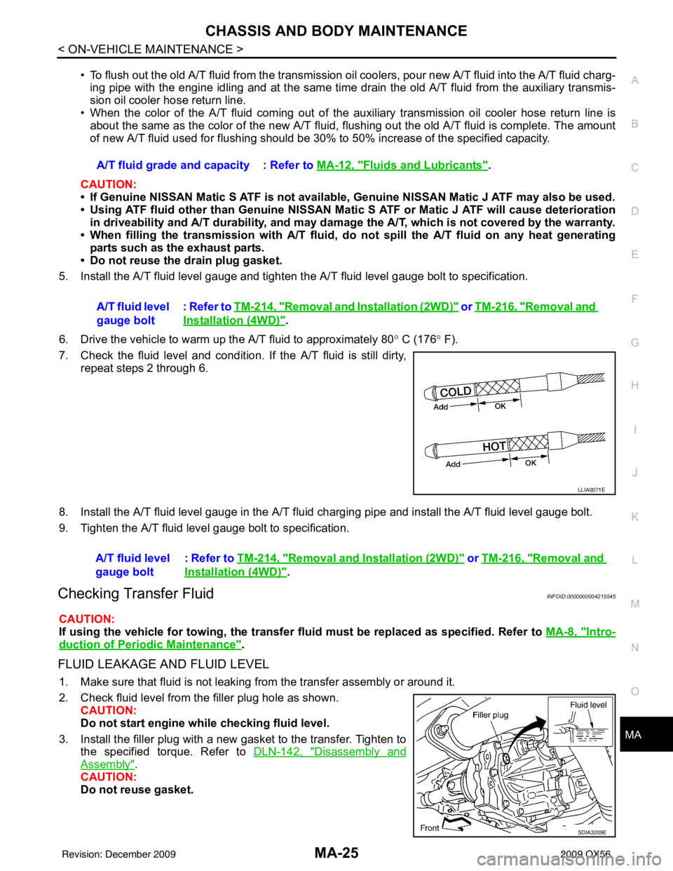
• To flush out the old A/T fluid from the transmission o
il coolers, pour new A/T fluid into the A/T fluid charg-
ing pipe with the engine idling and at the same time drain the old A/T fluid from the auxiliary transmis-
sion oil cooler hose return line.
• When the color of the A/T fluid coming out of the aux iliary transmission oil cooler hose return line is
about the same as the color of the new A/T fluid, flushing out the old A/T fluid is complete. The amount
of new A/T fluid used for flushing should be 30% to 50% increase of the specified capacity.
CAUTION:
• If Genuine NISSAN Matic S ATF is not available, Genuine NISSAN Matic J ATF may also be used.
• Using ATF fluid other than Genuine NISSAN Matic S ATF or Matic J ATF will cause deterioration
in driveability and A/T durability, and may damage the A/T, which is not covered by the warranty.
• When filling the transmission with A/T fluid, do not spill the A/T fluid on any heat generating
parts such as the exhaust parts.
• Do not reuse the drain plug gasket.
5. Install the A/T fluid level gauge and tighten t he A/T fluid level gauge bolt to specification.
6. Drive the vehicle to warm up the A/T fluid to approximately 80 ° C (176 ° F).
7. Check the fluid level and condition. If the A/T fluid is still dirty, repeat steps 2 through 6.
8. Install the A/T fluid level gauge in the A/T fluid charging pipe and install the A/T fluid level gauge bolt.
9. Tighten the A/T fluid level gauge bolt to specification.
Checking Transfer FluidINFOID:0000000004215545
CAUTION:
If using the vehicle for towing, the transfer fluid must be replaced as specified. Refer to MA-8, "
Intro-
duction of Periodic Maintenance".
FLUID LEAKAGE AND FLUID LEVEL
1. Make sure that fluid is not leaking from the transfer assembly or around it.
2. Check fluid level from the filler plug hole as shown.
CAUTION:
Do not start engine while checking fluid level.
3. Install the filler plug with a new gasket to the transfer. Tighten to the specified torque. Refer to DLN-142, "
Disassembly and
Assembly".
CAUTION:
Do not reuse gasket. A/T fluid grade and capacity : Refer to MA-12, "
Fluids and Lubricants".
A/T fluid level
gauge bolt : Refer to
TM-214, "
Removal and Installation (2WD)" or TM-216, "Removal and
Installation (4WD)".
LLIA0071E
A/T fluid level
gauge bolt : Refer to TM-214, "Removal and Installation (2WD)" or TM-216, "Removal and
Installation (4WD)".
SDIA3209E
Revision: December 20092009 QX56
Page 2847 of 4171
![INFINITI QX56 2009 Factory Service Manual PCS-10
< FUNCTION DIAGNOSIS >[IPDM E/R]
POWER CONSUMPTION CONTROL SYSTEM
POWER CONSUMPTIO
N CONTROL SYSTEM
System DiagramINFOID:0000000003776493
System DescriptionINFOID:0000000003776494
OUTLINE
• I INFINITI QX56 2009 Factory Service Manual PCS-10
< FUNCTION DIAGNOSIS >[IPDM E/R]
POWER CONSUMPTION CONTROL SYSTEM
POWER CONSUMPTIO
N CONTROL SYSTEM
System DiagramINFOID:0000000003776493
System DescriptionINFOID:0000000003776494
OUTLINE
• I](/manual-img/42/57031/w960_57031-2846.png)
PCS-10
< FUNCTION DIAGNOSIS >[IPDM E/R]
POWER CONSUMPTION CONTROL SYSTEM
POWER CONSUMPTIO
N CONTROL SYSTEM
System DiagramINFOID:0000000003776493
System DescriptionINFOID:0000000003776494
OUTLINE
• IPDM E/R incorporates a power consumption control function that reduces the power consumption accord-
ing to the vehicle status.
• IPDM E/R changes its status (control mode) with the sleep wake up signal received from BCM via CAN com-
munication.
Normal mode (wake-up)- CAN communication is normally performed with other control units.
- Individual unit control by IPDM E/R is normally performed.
Low power consumption mode (sleep)- Low power consumption control is active.
- CAN transmission is stopped.
SLEEP MODE ACTIVATION
• IPDM E/R judges that the sleep-ready conditions are fulfilled when the ignition switch is OFF and none of theconditions below are present. Then it transmits a sleep-ready signal (ready) to BCM via CAN communica-
tion.
- Front wiper fail-safe operation
- Outputting signals to actuators
- Switches or relays operating
- Auto active test is starting
- Emergency OFF
- Output requests are being received from control units via CAN communication.
• IPDM E/R stops CAN communication and enters the low power consumption mode when it receives a sleep
wake up signal (sleep) from BCM and the sleep-ready conditions are fulfilled.
WAKE-UP OPERATION
• IPDM E/R changes from the low power consumption mode to the normal mode when it receives a sleep
wake-up signal (wake up) from BCM or any of the following conditions is fulfilled. In addition, it transmits a
sleep-ready signal (not-ready) to BCM via CAN communication to report the CAN communication start.
- Ignition switch ON
- An output request is received from a control unit via CAN communication.
AWMIA0082GB
Revision: December 20092009 QX56
Page 3076 of 4171
RAX-1
TRANSMISSION & DRIVELINE
CEF
G H
I
J
K L
M
SECTION RAX
A
B
RAX
N
O P
CONTENTS
REAR AXLE
PRECAUTION ................ ...............................2
PRECAUTIONS .............................................. .....2
Precaution for Supplemental Restraint System
(SRS) "AIR BAG" and "SEAT BELT PRE-TEN-
SIONER" ............................................................. ......
2
Precaution Necessary for Steering Wheel Rota-
tion After Battery Disconnect .....................................
2
Caution ......................................................................3
PREPARATION ............................................4
PREPARATION .............................................. .....4
Special Service Tool ........................................... ......4
Commercial Service Tool ..........................................4
SYMPTOM DIAGNOSIS ...............................5
NOISE, VIBRATION AND HARSHNESS
(NVH) TROUBLESHOOTING ........................ .....
5
NVH Troubleshooting Chart ................................ ......5
ON-VEHICLE MAINTENANCE .....................6
WHEEL HUB .... .............................................. .....6
On-Vehicle Inspection and Service ..................... .....6
REMOVAL AND INSTALLATION ................7
WHEEL HUB ......................................................7
Removal and Installation ..................................... .....7
REAR DRIVE SHAFT .........................................9
Component ...............................................................9
Removal and Installation ..........................................9
DISASSEMBLY AND ASSEMBLY ..............11
REAR DRIVE SHAFT ........................................11
Disassembly and Assembly ................................. ....11
SERVICE DATA AND SPECIFICATIONS
(SDS) ............... .............................................
16
SERVICE DATA AND SPECIFICATIONS
(SDS) .................................................................
16
Wheel Bearing ..................................................... ....16
Drive Shaft ...............................................................16
Boot Bands ..............................................................16
Revision: December 20092009 QX56
Page 3332 of 4171
![INFINITI QX56 2009 Factory Service Manual SEC-22
< COMPONENT DIAGNOSIS >[WITH INTELLIGENT KEY SYSTEM]
U1000 CAN COMM CIRCUIT
COMPONENT DIAGNOSIS
U1000 CAN COMM CIRCUIT
DescriptionINFOID:0000000003775884
CAN (Controller Area Network) is a seri INFINITI QX56 2009 Factory Service Manual SEC-22
< COMPONENT DIAGNOSIS >[WITH INTELLIGENT KEY SYSTEM]
U1000 CAN COMM CIRCUIT
COMPONENT DIAGNOSIS
U1000 CAN COMM CIRCUIT
DescriptionINFOID:0000000003775884
CAN (Controller Area Network) is a seri](/manual-img/42/57031/w960_57031-3331.png)
SEC-22
< COMPONENT DIAGNOSIS >[WITH INTELLIGENT KEY SYSTEM]
U1000 CAN COMM CIRCUIT
COMPONENT DIAGNOSIS
U1000 CAN COMM CIRCUIT
DescriptionINFOID:0000000003775884
CAN (Controller Area Network) is a serial communication
line for real time applications. It is an on-vehicle mul-
tiplex communication line with high data communication speed and excellent error detection ability. Modern
vehicle is equipped with many electronic control unit, and each control unit shares information and links with
other control units during operation (not independent). In CAN communication, control units are connected
with 2 communication lines (CAN-H line, CAN-L line) al lowing a high rate of information transmission with less
wiring. Each control unit transmits/receives data but selectively reads required data only.
CAN Communication Signal Chart, refer to LAN-44, "
CAN Communication Signal Chart".
DTC LogicINFOID:0000000003775885
DTC DETECTION LOGIC
Diagnosis ProcedureINFOID:0000000003775886
1.PERFORM SELF DIAGNOSTIC
1. Turn ignition switch ON and wait for 2 seconds or more.
2. Check “Self Diagnostic Result”.
Is
“CAN COMM CIRCUIT” displayed?
YES >> Refer to LAN-5, "CAN Communication Control Circuit".
NO >> Refer to GI-38, "
Intermittent Incident".
DTCCONSULT-III display
description DTC Detection Condition
Possible cause
U1000 CAN COMM CIRCUIT When Intelligent Key unit cannot communi-
cate CAN communication signal continuous-
ly for 2 seconds or more. In CAN communication system, any item (or items)
of the following listed below is malfunctioning.
•Transmission
• Receiving (BCM)
• Receiving (ECM)
• Receiving (METER/M&A)
Revision: December 20092009 QX56