2009 INFINITI QX56 transmission
[x] Cancel search: transmissionPage 3333 of 4171
![INFINITI QX56 2009 Factory Service Manual U1010 CONTROL UNIT (CAN)SEC-23
< COMPONENT DIAGNOSIS > [WITH INTELLIGENT KEY SYSTEM]
C
D
E
F
G H
I
J
L
M A
B
SEC
N
O P
U1010 CONTROL UNIT (CAN)
DescriptionINFOID:0000000003775887
CAN (Controller Area INFINITI QX56 2009 Factory Service Manual U1010 CONTROL UNIT (CAN)SEC-23
< COMPONENT DIAGNOSIS > [WITH INTELLIGENT KEY SYSTEM]
C
D
E
F
G H
I
J
L
M A
B
SEC
N
O P
U1010 CONTROL UNIT (CAN)
DescriptionINFOID:0000000003775887
CAN (Controller Area](/manual-img/42/57031/w960_57031-3332.png)
U1010 CONTROL UNIT (CAN)SEC-23
< COMPONENT DIAGNOSIS > [WITH INTELLIGENT KEY SYSTEM]
C
D
E
F
G H
I
J
L
M A
B
SEC
N
O P
U1010 CONTROL UNIT (CAN)
DescriptionINFOID:0000000003775887
CAN (Controller Area Network) is a serial communication line for real time applications. It is an on-vehicle mul-
tiplex communication line with high data communicati on speed and excellent error detection ability. Modern
vehicle is equipped with many electronic control unit, and each control unit shares information and links with
other control units during operation (not independent). In CAN communication, control units are connected
with 2 communication lines (CAN-H line, CAN-L line) allowing a high rate of information transmission with less
wiring. Each control unit transmits/receives data but selectively reads required data only.
CAN Communication Signal Chart, refer to LAN-44, "
CAN Communication Signal Chart".
DTC LogicINFOID:0000000003775888
DTC DETECTION LOGIC
Diagnosis ProcedureINFOID:0000000003775889
1.REPLACE INTELLIGENT KEY UNIT
When DTC [U1010] is detected, replace Intelligent Key unit.
>> Replace Intelligent Key unit.
Special Repair RequirementINFOID:0000000003775890
1.REQUIRED WORK WHEN REPLACING INTELLIGENT KEY UNIT
Initialize control unit. Refer to CONSULT-III Operation Manual.
>> Work end.
DTC CONSULT-III display de-
scription DTC Detection Condit
ion Possible cause
U1010 CONTROL UNIT (CAN) When detecting error during the initial diagnosis of CAN control-
ler of Intelligent Key unit. Intelligent Key unit
Revision: December 20092009 QX56
Page 3414 of 4171
![INFINITI QX56 2009 Factory Service Manual SEC-104
< SYMPTOM DIAGNOSIS >[WITH INTELLIGENT KEY SYSTEM]
INTELLIGENT KEY SYSTEM/ENGIN
E START FUNCTION SYMPTOMS
SYMPTOM DIAGNOSIS
INTELLIGENT KEY SYSTEM/ENGINE START FUNCTION SYMPTOMS
Symptom TableI INFINITI QX56 2009 Factory Service Manual SEC-104
< SYMPTOM DIAGNOSIS >[WITH INTELLIGENT KEY SYSTEM]
INTELLIGENT KEY SYSTEM/ENGIN
E START FUNCTION SYMPTOMS
SYMPTOM DIAGNOSIS
INTELLIGENT KEY SYSTEM/ENGINE START FUNCTION SYMPTOMS
Symptom TableI](/manual-img/42/57031/w960_57031-3413.png)
SEC-104
< SYMPTOM DIAGNOSIS >[WITH INTELLIGENT KEY SYSTEM]
INTELLIGENT KEY SYSTEM/ENGIN
E START FUNCTION SYMPTOMS
SYMPTOM DIAGNOSIS
INTELLIGENT KEY SYSTEM/ENGINE START FUNCTION SYMPTOMS
Symptom TableINFOID:0000000003775944
NOTE:
• Before performing the diagnosis in the following table, check “ SEC-3, "
Work Flow"”.
• Check that vehicle is under the condition shown in “Conditions of vehicle” before starting diagnosis, and check each symptom.
• Engine cranking is enabled when the shift lever is in the "Park" position, and in the "Neutral" position only if
the brake pedal is depressed.
• If the following symptoms are detected, check syst ems shown in the “Diagnosis/service procedure” column
in this order.
CONDITIONS OF VEHICLE (OPERATING CONDITIONS)
• Engine start function is ON when setting on CONSULT-III.
• Mechanical key is not inserted in key cylinder.
• One or more of Intelligent Keys with registered Intelligent Key ID is in the vehicle.
Symptom Diagnosis/service procedureReference
page
Ignition switch does not turn on with Intelligent Key.
[LCD displays "KEY DETECTED"] 1. Check steering lock solenoid.
DLK-99
2. Replace Intelligent Key unit.SEC-111
Ignition switch does not turn on with Intelligent Key.
[LCD does not display "PUSH" with arrow toward key
cylinder] 1. Check Intelligent Key unit power supply and ground circuit.
DLK-682. Check ignition knob switch.DLK-116
3. Check key switch (BCM input).DLK-115
4. Check key switch (Intelligent Key unit input).DLK-113
5. Replace Intelligent Key unit.SEC-111
Ignition switch does not turn on with Intelligent Key.
[LCD displays " NO KEY"]1a. Check inside key antenna 1 (rear of center console).
DLK-60
1b. Check inside key antenna 2 (luggage compartment).DLK-62
1c. Check inside key antenna 3 (front of center console).DLK-64
1d. Check inside key antenna 4 (overhead console area).DLK-68
2. Replace Intelligent Key unit.SEC-111
Ignition switch does not turn on with mechanical key1. Check key switch (BCM input).
DLK-1152. Check key switch (Intelligent Key unit input).DLK-113
Engine cannot be cranked with transmission in "Park"
or in "Neutral" position with brake pedal depressed.1. Check transmission signal.
TM-44
2. Check stop lamp switch.EXL-91
Revision: December 20092009 QX56
Page 3428 of 4171
SN-6
< FUNCTION DIAGNOSIS >
REAR SONAR SYSTEM
FUNCTION DIAGNOSIS
REAR SONAR SYSTEM
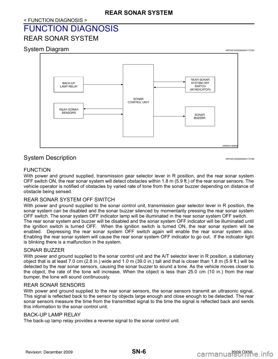
System DiagramINFOID:0000000004173795
System DescriptionINFOID:0000000004173796
FUNCTION
With power and ground supplied, transmission gear selector lever in R position, and the rear sonar system
OFF switch ON, the rear sonar system will detect obstacles within 1.8 m (5.9 ft.) of the rear sonar sensors. The
vehicle operator is notified of obstacles by varied rate of tone from the sonar buzzer depending on distance of
obstacle being sensed.
REAR SONAR SYSTEM OFF SWITCH
With power and ground supplied to the sonar control unit, transmission gear selector lever in R position, the
sonar system can be disabled and the sonar buzzer silenced by momentarily pressing the rear sonar system
OFF switch. The sonar system OFF indicator lamp will be illuminated in the rear sonar system OFF switch.
The rear sonar system and buzzer will be disabled and t he sonar system OFF indicator will be illuminated until
the ignition switch is turned OFF. When the ignition switch is turned ON, the rear sonar system will be
enabled. Depressing the rear sonar system OFF s witch again will enable the rear sonar system also.
Enabling the rear sonar system will cause the rear sonar system OFF indicator to go out. If the indicator light
is blinking there is a malfunction in the system.
SONAR BUZZER
With power and ground supplied to the sonar control unit and the A/T selector lever in R position, a stationary
object that is at least 7.0 cm (2.8 in.) wide and 1.0 m (39. 0 in.) tall and that is closer than 1.8 m (5.9 ft.) will be
detected by the rear sonar sensors, causing the sonar buzzer to sound a tone. As the vehicle moves closer to
the object, the rate of the tone will increase. When the object is less than 25.0 cm (10 in.) from the rear
bumper, the tone will sound continuously.
REAR SONAR SENSORS
With power and ground supplied to the rear sonar sens ors, the sonar sensors transmit an ultrasonic signal.
This signal is reflected back to the sensor by objects large enough and close enough to be detected. The rear
sonar sensors measure the time from the transmitted si gnal to the time the signal is reflected back and sends
this information to the sonar control unit.
BACK-UP LAMP RELAY
The back-up lamp relay provides a reverse signal to the sonar control unit.
AWNIA1499GB
Revision: December 20092009 QX56
Page 3432 of 4171
SN-10
< FUNCTION DIAGNOSIS >
FRONT AND REAR SONAR SYSTEM
FRONT AND REAR SONAR SYSTEM
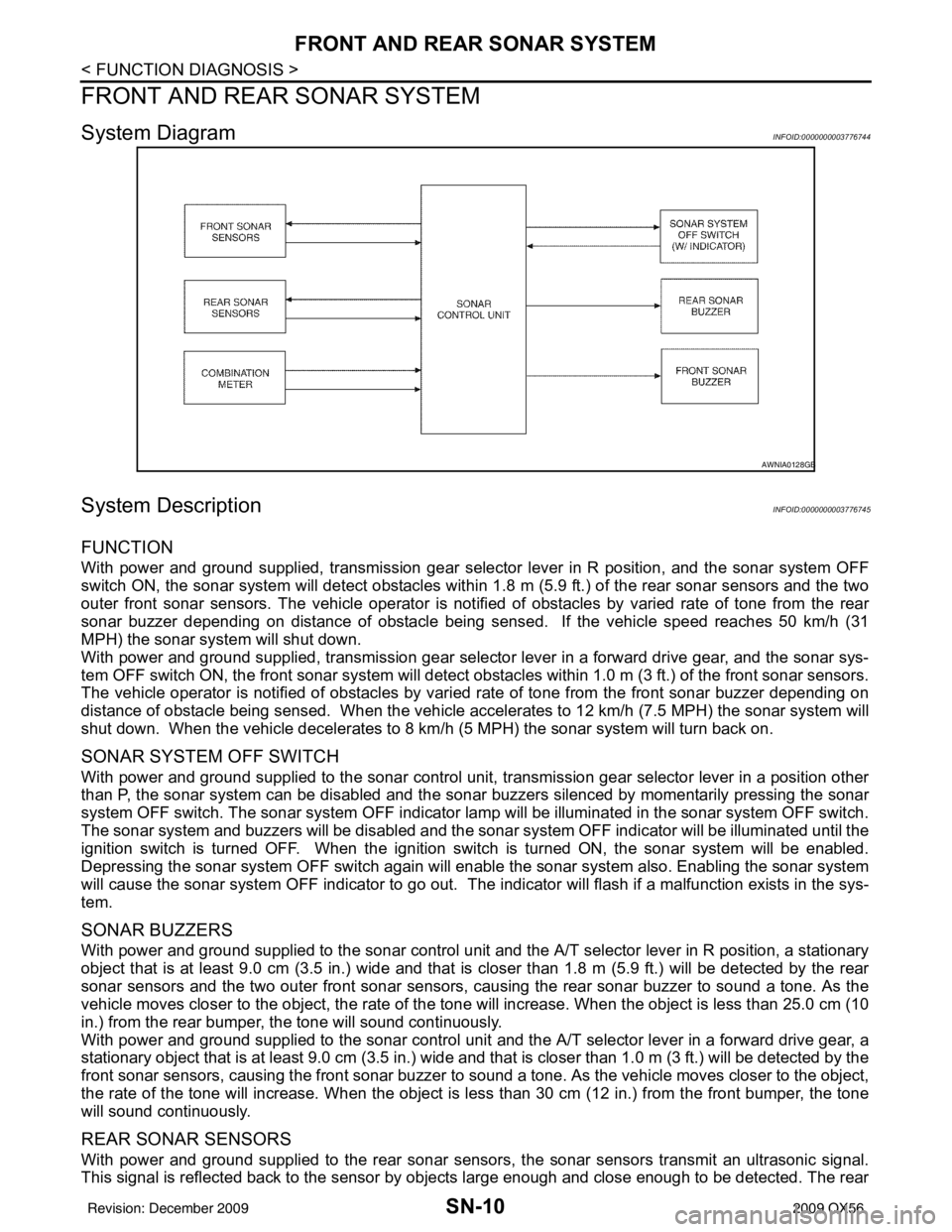
System DiagramINFOID:0000000003776744
System DescriptionINFOID:0000000003776745
FUNCTION
With power and ground supplied, transmission gear selector lever in R position, and the sonar system OFF
switch ON, the sonar system will detect obstacles within 1.8 m (5.9 ft.) of the rear sonar sensors and the two
outer front sonar sensors. The vehicle operator is notif ied of obstacles by varied rate of tone from the rear
sonar buzzer depending on distance of obstacle being sens ed. If the vehicle speed reaches 50 km/h (31
MPH) the sonar syst em will shut down.
With power and ground supplied, transmission gear selector lever in a forward drive gear, and the sonar sys-
tem OFF switch ON, the front sonar system will detect obstacles within 1.0 m (3 ft.) of the front sonar sensors.
The vehicle operator is notified of obstacles by varied rate of tone from the front sonar buzzer depending on
distance of obstacle being sensed. When the vehicle accelerates to 12 km/h (7.5 MPH) the sonar system will
shut down. When the vehicle decelerates to 8 km/h (5 MPH) the sonar system will turn back on.
SONAR SYSTEM OFF SWITCH
With power and ground supplied to the sonar control unit, transmission gear selector lever in a position other
than P, the sonar system can be di sabled and the sonar buzzers silenced by momentarily pressing the sonar
system OFF switch. The sonar system OFF indicator lamp will be illuminated in the sonar system OFF switch.
The sonar system and buzzers will be di sabled and the sonar system OFF indicator will be illuminated until the
ignition switch is turned OFF. When the ignition switch is turned ON, the sonar system will be enabled.
Depressing the sonar system OFF switch again will enabl e the sonar system also. Enabling the sonar system
will cause the sonar system OFF indicator to go out. The indicator will flash if a malfunction exists in the sys-
tem.
SONAR BUZZERS
With power and ground supplied to the sonar control unit and the A/T selector lever in R position, a stationary
object that is at least 9.0 cm (3.5 in.) wide and that is closer than 1.8 m (5.9 ft.) will be detected by the rear
sonar sensors and the two outer front sonar sensors, causing the rear sonar buzzer to sound a tone. As the
vehicle moves closer to the object, the rate of the tone will increase. When the object is less than 25.0 cm (10
in.) from the rear bumper, the tone will sound continuously.
With power and ground supplied to the sonar control unit and the A/T selector lever in a forward drive gear, a
stationary object that is at least 9.0 cm (3.5 in.) wide and that is closer than 1.0 m (3 ft.) will be detected by the
front sonar sensors, causing the front sonar buzzer to sound a tone. As the vehicle moves closer to the object,
the rate of the tone will increase. When the object is less than 30 cm (12 in.) from the front bumper, the tone
will sound continuously.
REAR SONAR SENSORS
With power and ground supplied to the rear sonar sens ors, the sonar sensors transmit an ultrasonic signal.
This signal is reflected back to the sensor by objects large enough and close enough to be detected. The rear
AWNIA0128GB
Revision: December 20092009 QX56
Page 3443 of 4171
SN
SONAR CONTROL UNIT FOR REAR SONAR SYSTEMSN-21
< ECU DIAGNOSIS >
C
DE
F
G H
I
J
K L
M B A
O P
ECU DIAGNOSIS
SONAR CONTROL UNIT FO R REAR SONAR SYSTEM
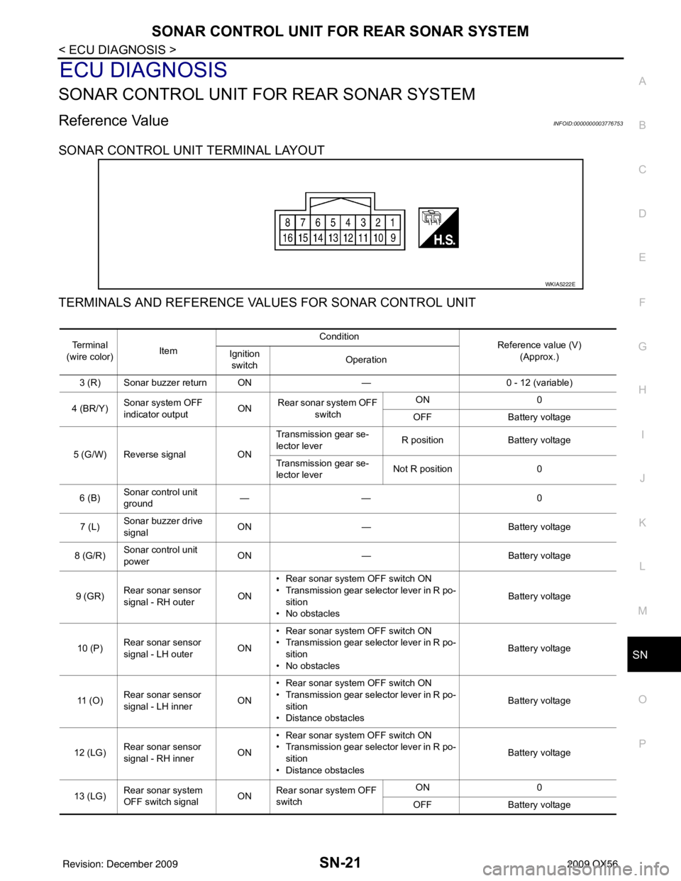
Reference ValueINFOID:0000000003776753
SONAR CONTROL UNIT TERMINAL LAYOUT
TERMINALS AND REFERENCE VA LUES FOR SONAR CONTROL UNIT
WKIA5222E
Te r m i n a l
(wire color) Item Condition
Reference value (V)
(Approx.)
Ignition
switch Operation
3 (R) Sonar buzzer return ON —0 - 12 (variable)
4 (BR/Y) Sonar system OFF
indicator output ON
Rear sonar system OFF
switch ON
0
OFF Battery voltage
5 (G/W) Reverse signal ONTransmission gear se-
lector lever
R position
Battery voltage
Transmission gear se-
lector lever Not R position
0
6 (B) Sonar control unit
ground ——
0
7 (L) Sonar buzzer drive
signal
ON
— Battery voltage
8 (G/R) Sonar control unit
power ON
— Battery voltage
9 (GR) Rear sonar sensor
signal - RH outer
ON• Rear sonar system OFF switch ON
• Transmission gear selector lever in R po-
sition
• No obstacles Battery voltage
10 (P) Rear sonar sensor
signal - LH outer
ON• Rear sonar system OFF switch ON
• Transmission gear selector lever in R po-
sition
• No obstacles Battery voltage
11 ( O ) Rear sonar sensor
signal - LH inner
ON• Rear sonar system OFF switch ON
• Transmission gear selector lever in R po-
sition
• Distance obstacles Battery voltage
12 (LG) Rear sonar sensor
signal - RH inner
ON• Rear sonar system OFF switch ON
• Transmission gear selector lever in R po-
sition
• Distance obstacles Battery voltage
13 (LG) Rear sonar system
OFF switch signal
ONRear sonar system OFF
switch ON
0
OFF Battery voltage
Revision: December 20092009 QX56
Page 3453 of 4171
SN
SONAR CONTROL UNIT FOR FRONT AND REAR SONAR SYSTEMSN-31
< ECU DIAGNOSIS >
C
DE
F
G H
I
J
K L
M B A
O P
SONAR CONTROL UNIT FOR FR ONT AND REAR SONAR SYSTEM
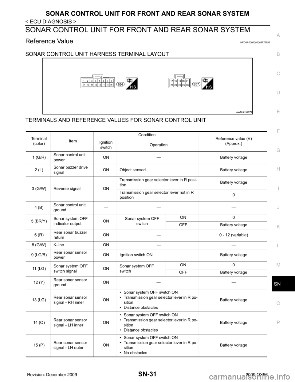
Reference ValueINFOID:0000000003776756
SONAR CONTROL UNIT HARNESS TERMINAL LAYOUT
TERMINALS AND REFERENCE VA LUES FOR SONAR CONTROL UNIT
AWNIA1547ZZ
Te r m i n a l
(color) Item Condition
Reference value (V)
(Approx.)
Ignition
switch Operation
1 (G/R) Sonar control unit
power ON
— Battery voltage
2 (L) Sonar buzzer drive
signal
ON Object sensed
Battery voltage
3 (G/W) Reverse signal ONTransmission gear selector lever in R posi-
tion
Battery voltage
Transmission gear selector lever not in R
position 0
4 (B) Sonar control unit
ground ——
—
5 (BR/Y) Sonar system OFF
indicator output ON
Sonar system OFF
switch ON
0
OFF Battery voltage
6 (R) Rear sonar buzzer
return
ON
— 0 - 12 (variable)
8 (G/W) K-line ON— —
9 (LG/B) Rear sonar sensor
power ON Ignition switch ON
Battery voltage
11 ( L G ) Sonar system OFF
switch signal
ONSonar system OFF
switch ON
0
OFF Battery voltage
12 (Y) Rear sonar sensor
ground ON
— —
13 (LG) Rear sonar sensor
signal - RH inner ON• Sonar system OFF switch ON
• Transmission gear selector lever in R po-
sition
• Distance obstacles Battery voltage
14 (O) Rear sonar sensor
signal - LH inner ON• Sonar system OFF switch ON
• Transmission gear selector lever in R po-
sition
• Distance obstacles Battery voltage
15 (P) Rear sonar sensor
signal - LH outer ON• Sonar system OFF switch ON
• Transmission gear selector lever in R po-
sition
• No obstacles Battery voltage
Revision: December 20092009 QX56
Page 3454 of 4171
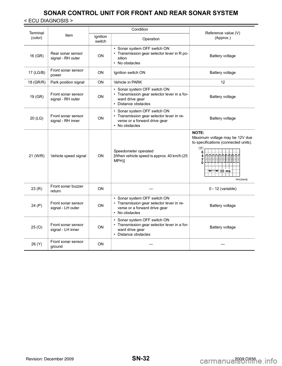
SN-32
< ECU DIAGNOSIS >
SONAR CONTROL UNIT FOR FRONT AND REAR SONAR SYSTEM
16 (GR)Rear sonar sensor
signal - RH outer ON• Sonar system OFF switch ON
• Transmission gear selector lever in R po-
sition
• No obstacles Battery voltage
17 (LG/B) Front sonar sensor
power
ON Ignition switch ON
Battery voltage
18 (GR/R) Park position signal ON Vehicle in PARK 12
19 (GR) Front sonar sensor
signal - RH outer ON• Sonar system OFF switch ON
• Transmission gear selector lever in a for-
ward drive gear
• Distance obstacles Battery voltage
20 (LG) Front sonar sensor
signal - RH inner ON• Sonar system OFF switch ON
• Transmission gear selector lever in re-
verse or a forward drive gear
• No obstacles Battery voltage
21 (W/R) Vehicle speed signal ON Speedometer operated
[When vehicle speed is approx. 40 km/h (25
MPH)]NOTE:
Maximum voltage may be 12V due
to specifications (connected units).
23 (R) Front sonar buzzer
return ON
— 0 - 12 (variable)
24 (P) Front sonar sensor
signal - LH outer
ON• Sonar system OFF switch ON
• Transmission gear selector lever in re-
verse or a forward drive gear
• No obstacles Battery voltage
25 (O) Front sonar sensor
signal - LH inner
ON• Sonar system OFF switch ON
• Transmission gear selector lever in a for-
ward drive gear
• Distance obstacles Battery voltage
26 (Y) Front sonar sensor
ground ON
— —
Te r m i n a l
(color) Item Condition
Reference value (V)
(Approx.)
Ignition
switch Operation
PKIC0643E
Revision: December 20092009 QX56
Page 3467 of 4171
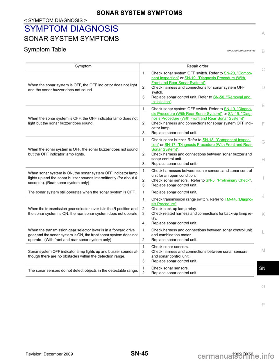
SN
SONAR SYSTEM SYMPTOMSSN-45
< SYMPTOM DIAGNOSIS >
C
DE
F
G H
I
J
K L
M B A
O P
SYMPTOM DIAGNOSIS
SONAR SYSTEM SYMPTOMS
Symptom TableINFOID:0000000003776759
Symptom Repair order
When the sonar system is OFF, the OFF indicator does not light
and the sonar buzzer does not sound. 1. Check sonar system OFF switch. Refer to
SN-20, "
Compo-
nent Inspection" or SN-19, "Diagnosis Procedure (With
Front and Rear Sonar System)".
2. Check harness and connections for sonar system OFF
switch.
3. Replace sonar control unit. Refer to SN-50, "
Removal and
Installation".
When the sonar system is OFF, the OFF indicator lamp does not
light but the sonar buzzer does sound. 1. Check sonar system OFF switch. Refer to
SN-19, "
Diagno-
sis Procedure (With Rear Sonar System)" or SN-19, "Diag-
nosis Procedure (With Front and Rear Sonar System)".
2. Check harness and connections for sonar system OFF indi- cator lamp.
3. Replace sonar control unit.
When the sonar system is OFF, the sonar buzzer does not sound
but the OFF indicator lamp lights. 1. Check sonar buzzer. Refer to
SN-18, "
Component Inspec-
tion" or SN-17, "Diagnosis Procedure (With Front and Rear
Sonar System)".
2. Check harness and connections between sonar buzzer and sonar control unit.
3. Replace sonar control unit.
When sonar system is ON, the sonar system OFF indicator lamp
lights up and the sonar buzzer sounds intermittently (for about 4
seconds). (Rear sonar system only) 1. Check harnesses between sonar sensors and sonar control
unit for an open condition.
2. Check sonar sensors. Refer to SN-5, "
Preliminary Check".
3. Replace sonar control unit.
The sonar system still operates when the sonar system is OFF. 1. Replace sonar control unit.
When the transmission gear selector lever is in the R position and
the sonar system is ON, the rear sonar system does not operate. 1. Check transmission range switch. Refer to
TM-44, "
Diagno-
sis Procedure".
2. Check back-up lamp relay.
3. Check related harness and connections for back-up lamp re- lay.
4. Replace sonar control unit.
When the transmission gear selector lever is in a forward drive
gear and the sonar system is ON, the front sonar system does not
operate. (With front and rear sonar system only) 1. Check harness and connections between sonar control unit
and combination meter.
2. Replace sonar control unit.
Sonar system OFF indicator lamp lights up and buzzer sounds al-
though there are no obstacles within the detection range. 1. Check sonar sensors.
2. Check harness and connections between sonar sensors
and sonar control unit.
3. Replace sonar control unit.
The sonar sensors do not detect objects in the detectable range. 1. Check sonar sensors.
2. Replace sonar control unit.
Revision: December 20092009 QX56