Page 3930 of 4171
TM-282
< DISASSEMBLY AND ASSEMBLY >
ASSEMBLY
b. Measure dimension “L”.
c. Calculate dimension “J”.
2. Measure dimensions “M
1” and “M2” and then calculate dimen-
sion “M”.
a. Place bearing race and needle bearing on oil pump assembly.
b. Measure dimension “M
1”.
c. Measure dimension “M
2”.
“J”: Distance between oil pump fitting surface of
transmission case and needle
bearing mating surface
of front sun gear.
J = K – L
SCIA5352E
SCIA3125E
SCIA3124E
SCIA3126E
SCIA3127E
Revision: December 20092009 QX56
Page 3931 of 4171
ASSEMBLYTM-283
< DISASSEMBLY AND ASSEMBLY >
CEF
G H
I
J
K L
M A
B
TM
N
O P
d. Calculate dimension “M”.
3. Adjust total end play “T
1”.
Select proper thickness of bearing race so that total end play is within specifications.
Assembly (2)INFOID:0000000004187498
1. Install O-ring to oil pump assembly. CAUTION:
Do not reuse O-ring.
Apply ATF to O-ring.
2. Install bearing race to oil pump assembly. CAUTION:
Apply petroleum jelly to bearing race.“M”: Distance between transmission case fitting sur-
face of oil pump and need
le bearing on oil pump.
M = M
1– M2
SCIA3125E
T1 = J – M
Total end play “T
1” : 0.25 - 0.55 mm (0.0098 - 0.0217 in)
Bearing races :Refer to TM-290, "General Specifica-
tion".
SCIA2810E
SCIA5172E
SCIA6529E
Revision: December 20092009 QX56
Page 3932 of 4171

TM-284
< DISASSEMBLY AND ASSEMBLY >
ASSEMBLY
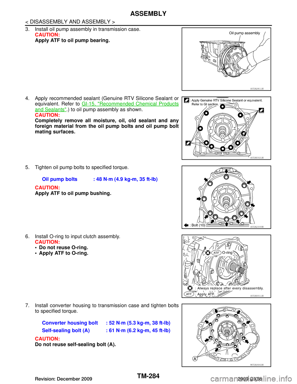
3. Install oil pump assembly in transmission case.CAUTION:
Apply ATF to oil pump bearing.
4. Apply recommended sealant (Genuine RTV Silicone Sealant or equivalent. Refer to GI-15, "Recommended Chemical Products
and Sealants".) to oil pump assembly as shown.
CAUTION:
Completely remove all moistu re, oil, old sealant and any
foreign material from the oil pump bolts and oil pump bolt
mating surfaces.
5. Tighten oil pump bolts to specified torque. CAUTION:
Apply ATF to oil pump bushing.
6. Install O-ring to input clutch assembly. CAUTION:
Do not reuse O-ring.
Apply ATF to O-ring.
7. Install converter housing to transmission case and tighten bolts to specified torque.
CAUTION:
Do not reuse self-sealing bolt (A).
SCIA2811E
SCIA5321E
Oil pump bolts : 48 N·m (4.9 kg-m, 35 ft-lb)
SCIA2300E
SCIA5011E
Converter housing bolt : 52 N·m (5.3 kg-m, 38 ft-lb)
Self-sealing bolt (A) : 61 N·m (6.2 kg-m, 45 ft-lb)
WCIA0662E
Revision: December 20092009 QX56
Page 3933 of 4171
ASSEMBLYTM-285
< DISASSEMBLY AND ASSEMBLY >
CEF
G H
I
J
K L
M A
B
TM
N
O P
8. Make sure that brake band does not close turbine input speed sensor hole.
9. Install control valve with TCM.
a. Connect TCM connector and transmission range switch connec- tor.
b. Install A/T assembly harness connector to control valve with TCM.
c. Connect TCM connectors.
d. Install O-ring to A/T assembly harness connector. CAUTION:
Do not reuse O-ring.
Apply ATF to O-ring.
SCIA5449E
SCIA5450E
SCIA5447E
SCIA5155E
Revision: December 20092009 QX56
Page 3934 of 4171
TM-286
< DISASSEMBLY AND ASSEMBLY >
ASSEMBLY
e. Install A/T fluid temperature sensor 2 to bracket.
f. Install A/T fluid temperature sensor 2 (with bracket) to controlvalve with TCM and tighten bolt to specified torque.
CAUTION:
Adjust bolt hole of bracket to bolt hole of control valve.
g. Install control valve with TCM in transmission case. 1. : Brake band
CAUTION:
Make sure that input speed sensor is securely installed
into input speed sensor hole (A).
Hang down output speed sen sor harness toward outside
so as not to disturb installati on of control valve with TCM.
Adjust A/T assembly harness co nnector of control valve
with TCM to terminal hole of transmission case.
Assemble it so that manual valve cutout is engaged with manual plate projection.
SCIA5264E
Bracket bolt : 7.9 N·m (0.81 kg-m, 70 in-lb)
SCIA5253E
JSDIA1318ZZ
SCIA5035E
Revision: December 20092009 QX56
Page 3936 of 4171
TM-288
< DISASSEMBLY AND ASSEMBLY >
ASSEMBLY
15. Install snap ring to A/T assembly harness connector.
16. Install magnets in oil pan.
17. Install oil pan to transmission case. Refer to TM-201, "Oil Pan"
.
18. Install torque converter.
a. Pour ATF into torque converter. NOTE:
Approximately 2 liters (2-1/8 US qt. 1-3/4 Imp qt) of fluid is
required for a new torque converter.
When reusing old torque converter, add the same amount of
fluid as was drained.
b. Install torque converter while aligning notches of torque con- verter with notches of oil pump.
CAUTION:
Install torque converte r while rotating it.
SCIA5300E
SCIA5200E
SAT428DA
SCIA5010E
Revision: December 20092009 QX56
Page 3938 of 4171

TM-290
< SERVICE DATA AND SPECIFICATIONS (SDS)
SERVICE DATA AND SPECIFICATIONS (SDS)
SERVICE DATA AND SPECIFICATIONS (SDS)
SERVICE DATA AND SPECIFICATIONS (SDS)
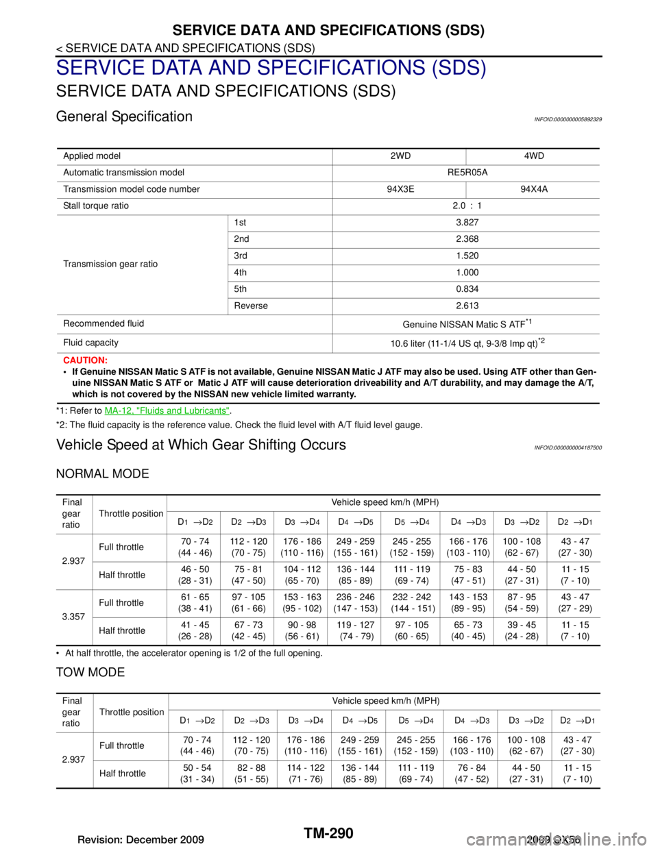
General SpecificationINFOID:0000000005892329
*1: Refer to MA-12, "Fluids and Lubricants".
*2: The fluid capacity is the reference value. Check the fluid level with A/T fluid level gauge.
Vehicle Speed at Which Gear Shifting OccursINFOID:0000000004187500
NORMAL MODE
At half throttle, the accelerator opening is 1/2 of the full opening.
TOW MODE
Applied model 2WD 4WD
Automatic transmission model RE5R05A
Transmission model code number 94X3E 94X4A
Stall torque ratio 2.0 : 1
Transmission gear ratio 1st 3.827
2nd 2.368
3rd 1.520
4th 1.000
5th 0.834
Reverse 2.613
Recommended fluid Genuine NISSAN Matic S ATF
*1
Fluid capacity10.6 liter (11-1/4 US qt, 9-3/8 Imp qt)*2
CAUTION:
If Genuine NISSAN Matic S ATF is not available, Genuine NISSAN Matic J ATF may also be used. Using ATF other than Gen-
uine NISSAN Matic S ATF or Matic J ATF will cause deterioration driveability and A/T durability, and may damage the A/T,
which is not covered by the NISSAN new vehicle limited warranty.
Final
gear
ratio Throttle position
Vehicle speed km/h (MPH)
D
1 → D2D2 → D3D3 → D4D4 → D5D5 → D4D4 → D3D3 → D2D2 → D1
2.937 Full throttle
70 - 74
(44 - 46) 112 - 120
(70 - 75) 176 - 186
(110 - 116) 249 - 259
(155 - 161) 245 - 255
(152 - 159) 166 - 176
(103 - 110) 100 - 108
(62 - 67) 43 - 47
(27 - 30)
Half throttle 46 - 50
(28 - 31) 75 - 81
(47 - 50) 104 - 112
(65 - 70) 136 - 144
(85 - 89) 111 - 11 9
(69 - 74) 75 - 83
(47 - 51) 44 - 50
(27 - 31) 11 - 1 5
(7 - 10)
3.357 Full throttle
61 - 65
(38 - 41) 97 - 105
(61 - 66) 153 - 163
(95 - 102) 236 - 246
(147 - 153) 232 - 242
(144 - 151) 143 - 153
(89 - 95) 87 - 95
(54 - 59) 43 - 47
(27 - 29)
Half throttle 41 - 45
(26 - 28) 67 - 73
(42 - 45) 90 - 98
(56 - 61) 119 - 127
(74 - 79) 97 - 105
(60 - 65) 65 - 73
(40 - 45) 39 - 45
(24 - 28) 11 - 1 5
(7 - 10)
Final
gear
ratio Throttle position Vehicle speed km/h (MPH)
D
1 → D2D2 → D3D3 → D4D4 → D5D5 → D4D4 → D3D3 → D2D2 → D1
2.937 Full throttle
70 - 74
(44 - 46) 112 - 120
(70 - 75) 176 - 186
(110 - 116) 249 - 259
(155 - 161) 245 - 255
(152 - 159) 166 - 176
(103 - 110) 100 - 108
(62 - 67) 43 - 47
(27 - 30)
Half throttle 50 - 54
(31 - 34) 82 - 88
(51 - 55) 114 - 122
(71 - 76) 136 - 144
(85 - 89) 111 - 11 9
(69 - 74) 76 - 84
(47 - 52) 44 - 50
(27 - 31) 11 - 1 5
(7 - 10)
Revision: December 20092009 QX56