Page 209 of 534

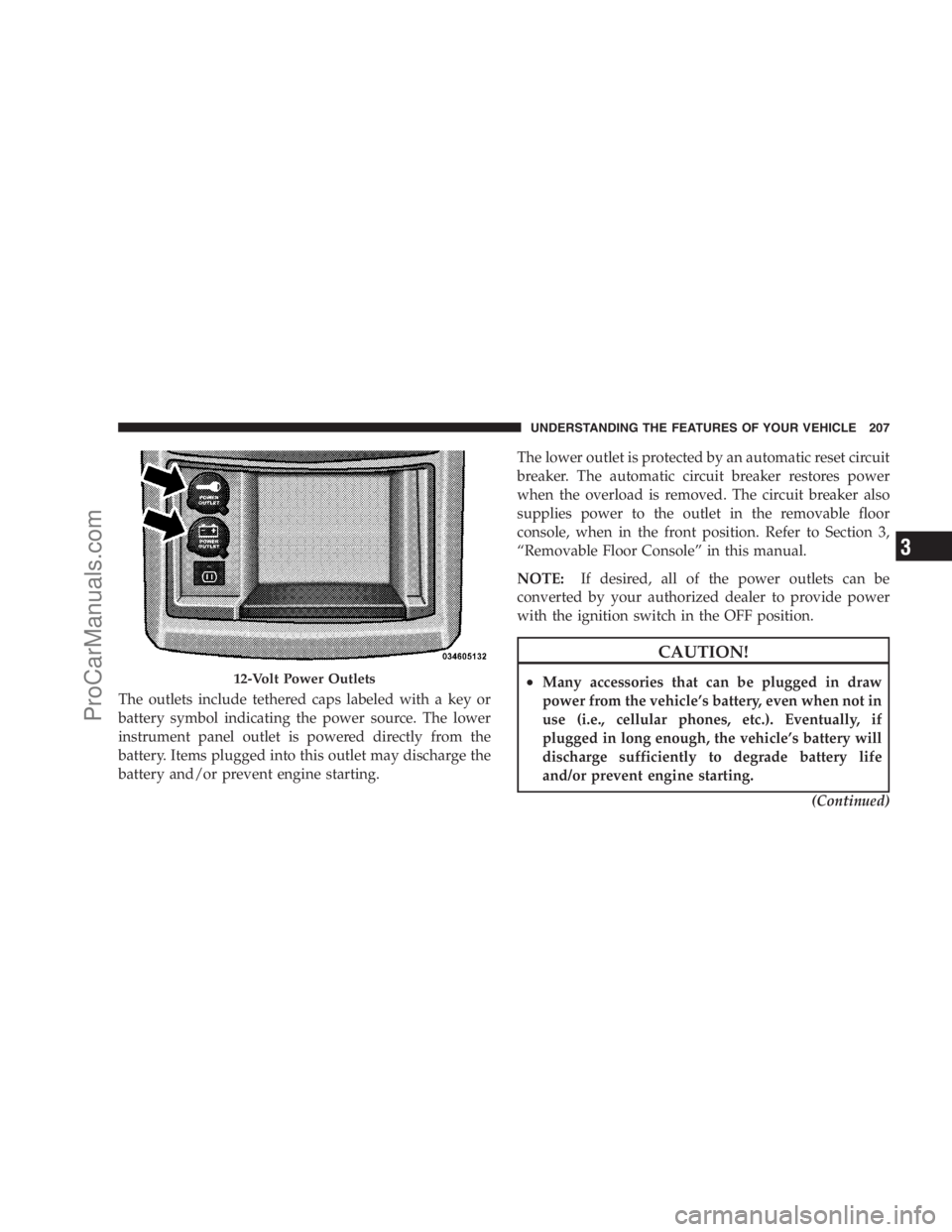
The outlets include tethered caps labeled with a key or
battery symbol indicating the power source. The lower
instrument panel outlet is powered directly from the
battery. Items plugged into this outlet may discharge the
battery and/or prevent engine starting.The lower outlet is protected by an automatic reset circuit
breaker. The automatic circuit breaker restores power
when the overload is removed. The circuit breaker also
supplies power to the outlet in the removable floor
console, when in the front position. Refer to Section 3,
“Removable Floor Console” in this manual.
NOTE:If desired, all of the power outlets can be
converted by your authorized dealer to provide power
with the ignition switch in the OFF position.
CAUTION!
•Many accessories that can be plugged in draw
power from the vehicle’s battery, even when not in
use (i.e., cellular phones, etc.). Eventually, if
plugged in long enough, the vehicle’s battery will
discharge sufficiently to degrade battery life
and/or prevent engine starting.
(Continued)12-Volt Power Outlets
UNDERSTANDING THE FEATURES OF YOUR VEHICLE 207
3
ProCarManuals.com
Page 210 of 534

CAUTION! (Continued)
•Accessories that draw higher power (i.e., coolers,
vacuum cleaners, lights, etc.), will degrade the
battery even more quickly. Only use these inter-
mittently and with greater caution.
•After the use of high power draw accessories, or
long periods of the vehicle not being started (with
accessories still plugged in), the vehicle must be
driven a sufficient length of time to allow the
alternator to recharge the vehicle’s battery.
•Power outlets are designed for accessory plugs
only. Do not hang any type of accessory or acces-
sory bracket from the plug. Improper use of the
power outlet can cause damage.
POWER INVERTER — IF EQUIPPED
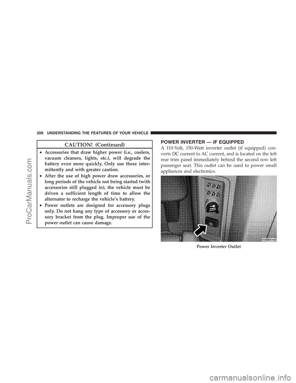
A 110-Volt, 150-Watt inverter outlet (if equipped) con-
verts DC current to AC current, and is located on the left
rear trim panel immediately behind the second row left
passenger seat. This outlet can be used to power small
appliances and electronics.
Power Inverter Outlet
208 UNDERSTANDING THE FEATURES OF YOUR VEHICLE
ProCarManuals.com
Page 253 of 534

NOTE:Magnetic and battery powered devices, (such as
cell phones, IPOD’s, radar detectors, PDA’s and laptops)
should be kept away from the top of the instrument
panel. This is where the compass module is located and
such devices may interfere and cause false compass
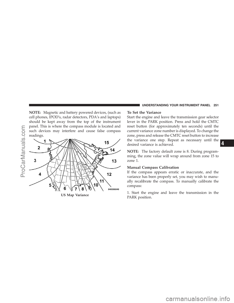
readings.To Set the Variance
Start the engine and leave the transmission gear selector
lever in the PARK position. Press and hold the CMTC
reset button (for approximately ten seconds) until the
current variance zone number is displayed. To change the
zone, press and release the CMTC reset button to increase
the variance one step. Repeat as necessary until the
desired variance is achieved.
NOTE:The factory default zone is 8. During program-
ming, the zone value will wrap around from zone 15 to
zone 1.
Manual Compass Calibration
If the compass appears erratic or inaccurate, and the
variance has been properly set, you may wish to manu-
ally recalibrate the compass. To manually calibrate the
compass:
1. Start the engine and leave the transmission in the
PARK position.
US Map Variance
UNDERSTANDING YOUR INSTRUMENT PANEL 251
4
ProCarManuals.com
Page 256 of 534
Steering Wheel EVIC Compass/Temp
Control Button, as it appears on the
right side of the steering column.
Press and release the Compass/Temperature
button to for instant access to the Compass/
Temperature screens.
Press this button to RESET Trip Functions and
change Personal Settings.
EVIC Displays
When the appropriate conditions exist, the EVIC displays
the following messages:
•Door(s) Ajar (with a single chime, if vehicle is in
motion)
•Liftgate Ajar (chime will sound when vehicle starts
moving)
•Hood Ajar (if equipped with hood switch)
•Check TPM System (refer to “Tire Pressure Monitoring
System” in Section 5 of this manual)
•Turn Signal On
•RKE Battery Low
•LOW WASHER FLUID
•Oil Change Required
•Left Front Turn Signal Light Out
•Left Rear Turn Signal Light Out
•Right Front Turn Signal Light Out
254 UNDERSTANDING YOUR INSTRUMENT PANEL
ProCarManuals.com
Page 289 of 534

UCI supports Mini, 4G, Photo, Nano, 5G iPod�and
iPhone�devices. Some iPod�software versions may not
fully support the UCI features. Please visit Apple’s
website for software updates.
NOTE:
•If the radio has a USB port, connecting an iPod�to this
port does not play the media. For playing an iPod�,
use the separate 16–pin connector port (in the glove
compartment on some vehicles).
•Connecting an iPod�to the AUX port located in the
radio faceplate, plays media, but does not use the UCI
feature to control the connected device.
Connecting The iPod�
Use the optional connection cable to connect an iPod�to
the vehicle’s 16–pin connector port (which is located in
the glove compartment on some vehicles). Once the
iPod�is connected and synchronized to the vehicle’s UCIsystem (iPod�may take a few seconds to connect), the
iPod�starts charging and is ready for use by pressing
radio switches, as described below.
NOTE:
•You may have to remove the connector pin protection
cap from the 16–pin connector port, prior to connect-
ing the cable.
•If the iPod�battery is completely discharged, it may
not communicate with the UCI system until a mini-
mum charge is attained. Leaving the iPod�connected
to the UCI system may charge it to the required level.
Using This Feature
By using the optional connection cable to connect an
iPod�to the vehicle’s UCI 16–pin connector port:
•The iPod�audio can be played on the vehicle’s sound
system, providing metadata (Artist, track title, album,
etc.) information on the radio display.
UNDERSTANDING YOUR INSTRUMENT PANEL 287
4
ProCarManuals.com
Page 290 of 534

•The iPod�can be controlled using the radio buttons to
Play, Browse, and List the iPod�contents.
•The iPod�battery charges when plugged into the UCI
connector.
Controlling The iPod�Using Radio Buttons
To get into the UCI (iPod�) mode and access a connected
iPod�, press the ‘AUX’ button on the radio faceplate.
Once in the UCI (iPod�) mode, iPod�audio tracks (if
available from iPod�) start playing over the vehicle’s
audio system.
Play Mode
When switched to UCI mode, the iPod�automatically
starts Play mode. In Play mode, you may use the
following buttons on the radio faceplate to control the
iPod�and display data:
•Use the TUNE control knob to select the next or
previous track.
•Turning it clockwise (forward) by one click, while
playing a track, skips to the next track.
•Turning it counterclockwise (backward) by one
click, during the first two seconds of the track, will
jump to the previous track in the list. Turning this
button at any other time in the track, will jump to
the beginning of the current track.
•Jump backward in the current track by pressing and
holding the <
button long enough will take you to the beginning
of the current track.
•Jump forward in the current track by pressing and
holding theFF>> button.
•A single press backward <> will
jump backward or forward respectively, for five
seconds.
288 UNDERSTANDING YOUR INSTRUMENT PANEL
ProCarManuals.com
Page 299 of 534

SIRIUS BACKSEAT TV™ — IF EQUIPPED
Satellite video uses direct satellite receiver broadcasting
technology to provide streaming video. The subscription
service provider is SIRIUS Satellite Radio. SIRIUS Back-
seat TV™ offers three video channels for family enter-
tainment, directly from its satellites and broadcasting
studios.
NOTE:SIRIUS service is not available in Hawaii and
has limited coverage in Alaska.
Refer to your Video Entertainment System (VES)™, RER
Navigation or REN Multimedia User Manuals for de-
tailed operating instructions.
VIDEO ENTERTAINMENT SYSTEM (VES)™ — IF
EQUIPPED
The optional Video Entertainment System (VES)™ is
available with:
•One or two video screens
•Additional single-disc DVD player with two-screen
system
•Battery-powered two-channel remote control
•Two remote headphones
•Integrated remote storage in either screen location
•Three different medias can be played simultaneously
(Cabin speakers and Headphone Channels 1 and 2)
•Easy menu-driven functions on touch-screen radios
•Video and audio input jacks available in rear seating
area
UNDERSTANDING YOUR INSTRUMENT PANEL 297
4
ProCarManuals.com
Page 328 of 534

WARNING! (Continued)
•Do not attempt to push or tow your vehicle to get
it started. Vehicles equipped with an automatic
transaxle cannot be started this way. Unburned
fuel could enter the catalytic converter and once
the engine has started, ignite and damage the
converter and vehicle.
•If the vehicle has a discharged battery, booster
cables may be used to obtain a start from a booster
battery or the battery in another vehicle. This type
of start can be dangerous if done improperly. Refer
to “Jump Starting” in Section 6 of this manual.
If the engine fails to start after you have followed the
“Normal Starting” procedure, it may be flooded. Push
the accelerator pedal all the way to the floor and hold it
there while cranking the engine. This should clear any
excess fuel in case the engine is flooded.
CAUTION!
To prevent damage to the starter, DO NOT crank the
engine for more than 15–second intervals at one time.
Wait 10 to 15 seconds before trying again.
If the engine has been flooded, it may start to run, but not
have enough power to continue running when the key is
released. If this occurs, continue cranking with the accel-
erator pedal pushed all the way to the floor. Release the
accelerator pedal and the key once the engine is running
smoothly.
If the engine shows no sign of starting after two 15–
second intervals of cranking with the accelerator pedal
held to the floor, the “Normal Starting” procedure should
be repeated.
326 STARTING AND OPERATING
ProCarManuals.com