2009 CHERY TIGGO oil pressure
[x] Cancel search: oil pressurePage 1527 of 1903
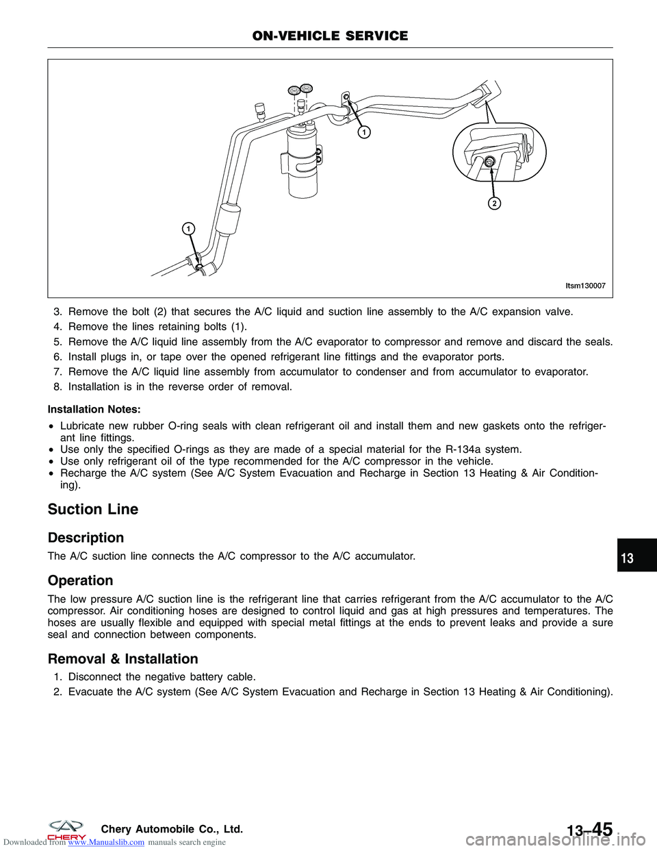
Downloaded from www.Manualslib.com manuals search engine 3. Remove the bolt (2) that secures the A/C liquid and suction line assembly to the A/C expansion valve.
4. Remove the lines retaining bolts (1).
5. Remove the A/C liquid line assembly from the A/C evaporator to compressor and remove and discard the seals.
6. Install plugs in, or tape over the opened refrigerant line fittings and the evaporator ports.
7. Remove the A/C liquid line assembly from accumulator to condenser and from accumulator to evaporator.
8. Installation is in the reverse order of removal.
Installation Notes:
• Lubricate new rubber O-ring seals with clean refrigerant oil and install them and new gaskets onto the refriger-
ant line fittings.
• Use only the specified O-rings as they are made of a special material for the R-134a system.
• Use only refrigerant oil of the type recommended for the A/C compressor in the vehicle.
• Recharge the A/C system (See A/C System Evacuation and Recharge in Section 13 Heating & Air Condition-
ing).
Suction Line
Description
The A/C suction line connects the A/C compressor to the A/C accumulator.
Operation
The low pressure A/C suction line is the refrigerant line that carries refrigerant from the A/C accumulator to the A/C
compressor. Air conditioning hoses are designed to control liquid and gas at high pressures and temperatures. The
hoses are usually flexible and equipped with special metal fittings at the ends to prevent leaks and provide a sure
seal and connection between components.
Removal & Installation
1. Disconnect the negative battery cable.
2. Evacuate the A/C system (See A/C System Evacuation and Recharge in Section 13 Heating & Air Conditioning).
ON-VEHICLE SERVICE
LTSM130007
13
13–45Chery Automobile Co., Ltd.
Page 1603 of 1903
Downloaded from www.Manualslib.com manuals search engine CHIME
Description
The chime is located in the Instrument Cluster (IC). The chime warning system is an audible notification to the driver.
The chime warning system is designed to alert the driver of a vehicle problem or condition.
Operation
The Instrument Cluster (IC) uses hard wired inputs from various sensors and switches to activate the chime. The
sensors and switches are located throughout the vehicle. The following conditions will cause the chime to operate:
•Turn signal on
• Hazard warning flashers on
• Seat belt unbuckled
• Low fuel level
• Low oil pressure
• Low brake fluid level
• Doors unlocked
CHIME
15
15–19Chery Automobile Co., Ltd.
Page 1636 of 1903
Downloaded from www.Manualslib.com manuals search engine INSTRUMENT CLUSTER
Description
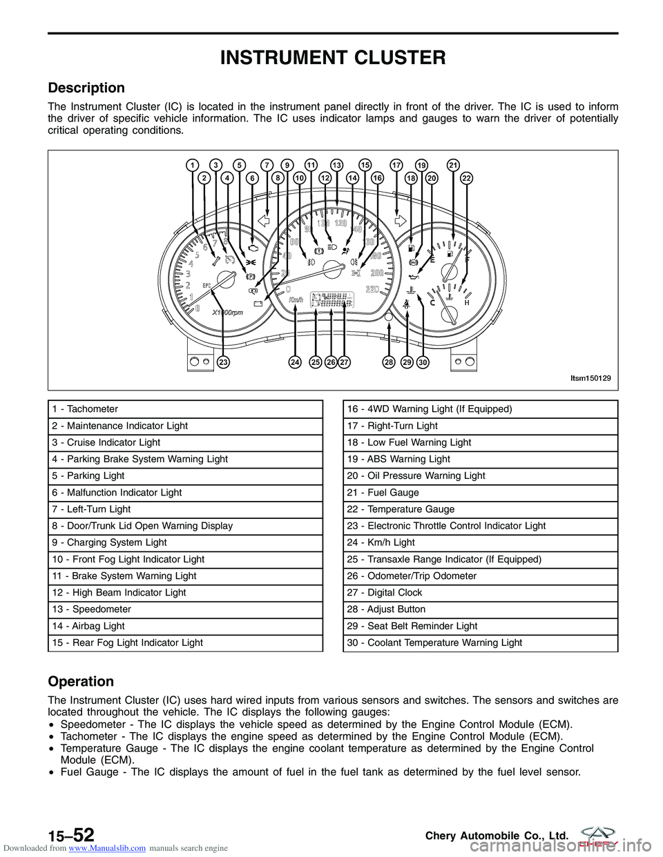
The Instrument Cluster (IC) is located in the instrument panel directly in front of the driver. The IC is used to inform
the driver of specific vehicle information. The IC uses indicator lamps and gauges to warn the driver of potentially
critical operating conditions.
Operation
The Instrument Cluster (IC) uses hard wired inputs from various sensors and switches. The sensors and switches are
located throughout the vehicle. The IC displays the following gauges:
•Speedometer - The IC displays the vehicle speed as determined by the Engine Control Module (ECM).
• Tachometer - The IC displays the engine speed as determined by the Engine Control Module (ECM).
• Temperature Gauge - The IC displays the engine coolant temperature as determined by the Engine Control
Module (ECM).
• Fuel Gauge - The IC displays the amount of fuel in the fuel tank as determined by the fuel level sensor.
1 - Tachometer
2 - Maintenance Indicator Light
3 - Cruise Indicator Light
4 - Parking Brake System Warning Light
5 - Parking Light
6 - Malfunction Indicator Light
7 - Left-Turn Light
8 - Door/Trunk Lid Open Warning Display
9 - Charging System Light
10 - Front Fog Light Indicator Light
11 - Brake System Warning Light
12 - High Beam Indicator Light
13 - Speedometer
14 - Airbag Light
15 - Rear Fog Light Indicator Light16 - 4WD Warning Light (If Equipped)
17 - Right-Turn Light
18 - Low Fuel Warning Light
19 - ABS Warning Light
20 - Oil Pressure Warning Light
21 - Fuel Gauge
22 - Temperature Gauge
23 - Electronic Throttle Control Indicator Light
24 - Km/h Light
25 - Transaxle Range Indicator (If Equipped)
26 - Odometer/Trip Odometer
27 - Digital Clock
28 - Adjust Button
29 - Seat Belt Reminder Light
30 - Coolant Temperature Warning Light
LTSM150129
15–52Chery Automobile Co., Ltd.
Page 1646 of 1903
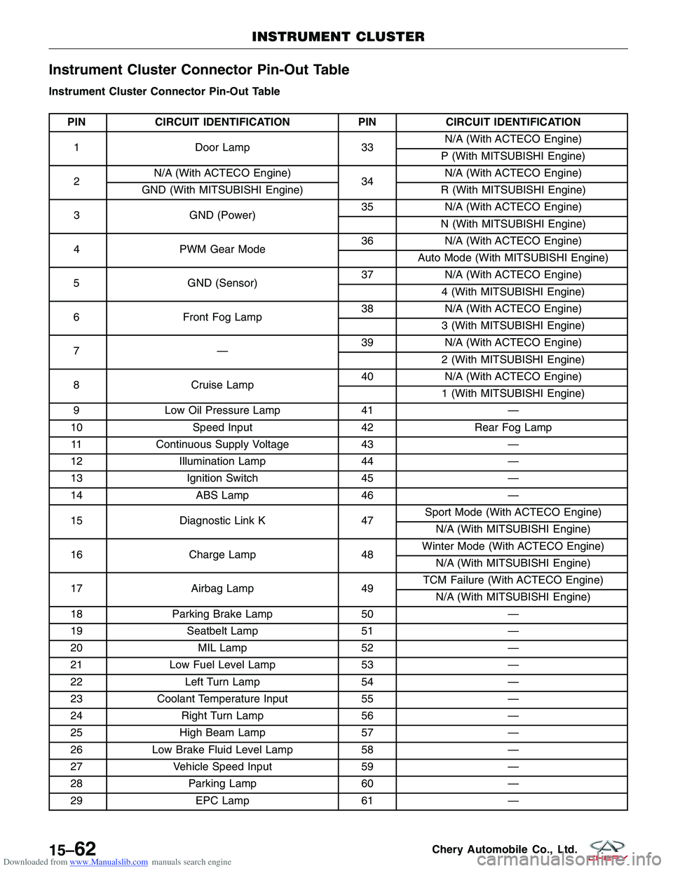
Downloaded from www.Manualslib.com manuals search engine Instrument Cluster Connector Pin-Out Table
Instrument Cluster Connector Pin-Out Table
PINCIRCUIT IDENTIFICATION PINCIRCUIT IDENTIFICATION
1 Door Lamp 33N/A (With ACTECO Engine)
P (With MITSUBISHI Engine)
2 N/A (With ACTECO Engine)
34N/A (With ACTECO Engine)
GND (With MITSUBISHI Engine) R (With MITSUBISHI Engine)
3 GND (Power) 35
N/A (With ACTECO Engine)
N (With MITSUBISHI Engine)
4 PWM Gear Mode 36
N/A (With ACTECO Engine)
Auto Mode (With MITSUBISHI Engine)
5 GND (Sensor) 37
N/A (With ACTECO Engine)
4 (With MITSUBISHI Engine)
6 Front Fog Lamp 38
N/A (With ACTECO Engine)
3 (With MITSUBISHI Engine)
7— 39
N/A (With ACTECO Engine)
2 (With MITSUBISHI Engine)
8 Cruise Lamp 40
N/A (With ACTECO Engine)
1 (With MITSUBISHI Engine)
9 Low Oil Pressure Lamp 41—
10 Speed Input 42Rear Fog Lamp
11 Continuous Supply Voltage 43—
12 Illumination Lamp 44—
13 Ignition Switch 45—
14 ABS Lamp 46—
15 Diagnostic Link K 47Sport Mode (With ACTECO Engine)
N/A (With MITSUBISHI Engine)
16 Charge Lamp 48Winter Mode (With ACTECO Engine)
N/A (With MITSUBISHI Engine)
17 Airbag Lamp 49TCM Failure (With ACTECO Engine)
N/A (With MITSUBISHI Engine)
18 Parking Brake Lamp 50—
19 Seatbelt Lamp 51—
20 MIL Lamp 52—
21 Low Fuel Level Lamp 53—
22 Left Turn Lamp 54—
23 Coolant Temperature Input 55—
24 Right Turn Lamp 56—
25 High Beam Lamp 57—
26 Low Brake Fluid Level Lamp 58—
27 Vehicle Speed Input 59—
28 Parking Lamp 60—
29 EPC Lamp 61—
INSTRUMENT CLUSTER
15–62Chery Automobile Co., Ltd.
Page 1875 of 1903
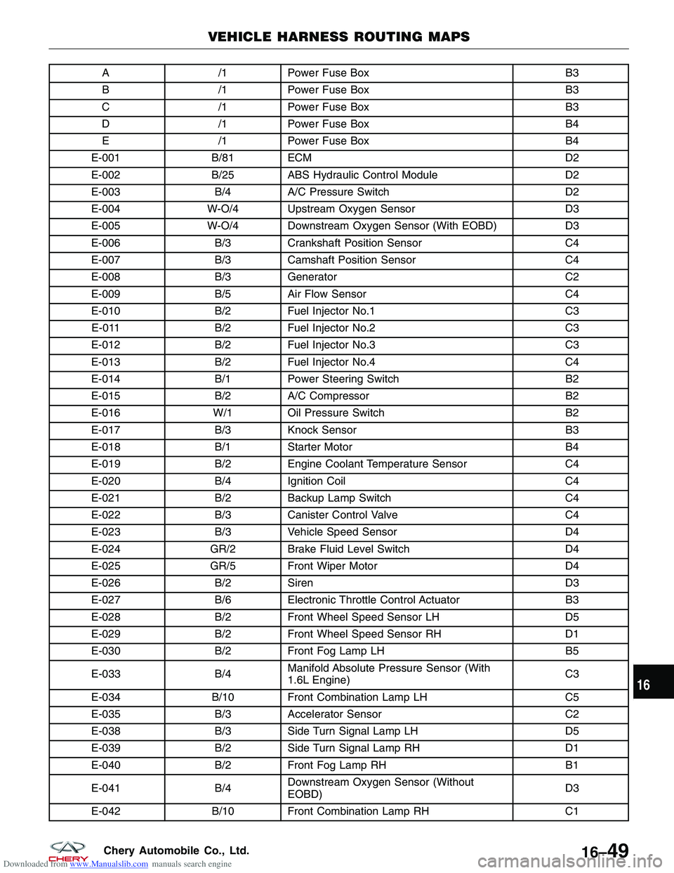
Downloaded from www.Manualslib.com manuals search engine A/1Power Fuse Box B3
B /1Power Fuse Box B3
C /1Power Fuse Box B3
D /1Power Fuse Box B4
E /1Power Fuse Box B4
E-001 B/81 ECM D2
E-002 B/25 ABS Hydraulic Control Module D2
E-003 B/4A/C Pressure Switch D2
E-004 W-O/4 Upstream Oxygen Sensor D3
E-005 W-O/4 Downstream Oxygen Sensor (With EOBD) D3
E-006 B/3Crankshaft Position Sensor C4
E-007 B/3Camshaft Position Sensor C4
E-008 B/3Generator C2
E-009 B/5Air Flow Sensor C4
E-010 B/2Fuel Injector No.1 C3
E-011 B/2Fuel Injector No.2 C3
E-012 B/2Fuel Injector No.3 C3
E-013 B/2Fuel Injector No.4 C4
E-014 B/1Power Steering Switch B2
E-015 B/2A/C Compressor B2
E-016 W/1 Oil Pressure Switch B2
E-017 B/3Knock Sensor B3
E-018 B/1Starter Motor B4
E-019 B/2Engine Coolant Temperature Sensor C4
E-020 B/4Ignition Coil C4
E-021 B/2Backup Lamp Switch C4
E-022 B/3Canister Control Valve C4
E-023 B/3Vehicle Speed Sensor D4
E-024 GR/2 Brake Fluid Level Switch D4
E-025 GR/5 Front Wiper Motor D4
E-026 B/2Siren D3
E-027 B/6Electronic Throttle Control Actuator B3
E-028 B/2Front Wheel Speed Sensor LH D5
E-029 B/2Front Wheel Speed Sensor RH D1
E-030 B/2Front Fog Lamp LH B5
E-033 B/4Manifold Absolute Pressure Sensor (With
1.6L Engine) C3
E-034 B/10 Front Combination Lamp LH C5
E-035 B/3Accelerator Sensor C2
E-038 B/3Side Turn Signal Lamp LH D5
E-039 B/2Side Turn Signal Lamp RH D1
E-040 B/2Front Fog Lamp RH B1
E-041 B/4Downstream Oxygen Sensor (Without
EOBD) D3
E-042 B/10 Front Combination Lamp RH C1
VEHICLE HARNESS ROUTING MAPS
16
16–49Chery Automobile Co., Ltd.
Page 1878 of 1903
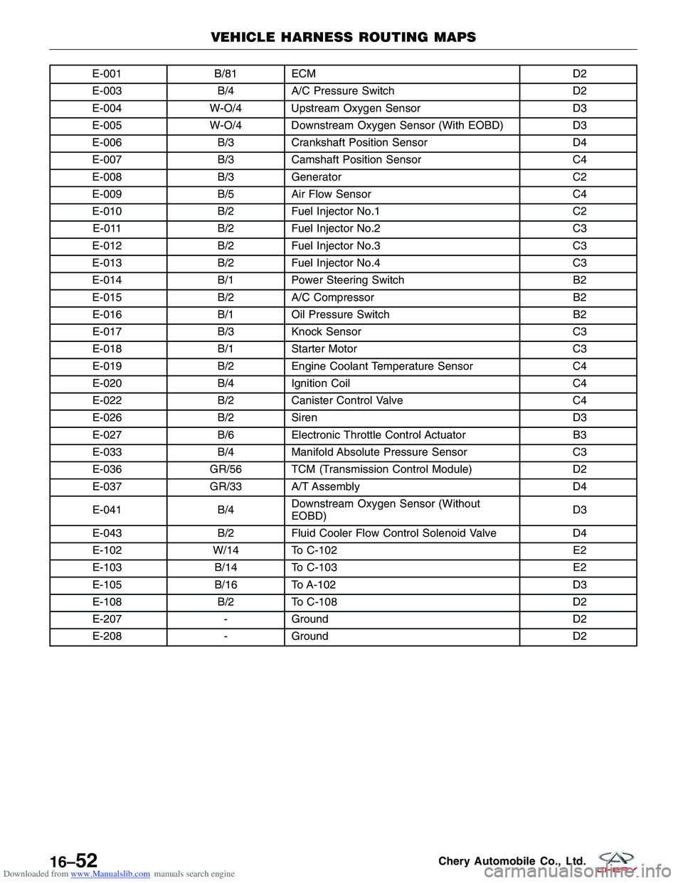
Downloaded from www.Manualslib.com manuals search engine E-001B/81 ECM D2
E-003 B/4A/C Pressure Switch D2
E-004 W-O/4 Upstream Oxygen Sensor D3
E-005 W-O/4 Downstream Oxygen Sensor (With EOBD) D3
E-006 B/3Crankshaft Position Sensor D4
E-007 B/3Camshaft Position Sensor C4
E-008 B/3Generator C2
E-009 B/5Air Flow Sensor C4
E-010 B/2Fuel Injector No.1 C2
E-011 B/2Fuel Injector No.2 C3
E-012 B/2Fuel Injector No.3 C3
E-013 B/2Fuel Injector No.4 C3
E-014 B/1Power Steering Switch B2
E-015 B/2A/C Compressor B2
E-016 B/1Oil Pressure Switch B2
E-017 B/3Knock Sensor C3
E-018 B/1Starter Motor C3
E-019 B/2Engine Coolant Temperature Sensor C4
E-020 B/4Ignition Coil C4
E-022 B/2Canister Control Valve C4
E-026 B/2Siren D3
E-027 B/6Electronic Throttle Control Actuator B3
E-033 B/4Manifold Absolute Pressure Sensor C3
E-036 GR/56 TCM (Transmission Control Module) D2
E-037 GR/33 A/T Assembly D4
E-041 B/4Downstream Oxygen Sensor (Without
EOBD) D3
E-043 B/2Fluid Cooler Flow Control Solenoid Valve D4
E-102 W/14 To C-102 E2
E-103 B/14 To C-103 E2
E-105 B/16 To A-102 D3
E-108 B/2To C-108 D2
E-207 -Ground D2
E-208 -Ground D2
VEHICLE HARNESS ROUTING MAPS
16–52Chery Automobile Co., Ltd.
Page 1880 of 1903
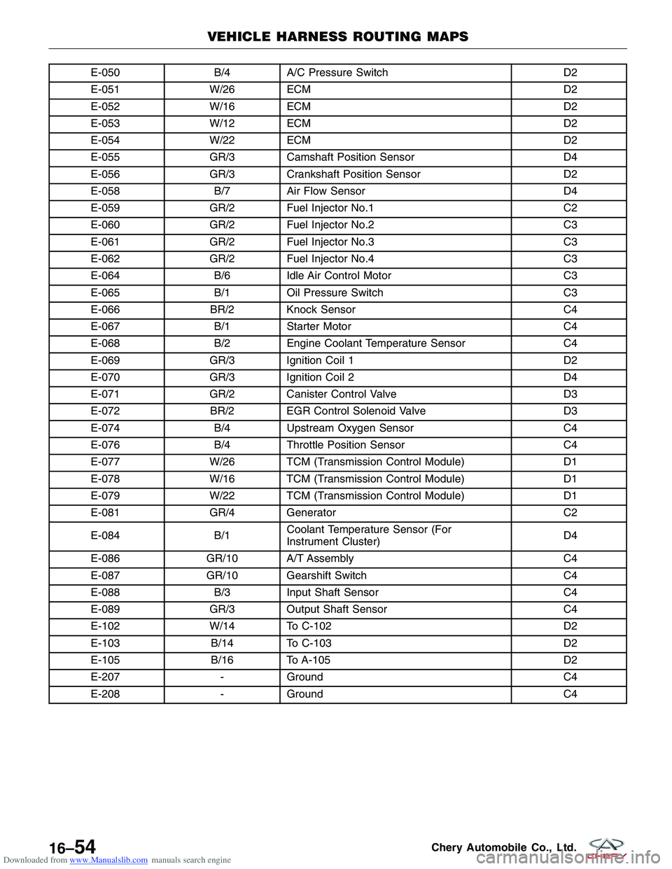
Downloaded from www.Manualslib.com manuals search engine E-050B/4A/C Pressure Switch D2
E-051 W/26 ECM D2
E-052 W/16 ECM D2
E-053 W/12 ECM D2
E-054 W/22 ECM D2
E-055 GR/3 Camshaft Position Sensor D4
E-056 GR/3 Crankshaft Position Sensor D2
E-058 B/7Air Flow Sensor D4
E-059 GR/2 Fuel Injector No.1 C2
E-060 GR/2 Fuel Injector No.2 C3
E-061 GR/2 Fuel Injector No.3 C3
E-062 GR/2 Fuel Injector No.4 C3
E-064 B/6Idle Air Control Motor C3
E-065 B/1Oil Pressure Switch C3
E-066 BR/2 Knock Sensor C4
E-067 B/1Starter Motor C4
E-068 B/2Engine Coolant Temperature Sensor C4
E-069 GR/3 Ignition Coil 1 D2
E-070 GR/3 Ignition Coil 2 D4
E-071 GR/2 Canister Control Valve D3
E-072 BR/2 EGR Control Solenoid Valve D3
E-074 B/4Upstream Oxygen Sensor C4
E-076 B/4Throttle Position Sensor C4
E-077 W/26 TCM (Transmission Control Module) D1
E-078 W/16 TCM (Transmission Control Module) D1
E-079 W/22 TCM (Transmission Control Module) D1
E-081 GR/4 Generator C2
E-084 B/1Coolant Temperature Sensor (For
Instrument Cluster) D4
E-086 GR/10 A/T Assembly C4
E-087 GR/10 Gearshift Switch C4
E-088 B/3Input Shaft Sensor C4
E-089 GR/3 Output Shaft Sensor C4
E-102 W/14 To C-102 D2
E-103 B/14 To C-103 D2
E-105 B/16 To A-105 D2
E-207 -Ground C4
E-208 -Ground C4
VEHICLE HARNESS ROUTING MAPS
16–54Chery Automobile Co., Ltd.
Page 1900 of 1903
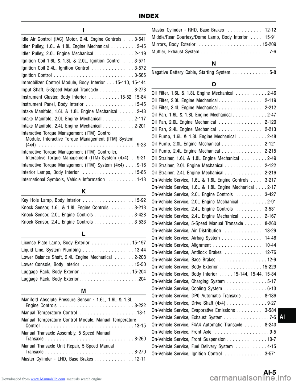
Downloaded from www.Manualslib.com manuals search engine I
Idle Air Control (IAC) Motor, 2.4L Engine Controls....3-541
Idler Pulley, 1.6L & 1.8L Engine Mechanical .........2-45
Idler Pulley, 2.0L Engine Mechanical ..............2-119
Ignition Coil 1.6L & 1.8L & 2.0L, Ignition Control ....3-571
Ignition Coil 2.4L, Ignition Control ...............3-572
Ignition Control ............................ 3-565
Immobilizer Control Module, Body Interior . . . 15-110, 15-144
Input Shaft, 5-Speed Manual Transaxle ............8-278
Instrument Cluster, Body Interior ...........15-52, 15-84
Instrument Panel, Body Interior .................15-45
Intake Manifold, 1.6L & 1.8L Engine Mechanical ......2-43
Intake Manifold, 2.0L Engine Mechanical ...........2-117
Intake Manifold, 2.4L Engine Mechanical ...........2-201
Interactive Torque Management (ITM) Control Module, Interactive Torque Management (ITM) System
(4x4) .................................. 9-23
Interactive Torque Management (ITM) Controller, Interactive Torque Management (ITM) System (4x4) . . 9-21
Interactive Torque Management (ITM) System (4x4) ....9-16
Interior Lamps, Body Interior ..................15-85
International Symbols, Vehicle Information ..........1-13
K
Key Hole Lamp, Body Interior ..................15-92
Knock Sensor, 1.6L & 1.8L Engine Controls ........3-218
Knock Sensor, 2.0L Engine Controls ..............3-428
Knock Sensor, 2.4L Engine Controls ..............3-533
L
License Plate Lamp, Body Exterior ..............15-197
Liquid Line, System Plumbing ..................13-44
Lower Balance Shaft, 2.4L Engine Mechanical .......2-208
Lower Console, Body Interior ..................15-50
Luggage Rack, Body Exterior ..................15-204
Luggage Rack, Body Exterior .....................204
M
Manifold Absolute Pressure Sensor - 1.6L, 1.6L & 1.8L
Engine Controls .......................... 3-222
Manual Temperature Control ....................13-1
Manual Temperature Control Module, Manual Temperature Control ................................ 13-15
Manual Transaxle Assembly, 5-Speed Manual Transaxle ............................... 8-260
Manual Transaxle Unit Repair, 5-Speed Manual Transaxle ............................... 8-270
Master Cylinder - LHD, Base Brakes ..............12-11Master Cylinder - RHD, Base Brakes
.............12-12
Middle/Rear Courtesy/Dome Lamp, Body Interior .....15-91
Mirrors, Body Exterior ...................... 15-209
Muffler, Exhaust System ........................7-6
N
Negative Battery Cable, Starting System .............5-8
O
Oil Filter, 1.6L & 1.8L Engine Mechanical ...........2-46
Oil Filter, 2.0L Engine Mechanical ................2-119
Oil Filter, 2.4L Engine Mechanical ................2-212
Oil Pan, 1.6L & 1.8L Engine Mechanical ............2-47
Oil Pan, 2.0L Engine Mechanical ................2-120
Oil Pan, 2.4L Engine Mechanical ................2-213
Oil Pump, 1.6L & 1.8L Engine Mechanical ..........2-48
Oil Pump, 2.0L Engine Mechanical ...............2-121
Oil Pump, 2.4L Engine Mechanical ...............2-215
Oil Strainer, 1.6L & 1.8L Engine Mechanical .........2-49
Oil Strainer, 2.0L Engine Mechanical ..............2-122
Oil Strainer, 2.4L Engine Mechanical ..............2-216
On-Vehicle Service, 1.6L & 1.8L Engine Controls .....3-217
On-Vehicle Service, 1.6L & 1.8L Engine Mechanical ....2-17
On-Vehicle Service, 2.0L Engine Controls ..........3-427
On-Vehicle Service, 2.0L Engine Mechanical .........2-91
On-Vehicle Service, 2.4L Engine Controls ..........3-531
On-Vehicle Service, 2.4L Engine Mechanical ........2-167
On-Vehicle Service, 5-Speed Manual Transaxle .......8-260
On-Vehicle Service, Air Distribution ..............13-29
On-Vehicle Service, Airbag System ...............14-46
On-Vehicle Service, Alignment ..................10-44
On-Vehicle Service, Antilock Brakes ..............12-76
On-Vehicle Service, Base Brakes .................12-9
On-Vehicle Service, Body Exterior ...............15-229
On-Vehicle Service, Body Interior .....15-144, 15-44, 15-84
On-Vehicle Service, Charging System ..............5-17
On-Vehicle Service, Cooling System ...............6-13
On-Vehicle Service, DP0 Automatic Transaxle ........8-136
On-Vehicle Service, Drive Shaft (4x4) ..............9-27
On-Vehicle Service, Evaporative Emissions ..........3-584
On-Vehicle Service, Exhaust System ................7-5
On-Vehicle Service, F4A4 Automatic Transaxle .......8-240
On-Vehicle Service, Front Axle ...................9-5
On-Vehicle Service, Front Suspension ..............10-7
On-Vehicle Service, Fuel Delivery System ...........4-15
On-Vehicle Service, Ignition
Control .............. 3-571
INDEX
AI
AI-5