2009 CHERY TIGGO oil pressure
[x] Cancel search: oil pressurePage 897 of 1903

Downloaded from www.Manualslib.com manuals search engine 3. Disconnect the fuel return pipe (2).
4. Remove the fuel pressure regulator mounting bolts(1).
(Tighten: Fuel pressure regulator mounting bolts to
9 N·m)
5. Remove the fuel pressure regulator.
6. Installation is in the reverse order of removal.
Installation Notes:
• Install new seals on the fuel pressure regulator sealing surfaces.
• Coat the surface of the fuel pressure regulator O-ring seal with clean engine oil before assembly.
• While installing the fuel pressure regulator, ensure that the fuel pressure regulator rotates smoothly in the fuel
distribution tube. If it does not rotate smoothly, the O-ring seal may have been damaged. Remove the fuel
pressure regulator and inspect the O-ring seal for damage.
Fuel Pressure Regulator Inspection
1. Connect a fuel pressure gauge to the inlet fuel pipe.
2. Start and idle the engine (note the fuel pressure).
3. Increase the engine speed to 2500 RPM (note the fuel pressure).
SPECIFICATION PRESSURE
Idle 350 kPa
2500 RPM 350 kPa
ON-VEHICLE SERVICE
LTSM040006
04–24Chery Automobile Co., Ltd.
Page 926 of 1903

Downloaded from www.Manualslib.com manuals search engine DIAGNOSIS AND TESTING
Cooling System Pressure Test
WARNING!
Always allow the engine to cool before opening the cooling system. Do not remove the coolant pressure relief
cap when the engine is operating or the cooling system is hot. The cooling system is under pressure; steam and
hot liquid can come out forcefully when the cap is loosened slightly. Failure to follow these instructions may
result in serious personal injury.
CAUTION:
Do not pressurize the cooling system beyond the maximum pressure listed in the specifications
table in this section, or cooling system components can be damaged.
1. Turn the engine off.
2. Check the engine coolant level. Adjust the coolant level as necessary.
3. Attach the pressure tester to the coolant recovery reservoir. Install a pressure test pump to the quick-connectfitting of the test adapter.
4. Pressurize the engine cooling system to 111 kPa. Observe the gauge reading for approximately 2 minutes. Pres- sure should not drop during this time. If the pressure drops within this time, inspect for leaks and repair as nec-
essary.
5. If no leaks are found and the pressure drops, the pressure relief cap may be leaking. Install a new pressure relief cap and retest the system.
6. If no leaks are found after a new pressure relief cap is installed, and the pressure drops, the leak may be inter- nal to the radiator transmission cooler (if equipped). Inspect the coolant for transmission fluid and the transmis-
sion fluid for coolant. Repair as necessary.
7. If there is no contamination of the coolant or transmission fluid, the leak may be internal to the engine. Inspect the coolant for engine oil and the engine oil for coolant.
8. Release the system pressure by loosening the pressure relief cap. Check the coolant level and adjust as nec- essary.
Cooling System Concentration Test
CAUTION:
Do not mix types of coolant, corrosion protection will be severely reduced.
Coolant concentration should be checked when any additional coolant is added to the cooling system or after a cool-
ant drain, flush and refill. The coolant mixture offers optimum engine cooling and protection against corrosion when
mixed to a freeze point of -37°C to -46°C. The use of a hydrometer or a refractometer can be used to test coolant
concentration.
06
06–11Chery Automobile Co., Ltd.
Page 1305 of 1903
Downloaded from www.Manualslib.com manuals search engine WARNING!
Do not remove the strut rod nut while the strut assembly is installed in the vehicle, or before the coil spring is
compressed with a spring compressor. The spring is held under high pressure and must be compressed before
the strut rod nut can be removed.
CAUTION:
At no time when servicing a vehicle can a sheet metal screw, bolt, or other metal fastener be
installed in the shock tower to replace the original plastic clamp. It may come in contact with the
strut or coil spring.
CAUTION:
The wheel bearing will be damaged if the vehicle is rolled with the axle shaft hub nut loose.
Operation
The front suspension utilizes a MacPherson strut system. This suspension system incorporates a strut assembly that
takes the place of the upper arm and ball joint. The strut performs the function of a shock absorber and is encom-
passed by a coil spring.
Specifications
Torque Specifications
DESCRIPTIONTORQUE (N·m)
Connecting Rod And Front Stabilizer Bar 40 - 50
Connect The Right And Left Assembly Of Front Drive
Shaft With Brake Disc 260 - 270
Control Arm And Sub-Frame 170 - 190
Connect Intermediate Propeller Shaft With Vehicle Body 58 - 68
Connecting Rod With Lower Suspension Lever 40 - 50
Connect Control Arm Knuckle Pin With Knuckle
Assembly 110 - 130
Connect Control Arm Knuckle Pin With Control Arm 140 - 160
Front Connecting Rod And Front Shock Absorber 40 - 50
Front Axle Shaft Nut 135
Fix Stabilizer Bar Clamp To Sub-Frame 22 - 28
Front Shock Absorber and Coil Spring 100 - 120
Front Suspension Strut And Vehicle Body 45 - 55
Front Suspension And Bracket 75 - 85
Insert From The Lower Part Of Sub-Frame, And The
Bolt Is On The Suspension. The Middle Part Shall Be
Clamped To The Main Longitudinal Beam Of Engine 110 - 130
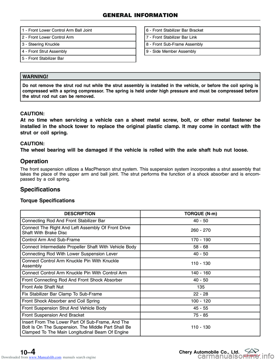
1 - Front Lower Control Arm Ball Joint
2 - Front Lower Control Arm
3 - Steering Knuckle
4 - Front Strut Assembly
5 - Front Stabilizer Bar6 - Front Stabilizer Bar Bracket
7 - Front Stabilizer Bar Link
8 - Front Sub-Frame Assembly
9 - Side Member Assembly
GENERAL INFORMATION
LTSM100008
10–4Chery Automobile Co., Ltd.
Page 1315 of 1903
Downloaded from www.Manualslib.com manuals search engine Operation
The strut assembly cushions the ride of the vehicle, controlling vibration, jounce and rebound of the suspension. The
coil spring controls ride quality and maintains proper ride height. The spring isolators isolate the coil spring at the top
and bottom from coming into metal-to-metal contact with the upper mounting seat and the strut. The strut dampens
jounce and rebound motions of the coil spring and suspension.
Diagnosis & Testing
Before removing the front strut, perform the following to test the front strut functionality:
•Adjust the tire pressure to all tires to proper specifications.
• Push and shake the front of the vehicle three or four times with identical force every time
• During the pushing and recoiling, the resistance and recoil times of the vehicle should be equal.
• If the strut (shock absorber) functions properly, the vehicle will recoil several times and then stop recoiling after
the pushing force is removed.
Removal & Installation
1. Raise and support the vehicle.
2. Remove the wheel mounting nuts and the wheel assembly.
(Tighten: Wheel mounting nuts to 110 N·m)
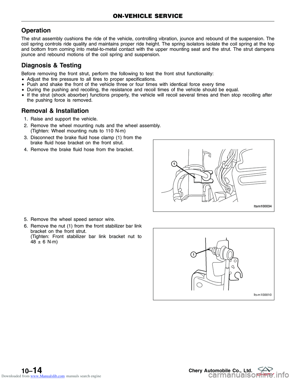
3. Disconnect the brake fluid hose clamp (1) from the brake fluid hose bracket on the front strut.
4. Remove the brake fluid hose from the bracket.
5. Remove the wheel speed sensor wire.
6. Remove the nut (1) from the front stabilizer bar link bracket on the front strut.
(Tighten: Front stabilizer bar link bracket nut to
48 ± 6 N·m)
ON-VEHICLE SERVICE
LTSM100034
LTSM100010
10–14Chery Automobile Co., Ltd.
Page 1317 of 1903
Downloaded from www.Manualslib.com manuals search engine Front Coil Spring
Description
A coil-over front strut assembly supports each front coil spring. The top of the strut assembly mounts to the strut
tower.
Operation
Coil springs are designed to store energy and subsequently release it and to absorb shock and maintain a force
between contacting surfaces. Coil springs are rated for specific vehicle applications.
NOTE :
Each component is serviced by removing the strut assembly from the vehicle and disassembling it. Coil springs are
rated separately for each corner or side of the vehicle depending on optional equipment and type of vehicle service.
If a coil spring requires replacement, be sure that it is replaced with a spring meeting the correct load rating for the
vehicle and its specific options.
Removal & Installation
CAUTION:
At no time when servicing a vehicle can a sheet metal screw, bolt or other metal fastener be
installed into the strut tower to take the place of an original plastic clamp. Also, do not drill holes
into the front strut tower for the installation of any metal fasteners into the strut tower area indi-
cated.
1. Raise and support the vehicle.
2. Remove the front strut assembly (See Front Strut Removal & Installation in Section 10 Suspension).
WARNING!
Do not remove the strut rod nut before the coil spring is properly compressed. The coil spring is held under
pressure. The coil spring must be compressed, removing spring tension from the upper mount and bearing,
before the strut rod nut is removed.
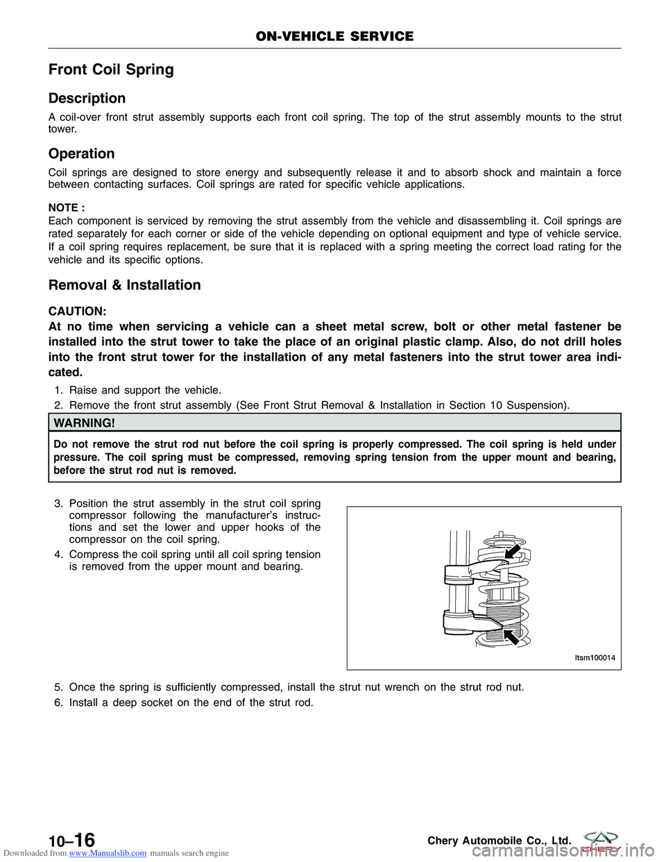
3. Position the strut assembly in the strut coil springcompressor following the manufacturer’s instruc-
tions and set the lower and upper hooks of the
compressor on the coil spring.
4. Compress the coil spring until all coil spring tension is removed from the upper mount and bearing.
5. Once the spring is sufficiently compressed, install the strut nut wrench on the strut rod nut.
6. Install a deep socket on the end of the strut rod.
ON-VEHICLE SERVICE
LTSM100014
10–16Chery Automobile Co., Ltd.
Page 1322 of 1903
Downloaded from www.Manualslib.com manuals search engine UNIT REPAIR
Front Strut
Disassemble
NOTE :
The strut assembly must be removed from the vehicle for it to be disassembled and assembled. For the disassembly
and assembly of the strut assembly, use a strut spring compressor, or the equivalent, to compress the coil spring.
Follow the manufacturer’s instructions closely.1. Remove the front strut assembly (See Front Strut Removal & Installation in Section 10 Suspension).
2. If both struts are being serviced at the same time, mark both the coil springs and strut assemblies according to which side of the vehicle the strut is being removed from.
WARNING!
Do not remove the strut rod nut before the coil spring is properly compressed. The coil spring is held under
pressure. The coil spring must be compressed, removing spring tension from the upper mount and bearing,
before the strut rod nut is removed.
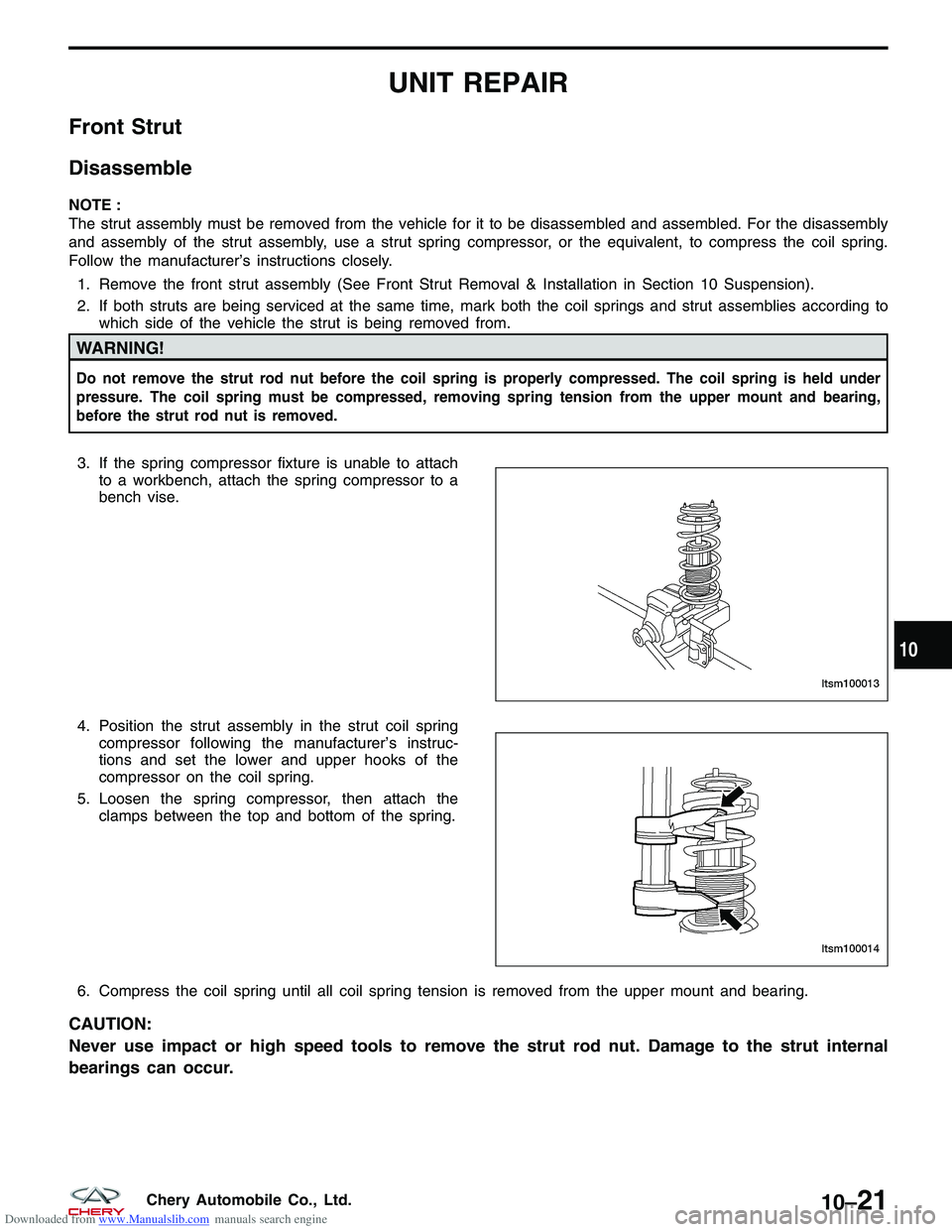
3. If the spring compressor fixture is unable to attachto a workbench, attach the spring compressor to a
bench vise.
4. Position the strut assembly in the strut coil spring compressor following the manufacturer’s instruc-
tions and set the lower and upper hooks of the
compressor on the coil spring.
5. Loosen the spring compressor, then attach the clamps between the top and bottom of the spring.
6. Compress the coil spring until all coil spring tension is removed from the upper mount and bearing.
CAUTION:
Never use impact or high speed tools to remove the strut rod nut. Damage to the strut internal
bearings can occur.
LTSM100013
LTSM100014
10
10–21Chery Automobile Co., Ltd.
Page 1340 of 1903
Downloaded from www.Manualslib.com manuals search engine GENERAL INFORMATION
Description
Vehicle wheel alignment is the positioning of all interrelated front and rear suspension angles. These angles affect the
handling and steering of the vehicle when it is in motion. Proper wheel alignment is essential for efficient steering,
good directional stability, and proper tire wear.
The method of checking a vehicle’s front and rear wheel alignment varies depending on the manufacturer and type
of equipment used. The manufacturer’s instructions should always be followed to ensure accuracy of the alignment.
On this vehicle, the suspension angles that can be adjusted are as follows:
Front Axle
•Camber
• Caster
• Toe-in
Rear Axle
• Camber
• Toe-in
Check the wheel alignment and make all wheel alignment adjustments with the vehicle standing at its proper curb
height specification. Curb height is the normal riding height of the vehicle. It is measured from a certain point on the
vehicle to the ground or a designated area while the vehicle is sitting on a flat, level surface.
Operation
Curb Height Measurement
The wheel alignment is to be checked and all alignment adjustments made with the vehicle at its required curb height
specification.
• Vehicle height is to be checked with the vehicle on a flat, level surface, preferably a vehicle alignment rack.
• The tires are to be inflated to the recommended pressure.
• All tires are to be the same size as standard equipment.
• Vehicle height is checked with the fuel tank full of fuel, and no passenger or luggage compartment load.
• Vehicle height is not adjustable.
• If the measurement is not within specifications, inspect the vehicle for bent or weak suspension components.
• Compare the parts tag on the suspect coil spring(s) to the parts book and the vehicle sales code, checking for
a match.
• Once removed from the vehicle, compare the coil spring height to a new or known good coil spring. The
heights should vary if the suspect spring is weak.
NOTE :
Prior to reading the curb height measurement, the front and rear of the vehicle must be jounced to settle the sus-
pension. Induce jounce by pushing down on the center of the bumper (fascia), using care not to damage the vehicle,
moving the vehicle up and down, gradually increasing the suspension travel with each stroke. Release the bumper at
the bottom of each stroke, repeating this action several times. Perform this to both front and rear suspensions an
equal number of times.
Pre-Wheel Alignment Inspection
Before any attempt is made to change or correct the wheel alignment, the following inspection and necessary cor-
rections must be made to the vehicle to ensure proper alignment. 1. Verify the fuel tank is full of fuel. If the fuel tank is not full, the reduction in weight will affect the curb height of the vehicle and the alignment specifications.
2. The passenger and luggage compartments of the vehicle should be free of any load that is not factory equip- ment.
10
10–39Chery Automobile Co., Ltd.
Page 1398 of 1903
Downloaded from www.Manualslib.com manuals search engine Rear Disc Brake
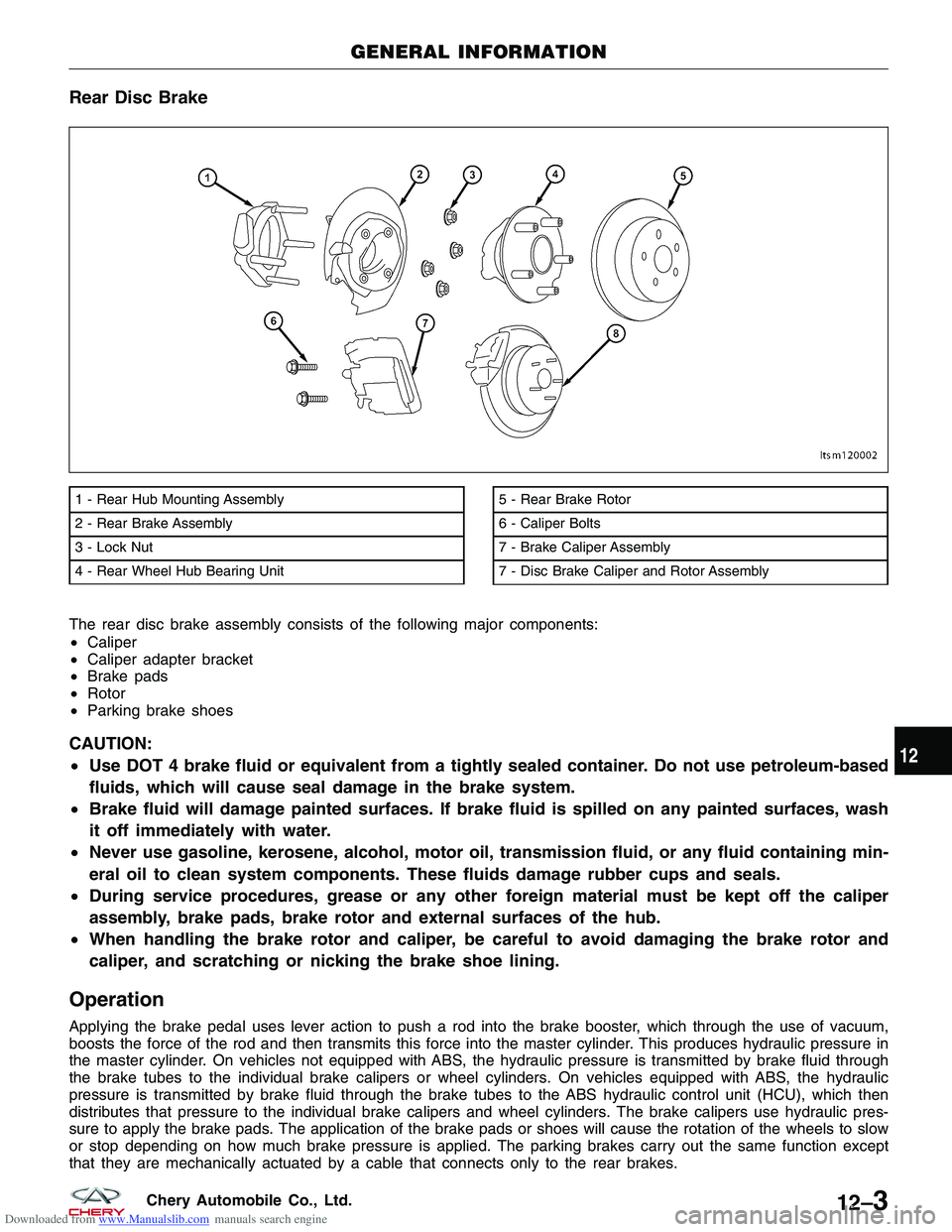
The rear disc brake assembly consists of the following major components:
•Caliper
• Caliper adapter bracket
• Brake pads
• Rotor
• Parking brake shoes
CAUTION:
•Use DOT 4 brake fluid or equivalent from a tightly sealed container. Do not use petroleum-based
fluids, which will cause seal damage in the brake system.
• Brake fluid will damage painted surfaces. If brake fluid is spilled on any painted surfaces, wash
it off immediately with water.
• Never use gasoline, kerosene, alcohol, motor oil, transmission fluid, or any fluid containing min-
eral oil to clean system components. These fluids damage rubber cups and seals.
• During service procedures, grease or any other foreign material must be kept off the caliper
assembly, brake pads, brake rotor and external surfaces of the hub.
• When handling the brake rotor and caliper, be careful to avoid damaging the brake rotor and
caliper, and scratching or nicking the brake shoe lining.
Operation
Applying the brake pedal uses lever action to push a rod into the brake booster, which through the use of vacuum,
boosts the force of the rod and then transmits this force into the master cylinder. This produces hydraulic pressure in
the master cylinder. On vehicles not equipped with ABS, the hydraulic pressure is transmitted by brake fluid through
the brake tubes to the individual brake calipers or wheel cylinders. On vehicles equipped with ABS, the hydraulic
pressure is transmitted by brake fluid through the brake tubes to the ABS hydraulic control unit (HCU), which then
distributes that pressure to the individual brake calipers and wheel cylinders. The brake calipers use hydraulic pres-
sure to apply the brake pads. The application of the brake pads or shoes will cause the rotation of the wheels to slow
or stop depending on how much brake pressure is applied. The parking brakes carry out the same function except
that they are mechanically actuated by a cable that connects only to the rear brakes.
1 - Rear Hub Mounting Assembly
2 - Rear Brake Assembly
3 - Lock Nut
4 - Rear Wheel Hub Bearing Unit5 - Rear Brake Rotor
6 - Caliper Bolts
7 - Brake Caliper Assembly
7 - Disc Brake Caliper and Rotor Assembly
GENERAL INFORMATION
LTSM120002
12
12–3Chery Automobile Co., Ltd.