2009 CHERY TIGGO oil pressure
[x] Cancel search: oil pressurePage 1494 of 1903
Downloaded from www.Manualslib.com manuals search engine DIAGNOSIS & TESTING
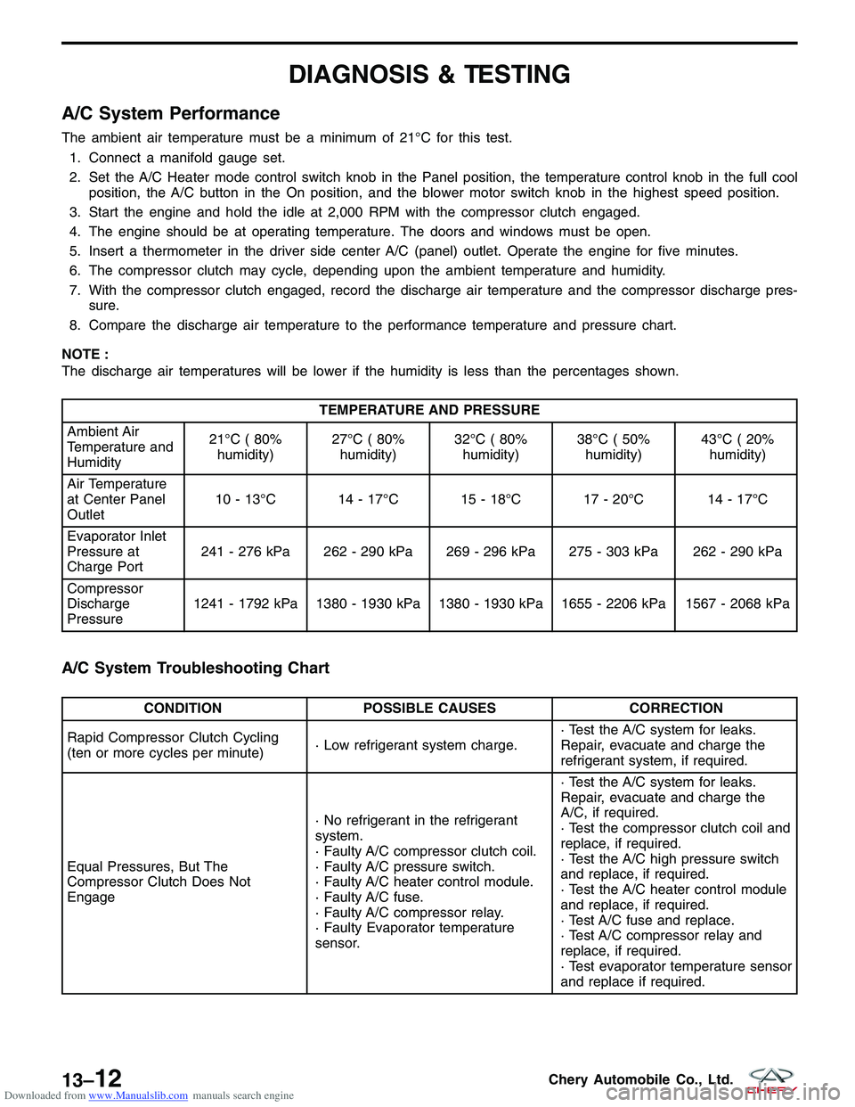
A/C System Performance
The ambient air temperature must be a minimum of 21°C for this test.1. Connect a manifold gauge set.
2. Set the A/C Heater mode control switch knob in the Panel position, the temperature control knob in the full cool position, the A/C button in the On position, and the blower motor switch knob in the highest speed position.
3. Start the engine and hold the idle at 2,000 RPM with the compressor clutch engaged.
4. The engine should be at operating temperature. The doors and windows must be open.
5. Insert a thermometer in the driver side center A/C (panel) outlet. Operate the engine for five minutes.
6. The compressor clutch may cycle, depending upon the ambient temperature and humidity.
7. With the compressor clutch engaged, record the discharge air temperature and the compressor discharge pres- sure.
8. Compare the discharge air temperature to the performance temperature and pressure chart.
NOTE :
The discharge air temperatures will be lower if the humidity is less than the percentages shown.
TEMPERATURE AND PRESSURE
Ambient Air
Temperature and
Humidity 21°C ( 80%
humidity) 27°C ( 80%
humidity) 32°C ( 80%
humidity) 38°C ( 50%
humidity) 43°C ( 20%
humidity)
Air Temperature
at Center Panel
Outlet 10 - 13°C 14 - 17°C 15 - 18°C 17 - 20°C 14 - 17°C
Evaporator Inlet
Pressure at
Charge Port 241 - 276 kPa 262 - 290 kPa 269 - 296 kPa 275 - 303 kPa 262 - 290 kPa
Compressor
Discharge
Pressure 1241 - 1792 kPa 1380 - 1930 kPa 1380 - 1930 kPa 1655 - 2206 kPa 1567 - 2068 kPa
A/C System Troubleshooting Chart
CONDITION
POSSIBLE CAUSES CORRECTION
Rapid Compressor Clutch Cycling
(ten or more cycles per minute) · Low refrigerant system charge.· Test the A/C system for leaks.
Repair, evacuate and charge the
refrigerant system, if required.
Equal Pressures, But The
Compressor Clutch Does Not
Engage · No refrigerant in the refrigerant
system.
· Faulty A/C compressor clutch coil.
· Faulty A/C pressure switch.
· Faulty A/C heater control module.
· Faulty A/C fuse.
· Faulty A/C compressor relay.
· Faulty Evaporator temperature
sensor.· Test the A/C system for leaks.
Repair, evacuate and charge the
A/C, if required.
· Test the compressor clutch coil and
replace, if required.
· Test the A/C high pressure switch
and replace, if required.
· Test the A/C heater control module
and replace, if required.
· Test A/C fuse and replace.
· Test A/C compressor relay and
replace, if required.
· Test evaporator temperature sensor
and replace if required.
13–12Chery Automobile Co., Ltd.
Page 1495 of 1903
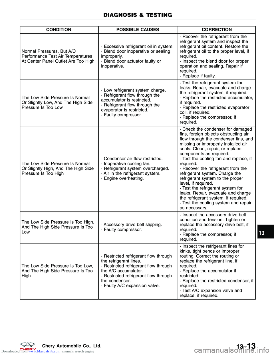
Downloaded from www.Manualslib.com manuals search engine CONDITIONPOSSIBLE CAUSES CORRECTION
Normal Pressures, But A/C
Performance Test Air Temperatures
At Center Panel Outlet Are Too High · Excessive refrigerant oil in system.
· Blend door inoperative or sealing
improperly.
· Blend door actuator faulty or
inoperative.· Recover the refrigerant from the
refrigerant system and inspect the
refrigerant oil content. Restore the
refrigerant oil to the proper level, if
required.
· Inspect the blend door for proper
operation and sealing. Repair if
required.
· Replace if faulty.
The Low Side Pressure Is Normal
Or Slightly Low, And The High Side
Pressure Is Too Low · Low refrigerant system charge.
· Refrigerant flow through the
accumulator is restricted.
· Refrigerant flow through the
evaporator is restricted.
· Faulty compressor.· Test the refrigerant system for
leaks. Repair, evacuate and charge
the refrigerant system, if required.
· Replace the restricted accumulator,
if required.
· Replace the restricted evaporator
coil, if required.
· Replace the compressor, if
required.
The Low Side Pressure Is Normal
Or Slightly High, And The High Side
Pressure Is Too High · Condenser air flow restricted.
· Inoperative cooling fan.
· Refrigerant system overcharged.
· Air in the refrigerant system.
· Engine overheating.· Check the condenser for damaged
fins, foreign objects obstructing air
flow through the condenser fins, and
missing or improperly installed air
seals. Clean, repair, or replace
components as required.
· Test the cooling fan and replace, if
required.
· Recover the refrigerant from the
refrigerant system. Charge the
refrigerant system to the proper
level, if required.
· Test the refrigerant system for
leaks. Repair, evacuate and charge
the refrigerant system, if required.
· Test the cooling system and repair
as necessary.
The Low Side Pressure Is Too High,
And The High Side Pressure Is Too
Low · Accessory drive belt slipping.
· Faulty compressor.· Inspect the accessory drive belt
condition and tension. Tighten or
replace the accessory drive belt, if
required.
· Replace the compressor, if
required.
The Low Side Pressure Is Too Low,
And The High Side Pressure Is Too
High · Restricted refrigerant flow through
the refrigerant lines.
· Restricted refrigerant flow through
the A/C accumulator.
· Restricted refrigerant flow through
the condenser.
· Faulty A/C expansion valve.· Inspect the refrigerant lines for
kinks, tight bends or improper
routing. Correct the routing or
replace the refrigerant line, if
required.
· Replace the accumulator if
restricted.
· Replace the restricted condenser, if
required.
· Test A/C expansion valve and
replace, if required.
DIAGNOSIS & TESTING
13
13–13Chery Automobile Co., Ltd.
Page 1515 of 1903
Downloaded from www.Manualslib.com manuals search engine GENERAL INFORMATION
Description
The A/C refrigerant lines and pipes are used to carry the refrigerant between the various A/C system components.
Any kinks or sharp bends in the refrigerant lines and hoses will reduce the capacity of the entire A/C system and can
reduce the flow of refrigerant within the system.
Operation
High pressure is produced in a refrigerant system when the A/C compressor is operating. Extreme care must be
exercised to make sure that each of the refrigerant system connections is pressure-tight and leak free. It is a good
practice to inspect all flexible hose refrigerant lines at least once a year to make sure they are in good condition and
properly routed. Depending on vehicle, model and market application, refrigerant lines are connected to each other or
other A/C system components with block-type or quick-connect type fittings. To ensure the integrity of the refrigerant
system, O-rings and/or gaskets may be used to seal the refrigerant system connections. The refrigerant lines and
hoses cannot be repaired and must be replaced if leaking or damaged.
WARNING!
The A/C system contains refrigerant under high pressure. Repairs should only be performed by qualified service
personnel. Serious or fatal injury may result from improper service procedures.
If accidental A/C system discharge occurs, ventilate the work area before resuming service. Large amounts of
refrigerant released in a closed work area will displace the oxygen and cause suffocation and serious or fatal
injury.
CAUTION:
Never add R-12 to a refrigerant system designed to use R-134a. Do not use R-12 equipment or
parts on an R-134a A/C system. These refrigerants are not compatible and damage to the A/C sys-
tem will result.
CAUTION:
Never use R-12 refrigerant oil in an A/C system designed to use R-134a refrigerant oil. These refrig-
erant oils are not compatible and damage to the A/C system will result.
CAUTION:
Do not run the engine with a vacuum pump in operation or with a vacuum present within the A/C
system. Failure to follow this caution will result in serious A/C compressor damage.
CAUTION:
Do not overcharge the refrigerant system. Overcharging will cause excessive compressor head
pressure and can cause compressor noise and A/C system failure.
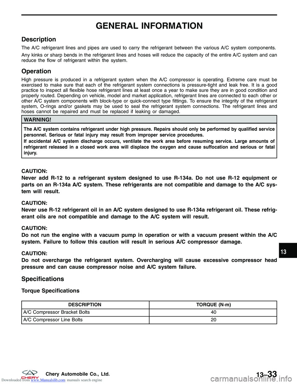
Specifications
Torque Specifications
DESCRIPTIONTORQUE (N·m)
A/C Compressor Bracket Bolts 40
A/C Compressor Line Bolts 20
13
13–33Chery Automobile Co., Ltd.
Page 1518 of 1903
Downloaded from www.Manualslib.com manuals search engine 12. If the noise is from liquid refrigerant slugging in the A/C suction line, replace the A/C accumulator and check therefrigerant oil level and the refrigerant system charge.
13. If a slugging condition still exists after replacing the A/C accumulator, replace the A/C compressor.
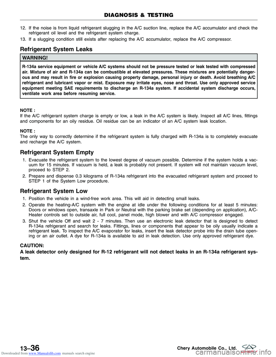
Refrigerant System Leaks
WARNING!
R-134a service equipment or vehicle A/C systems should not be pressure tested or leak tested with compressed
air. Mixture of air and R-134a can be combustible at elevated pressures. These mixtures are potentially danger-
ous and may result in fire or explosion causing property damage, personal injury or death. Avoid breathing A/C
refrigerant and lubricant vapor or mist. Exposure may irritate eyes, nose and throat. Use only approved service
equipment meeting SAE requirements to discharge an R-134a system. If accidental system discharge occurs,
ventilate work area before resuming service.
NOTE :
If the A/C refrigerant system charge is empty or low, a leak in the A/C system is likely. Inspect all A/C lines, fittings
and components for an oily residue. Oil residue can be an indicator of an A/C system leak location.
NOTE :
The only way to correctly determine if the refrigerant system is fully charged with R-134a is to completely evacuate
and recharge the A/C system.
Refrigerant System Empty
1. Evacuate the refrigerant system to the lowest degree of vacuum possible. Determine if the system holds a vac- uum for 15 minutes. If vacuum is held, a leak is probably not present. If system will not maintain vacuum level,
proceed to STEP 2.
2. Prepare and dispense 0.3 kilograms of R-134a refrigerant into the evacuated refrigerant system and proceed to STEP 1 of the System Low procedure.
Refrigerant System Low
1. Position the vehicle in a wind-free work area. This will aid in detecting small leaks.
2. Operate the heating-A/C system with the engine at idle under the following conditions for at least 5 minutes:Doors or windows open, transaxle in Park or Neutral with the parking brake set (depending on application), A/C-
Heater controls set to outside air, full cool, panel mode, high blower and with A/C compressor engaged.
3. Shut the vehicle Off and wait2-7minutes. Then use an electronic leak detector that is designed to detect R-134a refrigerant and search for leaks. Fittings, lines or components that appear to be oily usually indicate a
refrigerant leak. To inspect the A/C evaporator for leaks, insert the leak detector probe into the drain tube open-
ing or an air outlet. A dye for R-134a is available to aid in leak detection. Use only approved refrigerant dye.
CAUTION:
A leak detector only designed for R-12 refrigerant will not detect leaks in an R-134a refrigerant sys-
tem.
DIAGNOSIS & TESTING
13–36Chery Automobile Co., Ltd.
Page 1520 of 1903
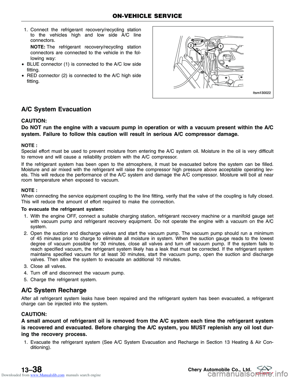
Downloaded from www.Manualslib.com manuals search engine 1. Connect the refrigerant recovery/recycling stationto the vehicles high and low side A/C line
connectors.
NOTE: The refrigerant recovery/recycling station
connectors are connected to the vehicle in the fol-
lowing way:
• BLUE connector (1) is connected to the A/C low side
fitting.
• RED connector (2) is connected to the A/C high side
fitting.
A/C System Evacuation
CAUTION:
Do NOT run the engine with a vacuum pump in operation or with a vacuum present within the A/C
system. Failure to follow this caution will result in serious A/C compressor damage.
NOTE :
Special effort must be used to prevent moisture from entering the A/C system oil. Moisture in the oil is very difficult
to remove and will cause a reliability problem with the A/C compressor.
If the refrigerant system has been open to the atmosphere, it must be evacuated before the system can be filled.
Moisture and air mixed with the refrigerant will raise the compressor high pressure above acceptable operating lev-
els. This will reduce the performance of the A/C system and damage the A/C compressor. Moisture will boil at near
room temperature when exposed to vacuum.
NOTE :
When connecting the service equipment coupling to the line fitting, verify that the valve of the coupling is fully closed.
This will reduce the amount of effort required to make the connection.
To evacuate the refrigerant system:
1. With the engine OFF, connect a suitable charging station, refrigerant recovery machine or a manifold gauge set with vacuum pump and refrigerant recovery equipment. Do not operate the engine with a vacuum on the A/C
system.
2. Open the suction and discharge valves and start the vacuum pump. The vacuum pump should run a minimum of 45 minutes prior to charge to eliminate all moisture in system. When the suction gauge reads to the lowest
degree of vacuum possible for 30 minutes, close all valves and turn off vacuum pump. If the system fails to
reach specified vacuum, the refrigerant system likely has a leak that must be corrected. If the refrigerant system
maintains specified vacuum for at least 30 minutes, start the vacuum pump, open the suction and discharge
valves. Then allow the system to evacuate an additional 10 minutes.
3. Close all valves.
4. Turn off and disconnect the vacuum pump.
5. Charge the refrigerant system.
A/C System Recharge
After all refrigerant system leaks have been repaired and the refrigerant system has been evacuated, a refrigerant
charge can be injected into the system.
CAUTION:
A small amount of refrigerant oil is removed from the A/C system each time the refrigerant system
is recovered and evacuated. Before charging the A/C system, you MUST replenish any oil lost dur-
ing the recovery process.
1. Evacuate the refrigerant system (See A/C System Evacuation and Recharge in Section 13 Heating & Air Con- ditioning).
ON-VEHICLE SERVICE
LTSM130022
13–38Chery Automobile Co., Ltd.
Page 1523 of 1903
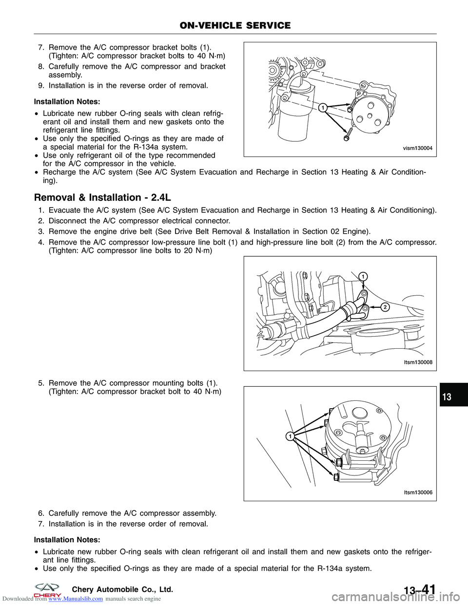
Downloaded from www.Manualslib.com manuals search engine 7. Remove the A/C compressor bracket bolts (1).(Tighten: A/C compressor bracket bolts to 40 N·m)
8. Carefully remove the A/C compressor and bracket assembly.
9. Installation is in the reverse order of removal.
Installation Notes:
• Lubricate new rubber O-ring seals with clean refrig-
erant oil and install them and new gaskets onto the
refrigerant line fittings.
• Use only the specified O-rings as they are made of
a special material for the R-134a system.
• Use only refrigerant oil of the type recommended
for the A/C compressor in the vehicle.
• Recharge the A/C system (See A/C System Evacuation and Recharge in Section 13 Heating & Air Condition-
ing).
Removal & Installation - 2.4L
1. Evacuate the A/C system (See A/C System Evacuation and Recharge in Section 13 Heating & Air Conditioning).
2. Disconnect the A/C compressor electrical connector.
3. Remove the engine drive belt (See Drive Belt Removal & Installation in Section 02 Engine).
4. Remove the A/C compressor low-pressure line bolt (1) and high-pressure line bolt (2) from the A/C compressor.
(Tighten: A/C compressor line bolts to 20 N·m)
5. Remove the A/C compressor mounting bolts (1). (Tighten: A/C compressor bracket bolt to 40 N·m)
6. Carefully remove the A/C compressor assembly.
7. Installation is in the reverse order of removal.
Installation Notes:
• Lubricate new rubber O-ring seals with clean refrigerant oil and install them and new gaskets onto the refriger-
ant line fittings.
• Use only the specified O-rings as they are made of a special material for the R-134a system.
ON-VEHICLE SERVICE
VISM130004
LTSM130008
LTSM130006
13
13–41Chery Automobile Co., Ltd.
Page 1524 of 1903
Downloaded from www.Manualslib.com manuals search engine •Use only refrigerant oil of the type recommended for the A/C compressor in the vehicle.
• Recharge the A/C system (See A/C System Evacuation and Recharge in Section 13 Heating & Air Condition-
ing).
Evaporator
Description
The evaporator core is located in the HVAC housing, under the instrument panel. The evaporator coil is positioned in
the HVAC housing so that all air that enters the housing must pass over the fins of the evaporator before it is dis-
tributed through the system ducts and outlets. However, air passing over the evaporator core fins will only be con-
ditioned when the compressor is engaged and circulating refrigerant through the evaporator coil tubes.
Operation
Refrigerant enters the evaporator from the orifice tube as a low-temperature, low-pressure liquid. As air flows over
the fins of the evaporator, the humidity in the air condenses on the fins, and the heat from the air is absorbed by the
refrigerant. Heat absorption causes the refrigerant to boil and vaporize. The refrigerant becomes a low-pressure gas
before it leaves the evaporator. The evaporator core housing directs airflow from the blower motor through the evap-
orator core and heater core. All airflow from the blower motor passes through the evaporator core. The airflow is then
directed through or around the heater core by the temperature blend door(s).
Removal & Installation
1. Evacuate the A/C system (See A/C System Evacuation and Recharge in Section 13 Heating & Air Conditioning).
2. Remove the expansion valve.
3. Remove the HVAC housing (See HVAC Housing Removal and Installation in Section 13 Heating & Air Condi-
tioning).
4. Remove the retaining bolts and screws.
5. Remove the evaporator core.
6. Installation is in the reverse order of removal.
Installation Notes:
• Lubricate new rubber O-ring seals with clean refrigerant oil and install them and new gaskets onto the refriger-
ant line fittings.
• Use only the specified O-rings as they are made of a special material for the R-134a system.
• Use only refrigerant oil of the type recommended for the A/C compressor in the vehicle.
• Recharge the A/C system (See A/C System Evacuation and Recharge in Section 13 Heating & Air Condition-
ing).
Condenser
Description
The condenser is located in the air flow in front of the engine cooling radiator. The condenser transforms the refrig-
erant from a gas into a liquid. It is attached to the vehicle with bolts and the A/C lines with fittings.
Operation
When the heat is removed from the refrigerant, it condenses. When the refrigerant leaves the condenser, it becomes
a high-pressure liquid refrigerant. The volume of air flowing over the condenser fins is critical to the proper cooling
performance of the air conditioning system. Therefore, it is important that there are no objects placed in front of the
radiator grille openings in the front of the vehicle or foreign material on the condenser fins that might obstruct proper
air flow. Also, any factory-installed air seals or shrouds must be properly reinstalled following radiator or condenser
service.
ON-VEHICLE SERVICE
13–42Chery Automobile Co., Ltd.
Page 1526 of 1903
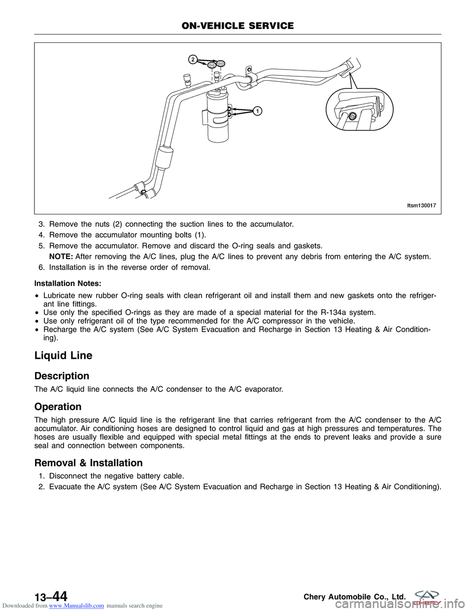
Downloaded from www.Manualslib.com manuals search engine 3. Remove the nuts (2) connecting the suction lines to the accumulator.
4. Remove the accumulator mounting bolts (1).
5. Remove the accumulator. Remove and discard the O-ring seals and gaskets.NOTE: After removing the A/C lines, plug the A/C lines to prevent any debris from entering the A/C system.
6. Installation is in the reverse order of removal.
Installation Notes:
• Lubricate new rubber O-ring seals with clean refrigerant oil and install them and new gaskets onto the refriger-
ant line fittings.
• Use only the specified O-rings as they are made of a special material for the R-134a system.
• Use only refrigerant oil of the type recommended for the A/C compressor in the vehicle.
• Recharge the A/C system (See A/C System Evacuation and Recharge in Section 13 Heating & Air Condition-
ing).
Liquid Line
Description
The A/C liquid line connects the A/C condenser to the A/C evaporator.
Operation
The high pressure A/C liquid line is the refrigerant line that carries refrigerant from the A/C condenser to the A/C
accumulator. Air conditioning hoses are designed to control liquid and gas at high pressures and temperatures. The
hoses are usually flexible and equipped with special metal fittings at the ends to prevent leaks and provide a sure
seal and connection between components.
Removal & Installation
1. Disconnect the negative battery cable.
2. Evacuate the A/C system (See A/C System Evacuation and Recharge in Section 13 Heating & Air Conditioning).
ON-VEHICLE SERVICE
LTSM130017
13–44Chery Automobile Co., Ltd.