Page 1649 of 1903
Downloaded from www.Manualslib.com manuals search engine Diagnostic Tools
•Diagnostic Scan Tool X-431
• Digital Multimeter
• Jumper Wire
Diagnostic Trouble Code (DTC) List
Instrument Cluster DTC List
DTC DTC DEFINITION
U0303 Fuel Sensor O/C or Shorted To Supply
U0303 Fuel Sensor Shorted To Ground
U040F Temperature Sensor O/C or Shorted To Supply
U040F Temperature Sensor Shorted To Ground
U029C Battery Over Voltage Error
U029C Battery Under Voltage Error
U050F EEPROM Checksum Error
DIAGNOSIS & TESTING
15
15–65Chery Automobile Co., Ltd.
Page 1653 of 1903
Downloaded from www.Manualslib.com manuals search engine Diagnostic Procedure
1.CHECK GROUND CONNECTION
• Turn ignition switch off.
• Loosen and retighten ground screws on the body (See Ground Inspection in Section 15 Body & Accessories).
• Inspect ground connection C-201 mounting position (See Vehicle Wiring Harness Information - Main Harness in
Section 16 Wiring).
Is the ground connection OK?
Ye s>>Go to the next step.
No
>>Repair or replace ground harness or connections.
2.CHECK INSTRUMENT CLUSTER (IC) ELECTRICAL CONNECTOR
• Disconnect Instrument Cluster (IC) electrical connector.
• Inspect the electrical connector for damage.
Is the electrical connector OK?
Ye s>>Go to the next step.
No
>>Repair or replace the electrical connector as necessary.
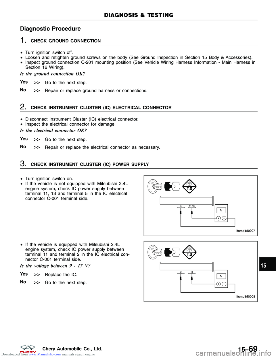
3.CHECK INSTRUMENT CLUSTER (IC) POWER SUPPLY
• Turn ignition switch on.
• If the vehicle is not equipped with Mitsubishi 2.4L
engine system, check IC power supply between
terminal 11, 13 and terminal 5 in the IC electrical
connector C-001 terminal side.
• If the vehicle is equipped with Mitsubishi 2.4L
engine system, check IC power supply between
terminal 11 and terminal 2 in the IC electrical con-
nector C-001 terminal side.
Is the voltage between9-17V?
Ye s>>Replace the IC.
No
>>Go to the next step.
DIAGNOSIS & TESTING
LTSMD150007
LTSMD150008
15
15–69Chery Automobile Co., Ltd.
Page 1654 of 1903
Downloaded from www.Manualslib.com manuals search engine 4.CHECK SYSTEM VOLTAGE
• Start the engine, raise the speed over 1000 RPM.
• Measure the charging voltage with the voltmeter at the battery positive and negative terminals.
Is the voltage less than 9 V?
Ye s>>Check the charging system.
No
>>Go to the next step.
5.CHECK THE BATTERY
• Start the engine, raise the speed over 1000 RPM for a few minutes.
• Turn ignition switch off.
• Measure the voltage drop with the voltmeter at the battery positive and negative terminals while cranking the
engine.
• Battery voltage should be more than approximate 9 V.
Is the check result normal?
Ye s>>Go to the next step.
No
>>Charge or replace the battery.
6.CHECK INSTRUMENT CLUSTER (IC) SUPPLY CIRCUIT
• Disconnect the battery negative cable.
• Disconnect the battery positive cable.
• Measure the resistance between IC terminal 11, 13 and battery positive cable.
• Continuity should exist.
Is the check result normal?
Ye s>>Go to the next step.
No
>>Check fuse.
Check the harness open or short to ground.
Check related components.
7.CHECK SYSTEM VOLTAGE
• Start the engine, raise the speed over 1000 RPM.
• Measure the charging voltage with the voltmeter at the battery positive and negative terminals.
Is the voltage more than 17 V?
Ye s>>Replace the AC generator.
No
>>Go to the next step.
DIAGNOSIS & TESTING
15–70Chery Automobile Co., Ltd.
Page 1655 of 1903
Downloaded from www.Manualslib.com manuals search engine 8.CHECK DTC
• With the X-431 scan tool, read IC DTCs.
• Refer to �DTC Confirmation Procedure�.
Is the DTC U029C still present?
Ye s>>Replace IC.
No
>>The system is now operating properly.
Reassemble the vehicle and verify the customers complaint is repaired.
DIAGNOSIS & TESTING
15
15–71Chery Automobile Co., Ltd.
Page 1658 of 1903
Downloaded from www.Manualslib.com manuals search engine Diagnostic Procedure
1.CHECK DTC
• Turn ignition switch on, with the scan tool, view and erase stored DTCs in the IC module.
• Turn ignition switch off, and wait a few seconds, then turn ignition switch on.
• With the scan tool, view active DTCs in the IC module.
Is DTC U040F present?
Ye s>>Go to the next step.
No
>>The conditions that caused this DTC to set are not present at this time (See Intermittent DTC Trouble-
shooting in Section 15 Body & Accessories for more information).
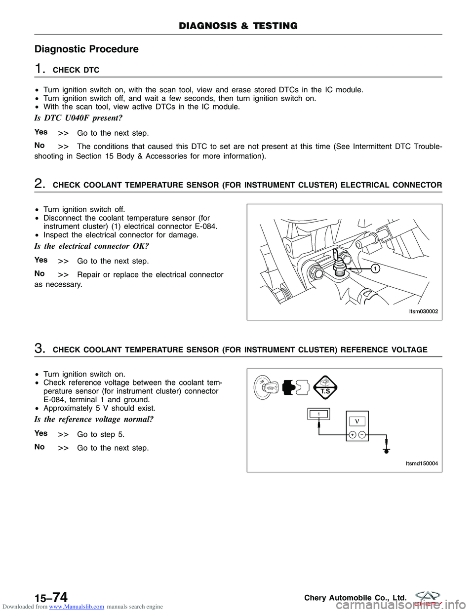
2.CHECK COOLANT TEMPERATURE SENSOR (FOR INSTRUMENT CLUSTER) ELECTRICAL CONNECTOR
• Turn ignition switch off.
• Disconnect the coolant temperature sensor (for
instrument cluster) (1) electrical connector E-084.
• Inspect the electrical connector for damage.
Is the electrical connector OK?
Ye s>>Go to the next step.
No
>>Repair or replace the electrical connector
as necessary.
3.CHECK COOLANT TEMPERATURE SENSOR (FOR INSTRUMENT CLUSTER) REFERENCE VOLTAGE
• Turn ignition switch on.
• Check reference voltage between the coolant tem-
perature sensor (for instrument cluster) connector
E-084, terminal 1 and ground.
• Approximately 5 V should exist.
Is the reference voltage normal?
Ye s>>Go to step 5.
No
>>Go to the next step.
DIAGNOSIS & TESTING
LTSM030002
LTSMD150004
15–74Chery Automobile Co., Ltd.
Page 1659 of 1903
Downloaded from www.Manualslib.com manuals search engine 4.CHECK COOLANT TEMPERATURE SENSOR (FOR INSTRUMENT CLUSTER) REFERENCE VOLTAGE
• Turn ignition switch off.
• Disconnect the IC module connector.
• Check harness for a short to ground.
• Check the coolant temperature sensor circuit for voltage.
COOLANT
TEMPERATURE SENSOR (FOR INSTRUMENT
CLUSTER) TERMINAL GROUND
1
Ground
• Check the coolant temperature sensor circuit for resistance.
COOLANT
TEMPERATURE SENSOR (FORINSTRUMENT CLUSTER)
TERMINAL IC TERMINAL CONTINUITY
13
1Yes
• Check harness for a short to power.
Is the check result normal?
Ye s>>Go to the next step.
No
>>Repair or replace the coolant temperature sensor (for instrument cluster) supply circuit as necessary.
DIAGNOSIS & TESTING
15
15–75Chery Automobile Co., Ltd.
Page 1660 of 1903
Downloaded from www.Manualslib.com manuals search engine 5.CHECK COOLANT TEMPERATURE METER INDICATOR
• Turn ignition switch off.
• Connect the IC connector.
• Connect the coolant temperature sensor (for instrument cluster) electrical connector E-084.
• Turn ignition switch on.
• With the scan tool, view active DTCs and data stream in the IC.
Is DTC U040F still present?
Ye s>>Replace the coolant temperature sensor (for instrument cluster).
With the scan tool, view active DTCs and data stream in the IC.
� If the DTC U040F is not present, the system is now normal.
� If the DTC U040F is present, go to the next step.
No
>>The system is now operating properly.
Reassemble the vehicle and verify the customers complaint is repaired.
6.CHECK DTC
• With the X-431 scan tool, read IC DTCs.
• Refer to �DTC Confirmation Procedure�.
Is DTC U040F still present?
Ye s>>Replace the IC.
No
>>The system is now operating properly.
Reassemble the vehicle and verify the customers complaint is repaired.
DIAGNOSIS & TESTING
15–76Chery Automobile Co., Ltd.
Page 1661 of 1903
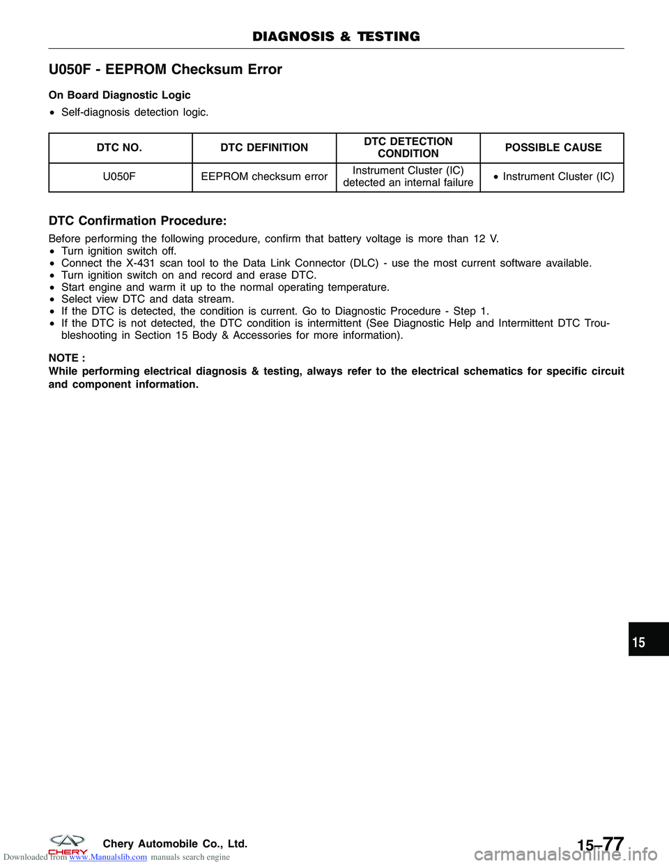
Downloaded from www.Manualslib.com manuals search engine U050F - EEPROM Checksum Error
On Board Diagnostic Logic
•Self-diagnosis detection logic.
DTC NO. DTC DEFINITION DTC DETECTION
CONDITION POSSIBLE CAUSE
U050F EEPROM checksum error Instrument Cluster (IC)
detected an internal failure •
Instrument Cluster (IC)
DTC Confirmation Procedure:
Before performing the following procedure, confirm that battery voltage is more than 12 V.
• Turn ignition switch off.
• Connect the X-431 scan tool to the Data Link Connector (DLC) - use the most current software available.
• Turn ignition switch on and record and erase DTC.
• Start engine and warm it up to the normal operating temperature.
• Select view DTC and data stream.
• If the DTC is detected, the condition is current. Go to Diagnostic Procedure - Step 1.
• If the DTC is not detected, the DTC condition is intermittent (See Diagnostic Help and Intermittent DTC Trou-
bleshooting in Section 15 Body & Accessories for more information).
NOTE :
While performing electrical diagnosis & testing, always refer to the electrical schematics for specific circuit
and component information.
DIAGNOSIS & TESTING
15
15–77Chery Automobile Co., Ltd.