Page 1717 of 1903
Downloaded from www.Manualslib.com manuals search engine On Board Diagnostic Logic
•Self-diagnosis detection logic.
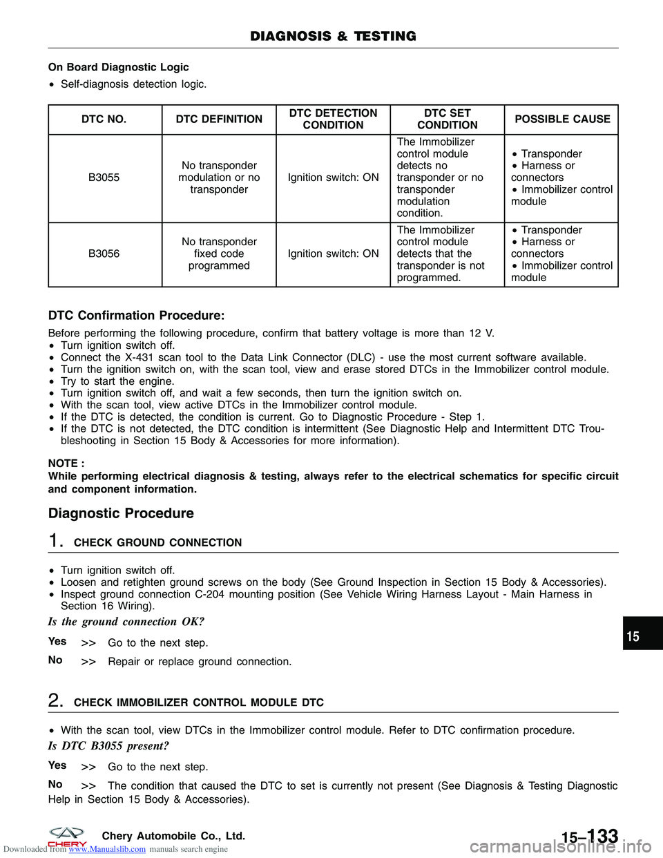
DTC NO. DTC DEFINITION DTC DETECTION
CONDITION DTC SET
CONDITION POSSIBLE CAUSE
B3055 No transponder
modulation or no transponder Ignition switch: ON The Immobilizer
control module
detects no
transponder or no
transponder
modulation
condition. •
Transponder
• Harness or
connectors
• Immobilizer control
module
B3056 No transponder
fixed code
programmed Ignition switch: ON The Immobilizer
control module
detects that the
transponder is not
programmed. •
Transponder
• Harness or
connectors
• Immobilizer control
module
DTC Confirmation Procedure:
Before performing the following procedure, confirm that battery voltage is more than 12 V.
• Turn ignition switch off.
• Connect the X-431 scan tool to the Data Link Connector (DLC) - use the most current software available.
• Turn the ignition switch on, with the scan tool, view and erase stored DTCs in the Immobilizer control module.
• Try to start the engine.
• Turn ignition switch off, and wait a few seconds, then turn the ignition switch on.
• With the scan tool, view active DTCs in the Immobilizer control module.
• If the DTC is detected, the condition is current. Go to Diagnostic Procedure - Step 1.
• If the DTC is not detected, the DTC condition is intermittent (See Diagnostic Help and Intermittent DTC Trou-
bleshooting in Section 15 Body & Accessories for more information).
NOTE :
While performing electrical diagnosis & testing, always refer to the electrical schematics for specific circuit
and component information.
Diagnostic Procedure
1.CHECK GROUND CONNECTION
• Turn ignition switch off.
• Loosen and retighten ground screws on the body (See Ground Inspection in Section 15 Body & Accessories).
• Inspect ground connection C-204 mounting position (See Vehicle Wiring Harness Layout - Main Harness in
Section 16 Wiring).
Is the ground connection OK?
Ye s>>Go to the next step.
No
>>Repair or replace ground connection.
2.CHECK IMMOBILIZER CONTROL MODULE DTC
• With the scan tool, view DTCs in the Immobilizer control module. Refer to DTC confirmation procedure.
Is DTC B3055 present?
Ye s>>Go to the next step.
No
>>The condition that caused the DTC to set is currently not present (See Diagnosis & Testing Diagnostic
Help in Section 15 Body & Accessories).
DIAGNOSIS & TESTING
15
15–133Chery Automobile Co., Ltd.
Page 1718 of 1903
Downloaded from www.Manualslib.com manuals search engine 3.CHECK IMMOBILIZER CONTROL MODULE ELECTRICAL CONNECTOR
• Turn ignition switch off.
• Disconnect the Immobilizer control module electrical
connectors C-026 (1).
• Inspect the electrical connector for damage.
Is the electrical connector OK?
Ye s>>Go to the next step.
No
>>Repair or replace the electrical connector
as necessary.
4.CHECK IMMOBILIZER COIL
• Check the resistance of the Immobilizer coil between the Immobilizer coil connector C-026, pin 9 and pin 11.
IMMOBILIZER COIL
TERMINAL IMMOBILIZER COIL
TERMINAL
91 1
Is the resistance range from 5 to 20 ohms?
Ye s>>Go to the next step.
No
>>Replace the Immobilizer coil.
DIAGNOSIS & TESTING
LTSMD150019
15–134Chery Automobile Co., Ltd.
Page 1719 of 1903
Downloaded from www.Manualslib.com manuals search engine 5.CHECK IMMOBILIZER COIL
• Check the resistance of the Immobilizer coil between the Immobilizer coil connector C-026, pin 9 and pin 10.
• Check the resistance of the Immobilizer coil between the Immobilizer coil connector C-026, pin 11 and pin 10.
IMMOBILIZER
COIL
TERMINAL IMMOBILIZER
COIL
TERMINAL CONTINUITY
91
0
Not
11 1 0
• Continuity should not exist.
Is the check result normal?
Ye s>>Go to the next step.
No
>>Replace the Immobilizer coil.
6.REPLACE AND PROGRAM TRANSPONDER
• Reconnect the Immobilizer control module electrical
connector C-026.
• Replace the chip (1) with a new one.
DIAGNOSIS & TESTING
VISMD150018
15
15–135Chery Automobile Co., Ltd.
Page 1724 of 1903
Downloaded from www.Manualslib.com manuals search engine Diagnostic Procedure
1.CHECK GROUND CONNECTION
• Turn ignition switch off.
• Loosen and retighten ground screws on the body (See Ground Inspection in Section 15 Body & Accessories).
• Inspect ground connection C-204 mounting position (See Vehicle Wiring Harness Layout - Main Harness in
Section 16 Wiring).
Is the ground connection OK?
Ye s>>Go to the next step.
No
>>Repair or replace ground connection.
2.CHECK IMMOBILIZER CONTROL MODULE DTC
• With the scan tool, view DTCs in the Immobilizer control module. Refer to DTC confirmation procedure.
Is DTC B3060, B3061 or B3077 present?
Ye s>>For DTC B3060, go to step 5.
For DTC B3061, go to the next step.
For DTC B3077, go to step 6.
No
>>The condition that caused the DTC is currently not present. Monitor the scan tool data relative to this
circuit while wiggle testing the wiring and connectors and looking for the DTC to reset. Using the wiring schematic as a guide, inspect the related wiring and connectors of the Immobilizer
control module.
Verify that there is good terminal contact in the related connectors.
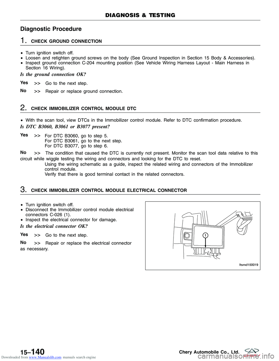
3.CHECK IMMOBILIZER CONTROL MODULE ELECTRICAL CONNECTOR
• Turn ignition switch off.
• Disconnect the Immobilizer control module electrical
connectors C-026 (1).
• Inspect the electrical connector for damage.
Is the electrical connector OK?
Ye s>>Go to the next step.
No
>>Repair or replace the electrical connector
as necessary.
DIAGNOSIS & TESTING
LTSMD150019
15–140Chery Automobile Co., Ltd.
Page 1725 of 1903
Downloaded from www.Manualslib.com manuals search engine 4.CHECK THE IMMOBILIZER COIL
• Check the resistance of the Immobilizer coil between the Immobilizer coil connector C-026, pin 9 and pin 11.
IMMOBILIZER COIL
TERMINAL IMMOBILIZER COIL
TERMINAL
91 1
Is the resistance range from 5 to 20 ohms?
Ye s>>Go to the next step.
No
>>Replace the Immobilizer coil.
5.CHECK IMMOBILIZER COIL
• Check the resistance between the Immobilizer coil connector C-026, pin 9 and pin 10.
• Check the resistance between the Immobilizer coil connector C-026, pin 11 and pin 10.
IMMOBILIZER
COIL
TERMINAL IMMOBILIZER
COIL
TERMINAL CONTINUITY
91
0
Not
11 1 0
Is the check result normal?
Ye s>>Go to the next step.
No
>>Replace the Immobilizer coil.
DIAGNOSIS & TESTING
15
15–141Chery Automobile Co., Ltd.
Page 1756 of 1903
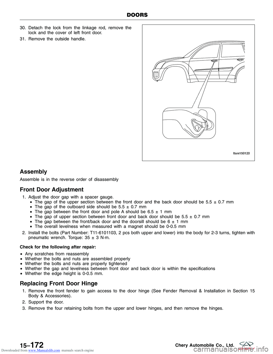
Downloaded from www.Manualslib.com manuals search engine 30. Detach the lock from the linkage rod, remove thelock and the cover of left front door.
31. Remove the outside handle.
Assembly
Assemble is in the reverse order of disassembly
Front Door Adjustment
1. Adjust the door gap with a spacer gauge. •The gap of the upper section between the front door and the back door should be 5.5 ± 0.7 mm
• The gap of the outboard side should be 5.5 ± 0.7 mm
• The gap between the front door and pole A should be 6.5±1mm
• The gap of upper section between front door and back door should be 5.5 ± 0.7 mm
• The gap between the front/back door and the doorsill should be6±1mm
• The overall levelness when measured with a magnet should be 0-0.5 mm
2. Install the bolts (Part Number: T11-6101103, 2 pcs both upper and lower) into the body for 2-3 turns, tighten with pneumatic wrench. Torque: 35 ± 3 N·m.
Check for the following after repair:
• Any scratches from reassembly
• Whether the bolts and nuts are assembled properly
• Whether the bolts and nuts are properly tightened
• Whether the gap and levelness between front door and back door is within the specifications
• Whether the edge height is 0-0.5 mm.
Replacing Front Door Hinge
1. Remove the front fender to gain access to the door hinge (See Fender Removal & Installation in Section 15
Body & Accessories).
2. Support the door.
3. Remove the four retaining bolts from the upper and lower hinges, and then remove the hinges.
DOORS
LTSM150120
15–172Chery Automobile Co., Ltd.
Page 1758 of 1903
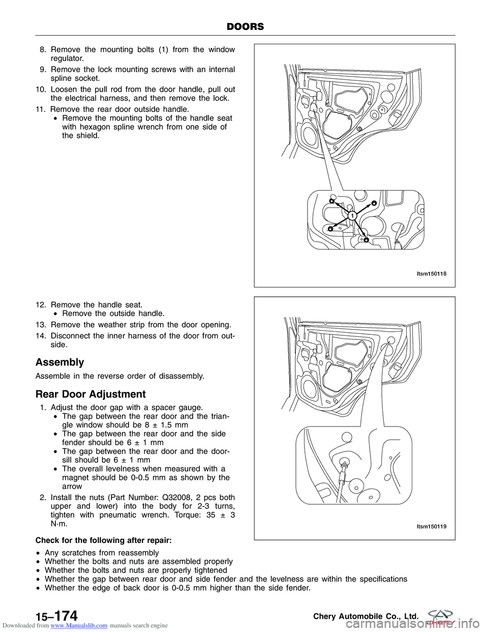
Downloaded from www.Manualslib.com manuals search engine 8. Remove the mounting bolts (1) from the windowregulator.
9. Remove the lock mounting screws with an internal spline socket.
10. Loosen the pull rod from the door handle, pull out the electrical harness, and then remove the lock.
11. Remove the rear door outside handle. •Remove the mounting bolts of the handle seat
with hexagon spline wrench from one side of
the shield.
12. Remove the handle seat. •Remove the outside handle.
13. Remove the weather strip from the door opening.
14. Disconnect the inner harness of the door from out- side.
Assembly
Assemble in the reverse order of disassembly.
Rear Door Adjustment
1. Adjust the door gap with a spacer gauge.•The gap between the rear door and the trian-
gle window should be 8 ± 1.5 mm
• The gap between the rear door and the side
fender should be6±1mm
• The gap between the rear door and the door-
sill should be6±1mm
• The overall levelness when measured with a
magnet should be 0-0.5 mm as shown by the
arrow
2. Install the nuts (Part Number: Q32008, 2 pcs both upper and lower) into the body for 2-3 turns,
tighten with pneumatic wrench. Torque: 35 ± 3
N·m.
Check for the following after repair:
• Any scratches from reassembly
• Whether the bolts and nuts are assembled properly
• Whether the bolts and nuts are properly tightened
• Whether the gap between rear door and side fender and the levelness are within the specifications
• Whether the edge of back door is 0-0.5 mm higher than the side fender.
DOORS
LTSM150118
LTSM150119
15–174Chery Automobile Co., Ltd.
Page 1759 of 1903
Downloaded from www.Manualslib.com manuals search engine Replacing Rear Door Hinge
1. Remove the door check bolts.
2. Support the door.
3. Remove the four retaining bolts from the upper and lower hinges, and then remove the hinges.
Back Cargo Door
Removal & Installation
1. Remove the two back cargo door bolts connecting the back door and hinge.(Tighten: Bolts connecting the back door and hinge to 50 ± 5 N·m)
(Tighten: Bolts connecting the hinge and body to 36 ± 4 N·m)
2. Disconnect the wiring harness electrical connector.
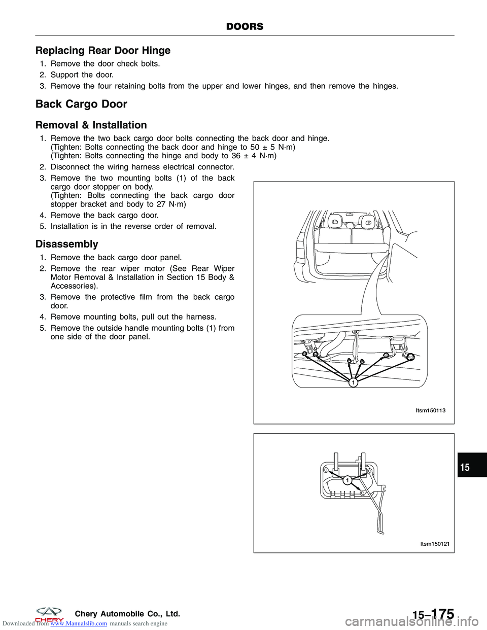
3. Remove the two mounting bolts (1) of the back cargo door stopper on body.
(Tighten: Bolts connecting the back cargo door
stopper bracket and body to 27 N·m)
4. Remove the back cargo door.
5. Installation is in the reverse order of removal.
Disassembly
1. Remove the back cargo door panel.
2. Remove the rear wiper motor (See Rear Wiper Motor Removal & Installation in Section 15 Body &
Accessories).
3. Remove the protective film from the back cargo door.
4. Remove mounting bolts, pull out the harness.
5. Remove the outside handle mounting bolts (1) from one side of the door panel.
DOORS
LTSM150113
LTSM150121
15
15–175Chery Automobile Co., Ltd.