Page 1761 of 1903
Downloaded from www.Manualslib.com manuals search engine Assembly
Assembly is in the reverse order of disassembly.
Back Cargo Door Adjustment
1. Adjust the door gap with a spacer gauge.•The gap between the back cargo door and the upper part of the side fender should be 5.8±1mm
• The gap between the back cargo door and the middle part of the side fender should be 6.4±1mm
• The gap between the back cargo door and the tail lamp should be 6.2±1mm
• The gap between the rear and head cover should be 9.3 ± 1.5 mm
• The overall levelness when measured with a magnet should be 0-0.5 mm
2. Install the nuts (Part Number: T11-6301011, 2 pcs both upper and lower) into the body for 2-3 turns, tighten with pneumatic wrench. Torque: 50 ± 3 N·m.
Check for the following after repair:
• Any scratches from reassembly
• Whether the bolts and nuts are assembled properly
• Whether the bolts and nuts are properly tightened
• Whether the gap and levelness between back cargo door and side fenders are within the specifications
Replacing Rear Door Hinge
1. Remove the door check bolts.
2. Support the door.
3. Remove the four retaining bolts from the upper and lower hinges, and then remove the hinges.
DOORS
15
15–177Chery Automobile Co., Ltd.
Page 1774 of 1903
Downloaded from www.Manualslib.com manuals search engine Headlamp Adjustment Procedure
NOTE :
Follow all local laws and regulations and verify the following items before adjustment:1. Check the following before starting the headlamp adjustment procedure: •All tires are filled to the proper tire pressure.
• The vehicle is unloaded (except for spare tire and tools, and include driver’s weight for sedan).
• The vehicle should be parked on a level surface.
• The headlights are clean.
• The headlights are working properly.
2. Park the vehicle on a level surface approximately 10 meters from the vertical wall or screen directly in front of it. NOTE: The vertical wall or screen must be a minimum of 2.4 meters wide.
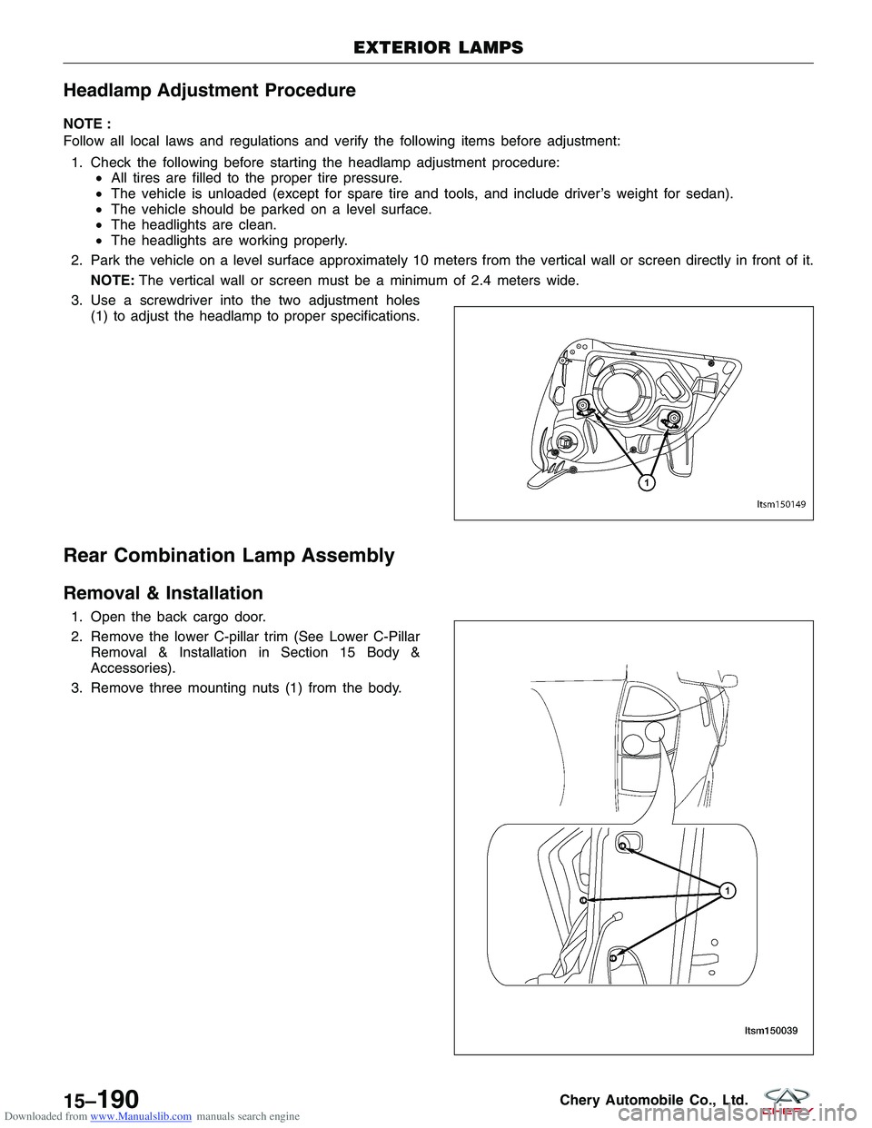
3. Use a screwdriver into the two adjustment holes (1) to adjust the headlamp to proper specifications.
Rear Combination Lamp Assembly
Removal & Installation
1. Open the back cargo door.
2. Remove the lower C-pillar trim (See Lower C-PillarRemoval & Installation in Section 15 Body &
Accessories).
3. Remove three mounting nuts (1) from the body.
EXTERIOR LAMPS
LTSM150149
LTSM150039
15–190Chery Automobile Co., Ltd.
Page 1786 of 1903
Downloaded from www.Manualslib.com manuals search engine HOOD
Hood
Removal & Installation
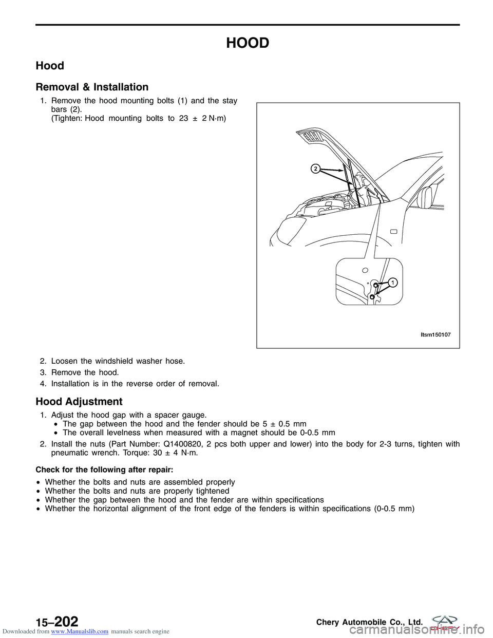
1. Remove the hood mounting bolts (1) and the staybars (2).
(Tighten: Hood mounting bolts to 23 ± 2 N·m)
N·m)
2. Loosen the windshield washer hose.
3. Remove the hood.
4. Installation is in the reverse order of removal.
Hood Adjustment
1. Adjust the hood gap with a spacer gauge. •The gap between the hood and the fender should be 5 ± 0.5 mm
• The overall levelness when measured with a magnet should be 0-0.5 mm
2. Install the nuts (Part Number: Q1400820, 2 pcs both upper and lower) into the body for 2-3 turns, tighten with pneumatic wrench. Torque: 30 ± 4 N·m.
Check for the following after repair:
• Whether the bolts and nuts are assembled properly
• Whether the bolts and nuts are properly tightened
• Whether the gap between the hood and the fender are within specifications
• Whether the horizontal alignment of the front edge of the fenders is within specifications (0-0.5 mm)
LTSM150107
15–202Chery Automobile Co., Ltd.
Page 1805 of 1903
Downloaded from www.Manualslib.com manuals search engine 11. Applying the bonding agent:•Cut off the pot tip and fill the bonding agent
into the pot.
• Place the pot into the sealant gun.
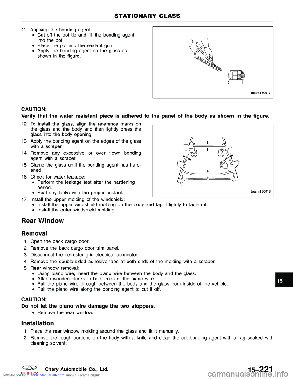
• Apply the bonding agent on the glass as
shown in the figure.
CAUTION:
Verify that the water resistant piece is adhered to the panel of the body as shown in the figure.
12. To install the glass, align the reference marks on
the glass and the body and then lightly press the
glass into the body opening.
13. Apply the bonding agent on the edges of the glass with a scraper.
14. Remove any excessive or over flown bonding agent with a scraper.
15. Clamp the glass until the bonding agent has hard- ened.
16. Check for water leakage: •Perform the leakage test after the hardening
period.
• Seal any leaks with the proper sealant.
17. Install the upper molding of the windshield: •Install the upper windshield molding on the body and tap it lightly to fasten it.
• Install the outer windshield molding.
Rear Window
Removal
1. Open the back cargo door.
2. Remove the back cargo door trim panel.
3. Disconnect the defroster grid electrical connector.
4. Remove the double-sided adhesive tape at both ends of the molding with a scraper.
5. Rear window removal:
•Using piano wire, insert the piano wire between the body and the glass.
• Attach wooden blocks to both ends of the piano wire.
• Pull the piano wire through between the body and the glass from inside of the vehicle.
• Pull the piano wire along the bonding agent to cut it off.
CAUTION:
Do not let the piano wire damage the two stoppers.
•Remove the rear window.
Installation
1. Place the rear window molding around the glass and fit it manually.
2. Remove the rough portions on the body with a knife and clean the cut bonding agent with a rag soaked with
cleaning solvent.
STATIONARY GLASS
BESM150017
BESM150018
15
15–221Chery Automobile Co., Ltd.
Page 1807 of 1903
Downloaded from www.Manualslib.com manuals search engine 11. To install the glass, align the reference marks onthe glass and the body and then lightly press the
glass into the body opening.
12. Apply the bonding agent on the edges of the glass with a scraper.
13. Remove any excessive or over flown bonding agent with a scraper.
14. Clamp the glass until the bonding agent has hard- ened.
15. Check for water leakage: •Perform the leakage test after the hardening
period.
• Seal any leaks with the proper sealant.
16. Install the rear window molding: •Install the rear window outer lower molding on the body and tap it lightly to fasten it.
• Connect the leads of the rear window defroster.
STATIONARY GLASS
BESM150018
15
15–223Chery Automobile Co., Ltd.
Page 1813 of 1903
Downloaded from www.Manualslib.com manuals search engine ON-VEHICLE SERVICE
Sunroof Glass
Removal & Installation
1. Operate the sunroof switch to lift the sunroof to the full tilt position.
2. Push the inner trim strip (side cover inner LH/RH) rearwards to remove.
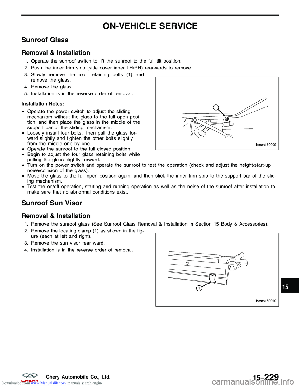
3. Slowly remove the four retaining bolts (1) andremove the glass.
4. Remove the glass.
5. Installation is in the reverse order of removal.
Installation Notes:
• Operate the power switch to adjust the sliding
mechanism without the glass to the full open posi-
tion, and then place the glass in the middle of the
support bar of the sliding mechanism.
• Loosely install four bolts. Then pull the glass for-
ward slightly and tighten the other bolts slightly
from the middle one by one.
• Operate the sunroof to the full closed position.
• Begin to adjust the four glass retaining bolts while
pulling the glass slightly forward.
• Turn on the power switch and operate the sunroof to test the operation (check and adjust the height/start-up
noise/collision of the glass).
• Move the glass to the full open position again, and then stick the inner trim strip to the support bar of the slid-
ing mechanism.
• Test the on/off operation, starting and running operation as well as the noise of the sunroof after installation to
make sure that no abnormal conditions exist.
Sunroof Sun Visor
Removal & Installation
1. Remove the sunroof glass (See Sunroof Glass Removal & Installation in Section 15 Body & Accessories).
2. Remove the locating clamp (1) as shown in the fig-
ure (each at left and right).
3. Remove the sun visor rear ward.
4. Installation is in the reverse order of removal.
BESM150009
BESM150010
15
15–229Chery Automobile Co., Ltd.
Page 1831 of 1903
Downloaded from www.Manualslib.com manuals search engine ELECTRICAL TROUBLESHOOTING
Troubleshooting Wiring Problems
When troubleshooting wiring problems there are six steps which can aid in the procedure. The steps are listed and
explained below. Always check for non-factory equipped components added to the vehicle before doing any diagno-
sis. If the vehicle is equipped with these items, disconnect them to verify these add-on items are not the cause of the
problem.
Perform the following when troubleshooting a wiring problem:1. Verify the problem.
2. Verify any related symptoms (do this by performing operational checks on components that are in the same circuit).
3. Analyze the symptoms (use the wiring diagrams to determine what the circuit is doing, where the problem most likely is occurring and where the diagnosis will continue).
4. Isolate the problem area.
5. Repair the problem area.
6. Verify the proper operation (for this step, check for proper operation of all items on the repaired circuit).
Testing For Voltage
1. Connect the ground lead of a voltmeter to a known good ground.
2. Connect the other lead of the voltmeter to the selected test point. The vehicle ignition may need to be turned ON to check voltage. Refer to the appropriate test procedure.
Testing For Continuity
1. Remove the fuse for the circuit being checked or, disconnect the battery.
2. Connect one lead of the ohmmeter to one side of the circuit being tested.
3. Connect the other lead to the other end of the circuit being tested (low or no resistance means good continuity).
Testing For A Short To Ground
1. Remove the fuse and disconnect all items involved with the fuse.
2. Connect a test light or a voltmeter across the terminals of the fuse.
3. Starting at the fuse block, wiggle the wiring harness about six to eight inches apart and watch the voltmeter/testlight.
4. If the voltmeter registers voltage or the test light glows, there is a short to ground in that general area of the wiring harness.
Intermittent and Poor Connections
Most intermittent electrical problems are caused by faulty electrical connections or wiring. It is also possible for a
sticking component or relay to cause a problem. Before condemning a component or wiring assembly, check the
following items:
1. Connectors are fully seated
2. Spread terminals, or terminal push out
3. Terminals in the wiring assembly are fully seated into the connector/component and locked into position
4. Dirt or corrosion on the terminals (any amount of corrosion or dirt could cause an intermittent problem)
5. Damaged connector/component casing exposing the item to dirt or moisture
6. Wire insulation that has rubbed through causing a short to ground
7. Some or all of the wiring strands broken inside of the insulation
8. Wiring broken inside of the insulation
16
16–5Chery Automobile Co., Ltd.
Page 1833 of 1903
Downloaded from www.Manualslib.com manuals search engine Ohmmeter
•The ohmmeter is used to measure the resistance
between two points in a circuit and to check for
continuity and short circuits.
CAUTION:
Do not connect the ohmmeter to any circuit
where voltage is applied. This will damage the
ohmmeter.
ELECTRICAL TROUBLESHOOTING TOOLS
BESM010028
16
16–7Chery Automobile Co., Ltd.