Page 1220 of 1903
Downloaded from www.Manualslib.com manuals search engine 8. Install the transaxle housing.
9. Applya1mmto1.2mmdiameter of sealant onthe specified position of the transaxle housing.
CAUTION:
The sealant line applied should be uniform and
continuous and without breaks.
10. Tighten the transaxle housing bolts to the specified torque.
11. Install the bottom transaxle cover.
12. Applya1mmto1.2mmdiameter of sealant on the specified position of the transaxle housing.
CAUTION:
The sealant line applied should be uniform and
continuous and without breaks.
13. Apply transaxle fluid to the O-ring of speed sensor.(Transaxle fluid: 75W-90)
MANUAL TRANSAXLE UNIT REPAIR
LTSM080032
LTSM080033
LTSM080034
08
08–277Chery Automobile Co., Ltd.
Page 1221 of 1903
Downloaded from www.Manualslib.com manuals search engine 14. Install the vehicle speed sensor.
15. Install the gear shifting arm assembly. Apply lubri-cating fluid on the contact surface of the gear shift-
ing drive slider and the gear shifting arm assembly.
(The specified lubricating fluid: Mobilux Ep2)
STATUS OF SWITCH CIRCUIT
Pressed Off
Released On
16. Inspect the backup lamp switch. Inspect the switch for broken terminal or an open circuit.
Input Shaft
Specifications
Clearance Specifications
SYNCHRONIZER RING VALUE OF A (mm)WEARING LIMIT
1st-2nd Gear 1.10 - 1.170.05 mm
3rd-4th Gear 1.35 - 1.900.05 mm
5th Gear 1.10 - 1.170.05 mm
MANUAL TRANSAXLE UNIT REPAIR
LTSM080035
LTSM080036
08–278Chery Automobile Co., Ltd.
Page 1279 of 1903
Downloaded from www.Manualslib.com manuals search engine ON-VEHICLE SERVICE
Front Hub and Bearing
Removal & Installation
NOTE :
The following special tools are required to perform the repair procedure:
•Bearing Puller
1. Raise and support the vehicle.
2. Remove the wheel mounting nuts and the tire and wheel assembly. (Tighten: Wheel mounting nuts to 110 N·m)
3. Remove the front axle hub nut (1) from the front knuckle.
(Tighten: Front axle hub nut to 135 N·m)
4. Remove the front brake rotor (See Front Brake Rotor Removal & Installation in Section 12 Brakes).
5. Remove the wheel speed sensor mounting bolt (1), then remove the wheel speed sensor.
6. Using the bearing puller, remove the wheel hub bearing from the knuckle.
7. Installation is in the reverse order of removal.
LTSM090006
LTSM100045
LTSM090003
09
09–5Chery Automobile Co., Ltd.
Page 1280 of 1903
Downloaded from www.Manualslib.com manuals search engine Front Axle Shaft
Removal & Installation
1. Raise and support the vehicle.
2. Remove the wheel mounting nuts and the tire and wheel assembly.(Tighten: Wheel mounting nuts to 110 N·m)
3. Remove the front axle hub nut (1) from the front knuckle.
(Tighten: Front axle hub nut to 135 N·m)
4. Remove the wheel speed sensor bolt (1), then remove wheel speed sensor.
5. Remove the brake caliper adapter to steering knuckle mounting bolts. (Tighten: Brake caliper adapter mounting bolts to 85 N·m)
6. Remove the brake caliper adapter (with the brake caliper still attached).
1 - Left Half Shaft2 - Right Half Shaft
ON-VEHICLE SERVICE
LTSM090002
LTSM090006
LTSM100045
09–6Chery Automobile Co., Ltd.
Page 1286 of 1903
Downloaded from www.Manualslib.com manuals search engine ON-VEHICLE SERVICE
Rear Hub and Bearing
Removal & Installation
1. Raise and support the vehicle.
2. Remove the wheel mounting nuts and the tire and wheel assembly.(Tighten: Wheel mounting nuts to 110 N·m)
3. Disconnect the ABS wheel speed sensor electrical connector.
4. While an assistant applies the brakes (to keep the hub from rotating), remove the hub nut from the axle half shaft.
(Tighten: Hub nut to 135 N·m)
5. Remove the rear brake rotor (See Rear Brake Rotor Removal & Installation in Section 12 Brakes).
6. Remove the hub and bearing mounting nuts (1). (Tighten: Hub and bearing mounting nuts to 65
N·m)
7. Take out the rear hub and bearing.
8. Installation is in the reverse order of the removal.
LTSM090001
09–12Chery Automobile Co., Ltd.
Page 1292 of 1903

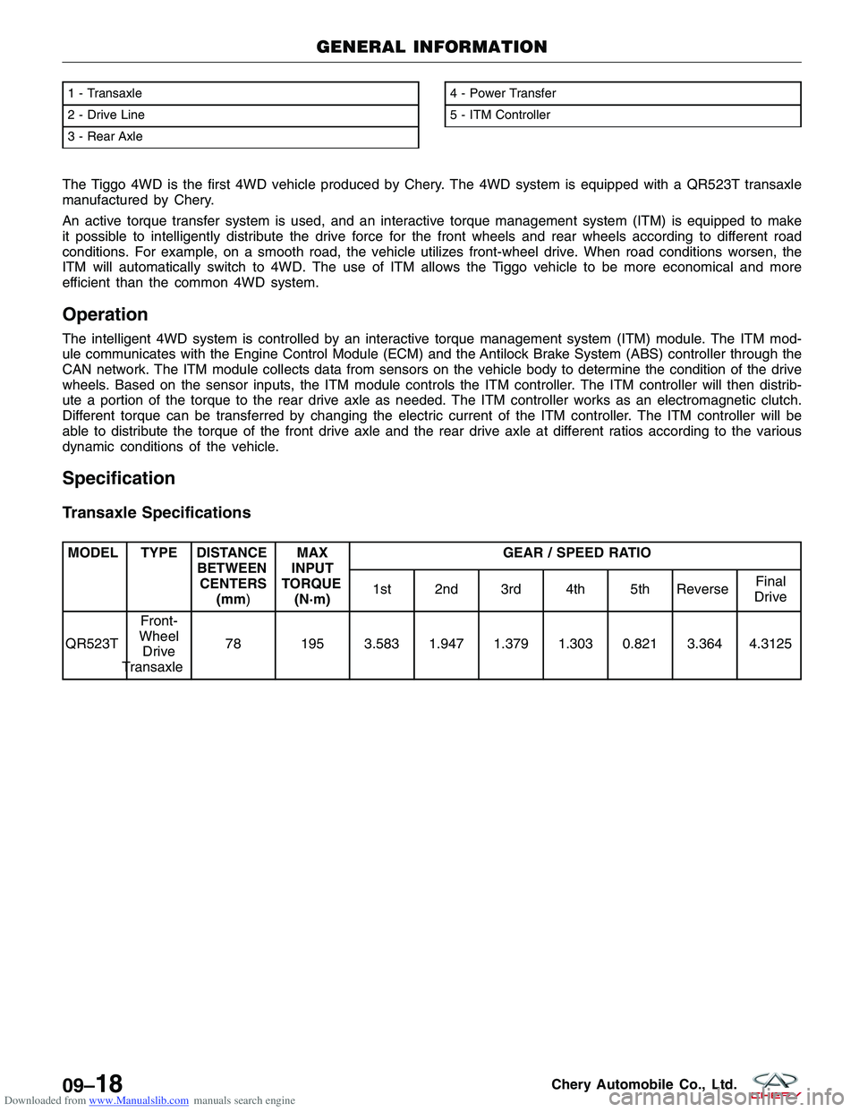
Downloaded from www.Manualslib.com manuals search engine The Tiggo 4WD is the first 4WD vehicle produced by Chery. The 4WD system is equipped with a QR523T transaxle
manufactured by Chery.
An active torque transfer system is used, and an interactive torque management system (ITM) is equipped to make
it possible to intelligently distribute the drive force for the front wheels and rear wheels according to different road
conditions. For example, on a smooth road, the vehicle utilizes front-wheel drive. When road conditions worsen, the
ITM will automatically switch to 4WD. The use of ITM allows the Tiggo vehicle to be more economical and more
efficient than the common 4WD system.
Operation
The intelligent 4WD system is controlled by an interactive torque management system (ITM) module. The ITM mod-
ule communicates with the Engine Control Module (ECM) and the Antilock Brake System (ABS) controller through the
CAN network. The ITM module collects data from sensors on the vehicle body to determine the condition of the drive
wheels. Based on the sensor inputs, the ITM module controls the ITM controller. The ITM controller will then distrib-
ute a portion of the torque to the rear drive axle as needed. The ITM controller works as an electromagnetic clutch.
Different torque can be transferred by changing the electric current of the ITM controller. The ITM controller will be
able to distribute the torque of the front drive axle and the rear drive axle at different ratios according to the various
dynamic conditions of the vehicle.
Specification
Transaxle Specifications
MODEL TYPE DISTANCEBETWEENCENTERS (mm) MAX
INPUT
TORQUE (N·m) GEAR / SPEED RATIO
1st 2nd 3rd 4th 5th Reverse Final
Drive
QR523T Front-
Wheel Drive
Transaxle 78 195 3.583 1.947 1.379 1.303 0.821 3.364 4.3125
1 - Transaxle
2 - Drive Line
3 - Rear Axle4 - Power Transfer
5 - ITM Controller
GENERAL INFORMATION
LTSM160027
09–18Chery Automobile Co., Ltd.
Page 1293 of 1903

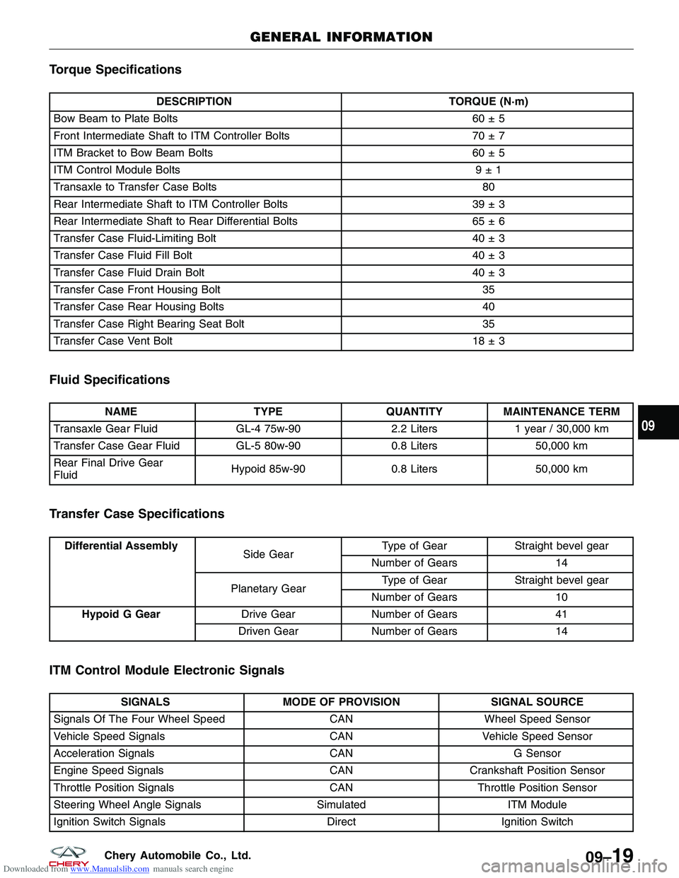
Downloaded from www.Manualslib.com manuals search engine Torque Specifications
DESCRIPTIONTORQUE (N·m)
Bow Beam to Plate Bolts 60 ± 5
Front Intermediate Shaft to ITM Controller Bolts 70 ± 7
ITM Bracket to Bow Beam Bolts 60 ± 5
ITM Control Module Bolts 9 ± 1
Transaxle to Transfer Case Bolts 80
Rear Intermediate Shaft to ITM Controller Bolts 39 ± 3
Rear Intermediate Shaft to Rear Differential Bolts 65 ± 6
Transfer Case Fluid-Limiting Bolt 40 ± 3
Transfer Case Fluid Fill Bolt 40 ± 3
Transfer Case Fluid Drain Bolt 40 ± 3
Transfer Case Front Housing Bolt 35
Transfer Case Rear Housing Bolts 40
Transfer Case Right Bearing Seat Bolt 35
Transfer Case Vent Bolt 18 ± 3
Fluid Specifications
NAMETYPEQUANTITYMAINTENANCE TERM
Transaxle Gear Fluid GL-4 75w-902.2 Liters1 year / 30,000 km
Transfer Case Gear Fluid GL-5 80w-900.8 Liters50,000 km
Rear Final Drive Gear
Fluid Hypoid 85w-90
0.8 Liters50,000 km
Transfer Case Specifications
Differential Assembly
Side GearType of Gear Straight bevel gear
Number of Gears 14
Planetary Gear Type of Gear
Straight bevel gear
Number of Gears 10
Hypoid G Gear Drive GearNumber of Gears 41
Driven Gear Number of Gears 14
ITM Control Module Electronic Signals
SIGNALSMODE OF PROVISION SIGNAL SOURCE
Signals Of The Four Wheel Speed CANWheel Speed Sensor
Vehicle Speed Signals CANVehicle Speed Sensor
Acceleration Signals CANG Sensor
Engine Speed Signals CANCrankshaft Position Sensor
Throttle Position Signals CANThrottle Position Sensor
Steering Wheel Angle Signals SimulatedITM Module
Ignition Switch Signals DirectIgnition Switch
GENERAL INFORMATION
09
09–19Chery Automobile Co., Ltd.
Page 1309 of 1903
Downloaded from www.Manualslib.com manuals search engine 4. While a helper applies the brakes to keep the hubfrom rotating, remove the front axle shaft nut (1).
(Tighten: Front axle shaft nut to 135 N·m)
5. Access and remove the front brake rotor (See Front Brake Rotor Remove & Installation in Section 12 Brakes).
6. Remove the wheel speed sensor mounting bolt (1). (Tighten: Wheel speed sensor mounting bolt to 10
± 1 N·m)
7. Remove the wheel speed sensor and set it aside.
8. Remove the lower ball joint mounting nut (1) attaching the lower control arm to the knuckle.
(Tighten: Control arm to steering knuckle nut to
120 ± 10 N·m)
9. Remove the nut (1) attaching the outer tie rod end to the steering knuckle.
(Tighten: Outer tie rod end nut to 32 - 38 N·m)
ON-VEHICLE SERVICE
LTSM090006
LTSM100045
LTSM100006
LTSM110034
10–8Chery Automobile Co., Ltd.