Page 1315 of 1903

Downloaded from www.Manualslib.com manuals search engine Operation
The strut assembly cushions the ride of the vehicle, controlling vibration, jounce and rebound of the suspension. The
coil spring controls ride quality and maintains proper ride height. The spring isolators isolate the coil spring at the top
and bottom from coming into metal-to-metal contact with the upper mounting seat and the strut. The strut dampens
jounce and rebound motions of the coil spring and suspension.
Diagnosis & Testing
Before removing the front strut, perform the following to test the front strut functionality:
•Adjust the tire pressure to all tires to proper specifications.
• Push and shake the front of the vehicle three or four times with identical force every time
• During the pushing and recoiling, the resistance and recoil times of the vehicle should be equal.
• If the strut (shock absorber) functions properly, the vehicle will recoil several times and then stop recoiling after
the pushing force is removed.
Removal & Installation
1. Raise and support the vehicle.
2. Remove the wheel mounting nuts and the wheel assembly.
(Tighten: Wheel mounting nuts to 110 N·m)
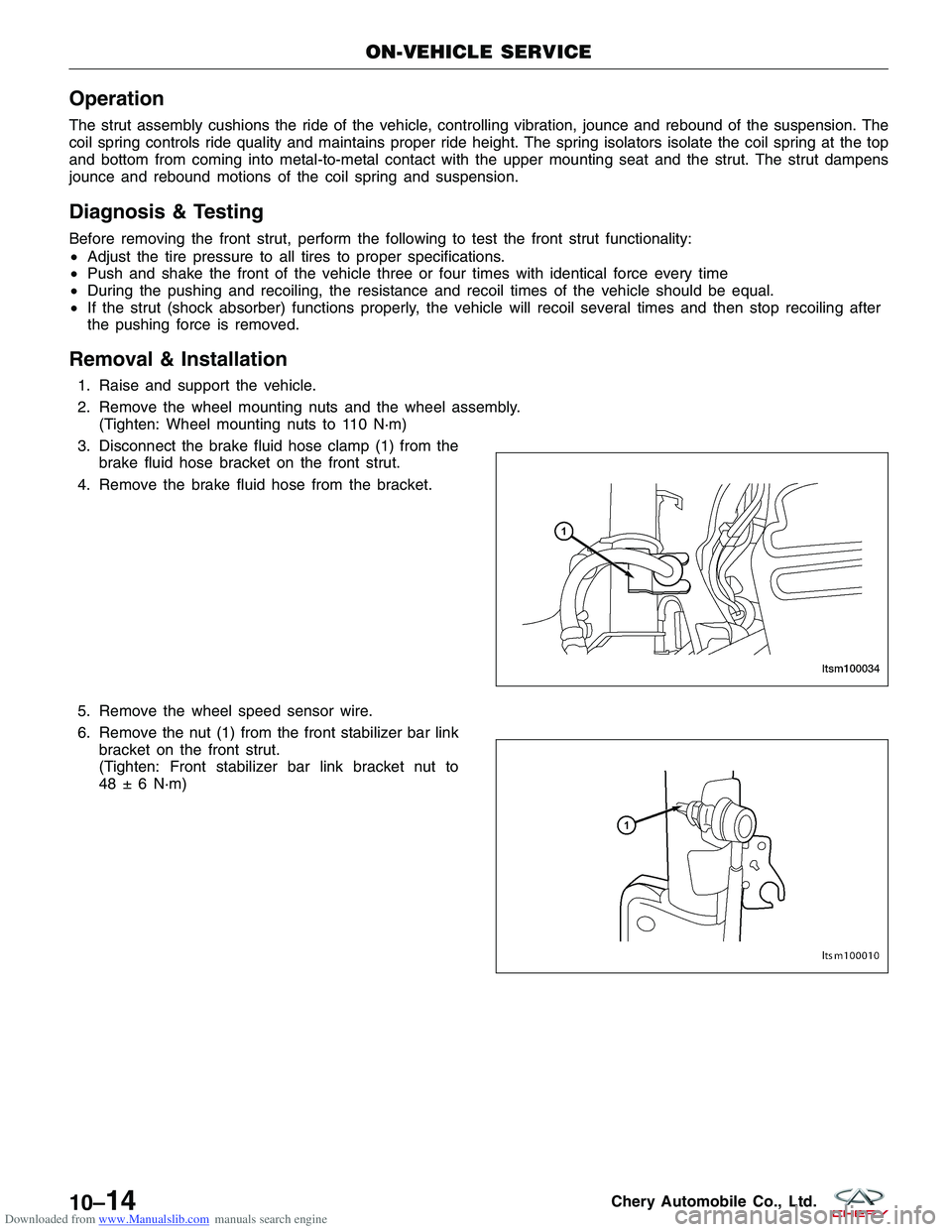
3. Disconnect the brake fluid hose clamp (1) from the brake fluid hose bracket on the front strut.
4. Remove the brake fluid hose from the bracket.
5. Remove the wheel speed sensor wire.
6. Remove the nut (1) from the front stabilizer bar link bracket on the front strut.
(Tighten: Front stabilizer bar link bracket nut to
48 ± 6 N·m)
ON-VEHICLE SERVICE
LTSM100034
LTSM100010
10–14Chery Automobile Co., Ltd.
Page 1319 of 1903
Downloaded from www.Manualslib.com manuals search engine 6. Remove the nut (1) between the control arm andthe steering knuckle.
(Tighten: Control arm to steering knuckle nut to
120 ± 10 N·m)
7. Remove the wheel speed sensor mounting bolt (1). (Tighten: Wheel speed sensor mounting bolt to 10
± 1 N·m)
8. Remove the wheel speed sensor and set it aside.
9. Remove the left and right front stabilizer bar links (See Front Stabilizer Bar Link Removal & Installation in Sec- tion 10 Suspension).
10. Remove the nut (1) attaching the outer tie rod ends to the steering knuckle on each side of the steering
rack.
(Tighten: Outer tie rod end nut to 35 N·m)
11. Remove the exhaust pipe assembly mounting bolts (1).
(Tighten: Exhaust pipe assembly mounting bolts to
25 ± 3 N·m)
ON-VEHICLE SERVICE
LTSM100006
LTSM100045
LTSM110034 VISM110016
10–18Chery Automobile Co., Ltd.
Page 1378 of 1903
Downloaded from www.Manualslib.com manuals search engine 11. On each side of the steering gear, remove the nut(1) attaching the outer tie rod end to the steering
knuckle.
(Tighten: Outer tie rod end nut to 32 - 38 N·m)
12. Using special tool CH-10002, separate the outer tie rod ends from both steering knuckles.
13. Remove the wheel speed sensor mounting bolt (1). (Tighten: Wheel speed sensor mounting bolt to
10 ± 1 N·m)
14. Remove the wheel speed sensor and set it aside.
ON-VEHICLE SERVICE
LTSM110034
LTSM110027
LTSM100045
11
11 –23Chery Automobile Co., Ltd.
Page 1382 of 1903
Downloaded from www.Manualslib.com manuals search engine 11. On each side of the steering gear, remove the nut(1) attaching the outer tie rod end to the steering
knuckle.
(Tighten: Outer tie rod end nut to 32 - 38 N·m)
12. Using special tool CH-10002, separate the outer tie rod ends from both steering knuckles.
13. Remove the wheel speed sensor mounting bolt (1). (Tighten: Wheel speed sensor mounting bolt to
10 ± 1 N·m)
14. Remove the wheel speed sensor and set it aside.
ON-VEHICLE SERVICE
LTSM110034
LTSM110027
LTSM100045
11
11 –27Chery Automobile Co., Ltd.
Page 1402 of 1903

Downloaded from www.Manualslib.com manuals search engine DIAGNOSIS & TESTING
Diagnostic Help
Brake diagnosis involves determining if the concern is related to a mechanical, hydraulic, electrical or vacuum oper-
ated component.
NOTE :
The brake reservoir fluid level will decrease in proportion to normal lining wear.
NOTE :
Brake fluid tends to darken over time. This is normal and should not be mistaken for contamination.
Preliminary Brake Check:
•Check the condition of the tires and wheels. Damaged wheels and worn, damaged or under inflated tires can
cause a pull, shudder, vibration and a condition similar to brake grab.
• If a complaint was based on noise while braking, check the suspension components. Jounce the front and the
rear of vehicle and listen for anything that might be caused by a loose, worn or damaged suspension or steer-
ing component.
• Inspect the brake fluid level and condition.
1. If the fluid level is abnormally low, look for any evidence of leaks at the calipers, brake lines, master cyl-
inder and at the Antilock Brake System (ABS) Hydraulic Control Unit (HCU).
2. If the fluid appears to be contaminated, drain a sample to examine.
• The system will have to be flushed if the fluid is separated into layers, or contains a substance other than
brake fluid. The system seals, cups, hoses, master cylinder and HCU will also have to be replaced after flush-
ing. Use clean brake fluid to flush the system.
• Check the parking brake operation. Verify free movement and full release of the cables and the lever. Also note
if the vehicle was being operated with the parking brake partially applied.
• Check the brake pedal operation. Verify that the pedal does not bind and has adequate free play. If the pedal
lacks free play, check the pedal and the power booster for looseness or for a binding condition. DO NOT road
test the vehicle until the condition is located and corrected.
• Check the vacuum booster check valve and vacuum supply hose.
• If the preliminary checks appear to be OK, road test the vehicle.
Brake Noise
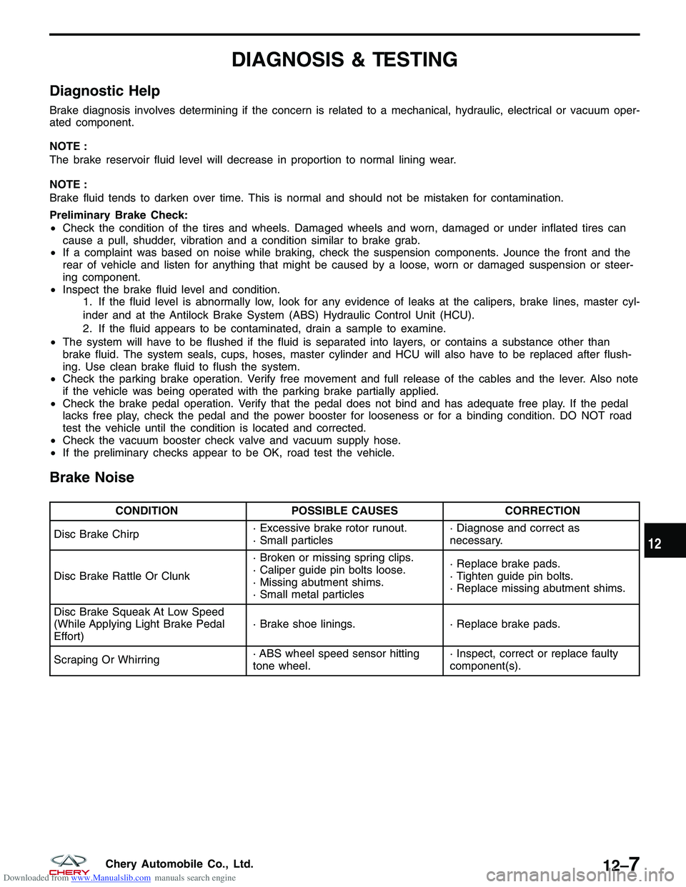
CONDITION POSSIBLE CAUSES CORRECTION
Disc Brake Chirp · Excessive brake rotor runout.
· Small particles· Diagnose and correct as
necessary.
Disc Brake Rattle Or Clunk · Broken or missing spring clips.
· Caliper guide pin bolts loose.
· Missing abutment shims.
· Small metal particles· Replace brake pads.
· Tighten guide pin bolts.
· Replace missing abutment shims.
Disc Brake Squeak At Low Speed
(While Applying Light Brake Pedal
Effort) · Brake shoe linings.
· Replace brake pads.
Scraping Or Whirring · ABS wheel speed sensor hitting
tone wheel.· Inspect, correct or replace faulty
component(s).
12
12–7Chery Automobile Co., Ltd.
Page 1429 of 1903

Downloaded from www.Manualslib.com manuals search engine ANTILOCK BRAKES
GENERAL INFORMATION12-35
Description 12-35
Operation 12-36
Specifications 12-36
Special Tools 12-37
Electrical Schematics 12-38
Antilock Brake System (ABS) Module
Connector Pin-Out Table 12-44
DIAGNOSIS & TESTING12-45
Diagnostic Help 12-45
Diagnostic Help 12-45
Ground Inspection 12-45
Diagnostic Tools 12-46
Diagnostic Trouble Code (DTC) List 12-46
Antilock Brake System DTC List 12-46
Diagnostic Trouble Code (DTC) Tests 12-47
C1101 - Battery Voltage High, C1102 -
Battery Voltage Low 12-47
C1200 - Left Front Wheel Speed
Sensor Circuit Open or Shorted 12-54
C1203 - Right Front Wheel Speed
Sensor Circuit Open or Shorted 12-59 C1206 - Left Rear Wheel Speed Sensor
Circuit Open or Shorted 12-64
C1209 - Right Rear Wheel Speed
Sensor Circuit Open or Shorted 12-69
C1604 - ECU Defect, Internal Errors or
Solenoid Fault 12-74
ON-VEHICLE SERVICE12-76
Antilock Brake System (ABS) Bleeding
Procedure 12-76
ABS Bleeding Information 12-76
ABS Bleeding Instructions 12-76
Antilock Brake System (ABS) Hydraulic
Control Module 12-77
Removal & Installation 12-77
Front Wheel Speed Sensor 12-77
Removal & Installation 12-77
Rear Wheel Speed Sensor 12-78
Removal & Installation 12-78
12–34Chery Automobile Co., Ltd.
Page 1430 of 1903
Downloaded from www.Manualslib.com manuals search engine GENERAL INFORMATION
Description
This Antilock Brake System (ABS) uses components of the base brake system, but also features the following com-
ponents:
•Hydraulic Control Unit and Antilock Brake System Module (ABS module)
• Wheel Speed Sensors (wheel speed sensor) - Four sensors (one sensor at each wheel making it a four-chan-
nel system)
The purpose of the ABS is to prevent wheel lockup under braking conditions on virtually any type of road surface.
Antilock braking is desirable because a vehicle that is stopped without locking the wheels retains directional stability
and some steering capability. This allows the driver to retain greater control of the vehicle during braking.LTSM120040
12
12–35Chery Automobile Co., Ltd.
Page 1431 of 1903

Downloaded from www.Manualslib.com manuals search engine Operation
ABS Braking
•ABS operation is available at all vehicle speeds above 20 km/h. If a wheel locking tendency is detected during
a brake application, the brake system enters the ABS mode. During ABS braking, hydraulic pressure in the four
wheel circuits is modulated to prevent any wheel from locking. Each wheel circuit is designed with a set of
electric solenoids to allow modulation. The system can build and release pressure at each wheel, depending on
signals generated by the wheel speed sensors at each wheel and received at the ABS Module.
• There are a few performance characteristics of the ABS that may at first seem abnormal, but in fact are nor-
mal. These characteristics are described below.
� If the electrical system malfunctions, the Fail-Safe function is activated, the ABS becomes inoperative and
the ABS warning lamp turns on.
� During ABS operation, the brake pedal may vibrate lightly and a mechanical noise may be heard. This is normal.
� Stopping distance may be longer than that of vehicles without ABS when vehicle drives on rough, gravel, or snow-covered (fresh, deep snow) roads.
Specifications
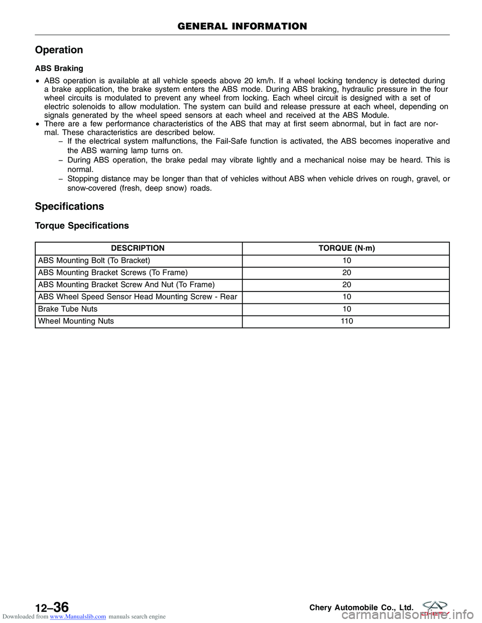
Torque Specifications
DESCRIPTION TORQUE (N·m)
ABS Mounting Bolt (To Bracket) 10
ABS Mounting Bracket Screws (To Frame) 20
ABS Mounting Bracket Screw And Nut (To Frame) 20
ABS Wheel Speed Sensor Head Mounting Screw - Rear 10
Brake Tube Nuts 10
Wheel Mounting Nuts 110
GENERAL INFORMATION
12–36Chery Automobile Co., Ltd.