Page 1369 of 1903
Downloaded from www.Manualslib.com manuals search engine Steering Wheel Return to Center Inspection
NOTE :
This test should be performed during a road test.
•Make smooth turns and sharp turns. Check the driving �sense�to ensure there is no difference between the left
and right turns in terms of steering force and the steering wheel returning to center.
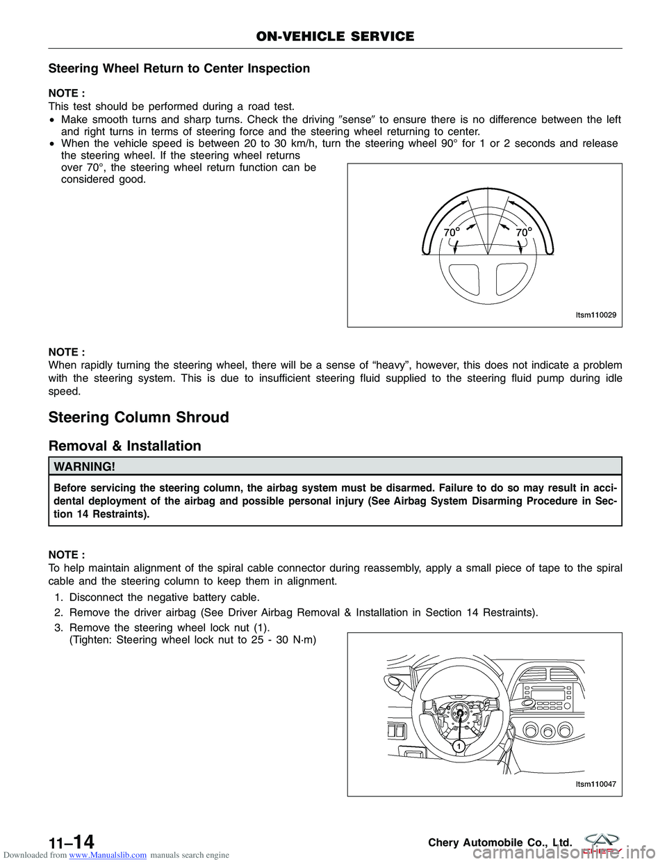
• When the vehicle speed is between 20 to 30 km/h, turn the steering wheel 90° for 1 or 2 seconds and release
the steering wheel. If the steering wheel returns
over 70°, the steering wheel return function can be
considered good.
NOTE :
When rapidly turning the steering wheel, there will be a sense of “heavy”, however, this does not indicate a problem
with the steering system. This is due to insufficient steering fluid supplied to the steering fluid pump during idle
speed.
Steering Column Shroud
Removal & Installation
WARNING!
Before servicing the steering column, the airbag system must be disarmed. Failure to do so may result in acci-
dental deployment of the airbag and possible personal injury (See Airbag System Disarming Procedure in Sec-
tion 14 Restraints).
NOTE :
To help maintain alignment of the spiral cable connector during reassembly, apply a small piece of tape to the spiral
cable and the steering column to keep them in alignment. 1. Disconnect the negative battery cable.
2. Remove the driver airbag (See Driver Airbag Removal & Installation in Section 14 Restraints).
3. Remove the steering wheel lock nut (1). (Tighten: Steering wheel lock nut to 25 - 30 N·m)
ON-VEHICLE SERVICE
LTSM110029
LTSM110047
11 –14Chery Automobile Co., Ltd.
Page 1370 of 1903
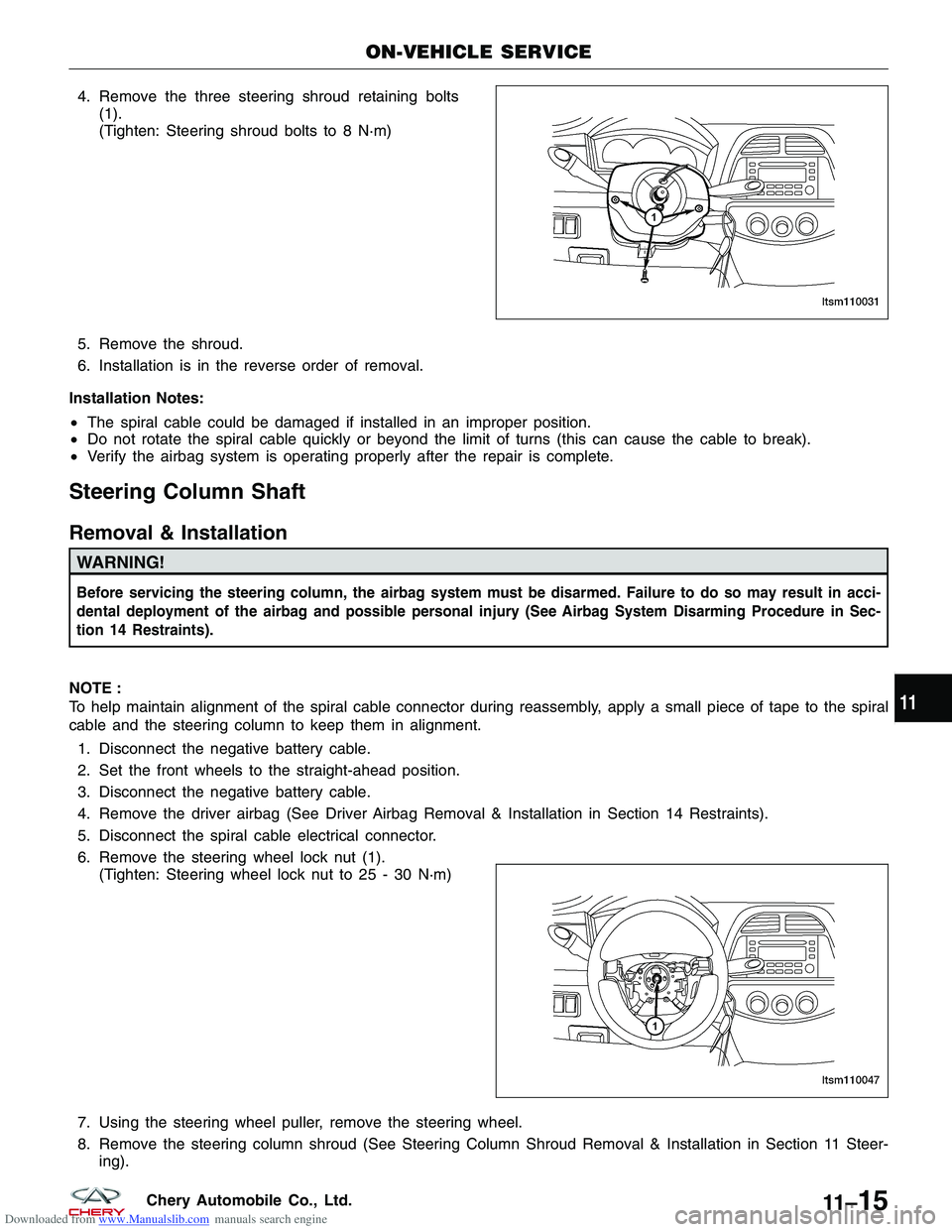
Downloaded from www.Manualslib.com manuals search engine 4. Remove the three steering shroud retaining bolts(1).
(Tighten: Steering shroud bolts to 8 N·m)
5. Remove the shroud.
6. Installation is in the reverse order of removal.
Installation Notes:
• The spiral cable could be damaged if installed in an improper position.
• Do not rotate the spiral cable quickly or beyond the limit of turns (this can cause the cable to break).
• Verify the airbag system is operating properly after the repair is complete.
Steering Column Shaft
Removal & Installation
WARNING!
Before servicing the steering column, the airbag system must be disarmed. Failure to do so may result in acci-
dental deployment of the airbag and possible personal injury (See Airbag System Disarming Procedure in Sec-
tion 14 Restraints).
NOTE :
To help maintain alignment of the spiral cable connector during reassembly, apply a small piece of tape to the spiral
cable and the steering column to keep them in alignment.
1. Disconnect the negative battery cable.
2. Set the front wheels to the straight-ahead position.
3. Disconnect the negative battery cable.
4. Remove the driver airbag (See Driver Airbag Removal & Installation in Section 14 Restraints).
5. Disconnect the spiral cable electrical connector.
6. Remove the steering wheel lock nut (1). (Tighten: Steering wheel lock nut to 25 - 30 N·m)
7. Using the steering wheel puller, remove the steering wheel.
8. Remove the steering column shroud (See Steering Column Shroud Removal & Installation in Section 11 Steer- ing).
ON-VEHICLE SERVICE
LTSM110031
LTSM110047
11
11 –15Chery Automobile Co., Ltd.
Page 1374 of 1903
Downloaded from www.Manualslib.com manuals search engine GENERAL INFORMATION
Description
The steering gear used is the rack-and-pinion type with power assist. It is mounted on the front suspension sub-
frame. The outer ends of the outer tie rods attach to the front knuckles.
NOTE :
The power steering gear should not be serviced or adjusted. If a malfunction or steering fluid leak occurs with the
steering gear, the complete steering gear needs to be replaced.
Operation
The steering wheel turns the pinion. The rack is a long flat bar with geared teeth on one side. The rack teeth mesh
with the teeth on the pinion gear. Rotation of the pinion moves the rack from left to right and right to left. The tie rod
then causes the wheels to turn to the left or right.
Specifications
Torque Specifications
DESCRIPTIONTORQUE (N·m)
Inlet / Outlet Pipe Nut 25 - 30
Intermediate Shaft Bolt 25 - 30
Steering Gear to Sub-Frame Bolts 70 - 80
Sub-Frame Assembly Bolts 180 ± 15
Tie Rod End Nut 32 - 38
Tie Rod Jam Nut 15
Wheel Mounting Nuts 110
Special Tool
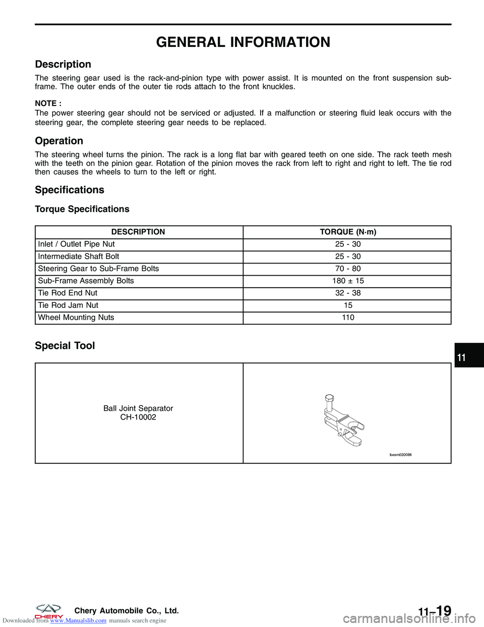
Ball Joint Separator
CH-10002
11
11 –19Chery Automobile Co., Ltd.
Page 1375 of 1903
Downloaded from www.Manualslib.com manuals search engine DIAGNOSIS & TESTING
Binding and Sticking Troubleshooting Chart
CONDITIONPOSSIBLE CAUSES CORRECTION
Difficult To Turn Wheel Sticks Or
Binds · Low fluid level.
· Tire pressure.
· Steering component.
· Loose belt.
· Low pump pressure.
· Column shaft coupler binding.
· Steering gear worn or out of
adjustment.
· Ball joints binding.
· Belt routing.· Fill to proper level.
· Adjust tire pressure.
· Inspect and lubricate.
· Adjust or replace.
· Pressure test and replace if
necessary.
· Replace coupler.
· Repair or replace gear.
· Inspect and repair if necessary.
· Verify belt routing is correct.
Insufficient Assist / Poor Return To Center Troubleshooting Chart
CONDITION
POSSIBLE CAUSES CORRECTION
Hard Turning Or Momentary
Increase In Turning Effort · Tire pressure.
· Low fluid level.
· Loose belt.
· Lack of lubrication.
· Low pump pressure or flow.
· Internal gear leak.
· Belt routing.· Adjust tire pressure.
· Fill to proper level.
· Adjust or replace.
· Inspect and lubricate steering and
suspension components.
· Pressure and flow test and repair if
necessary.
· Pressure and flow test, and repair
if necessary.
· Verify belt routing is correct.
Steering Wheel Does Not Want To
Return To Center Position · Tire pressure.
· Wheel alignment.
· Lack of lubrication.
· High friction in steering gear.
· Ball joints binding.· Adjust tire pressure.
· Align front wheels.
· Inspect and lubricate steering and
suspension components.
· Test and adjust if necessary.
· Inspect and repair if necessary.
11 –20Chery Automobile Co., Ltd.
Page 1376 of 1903
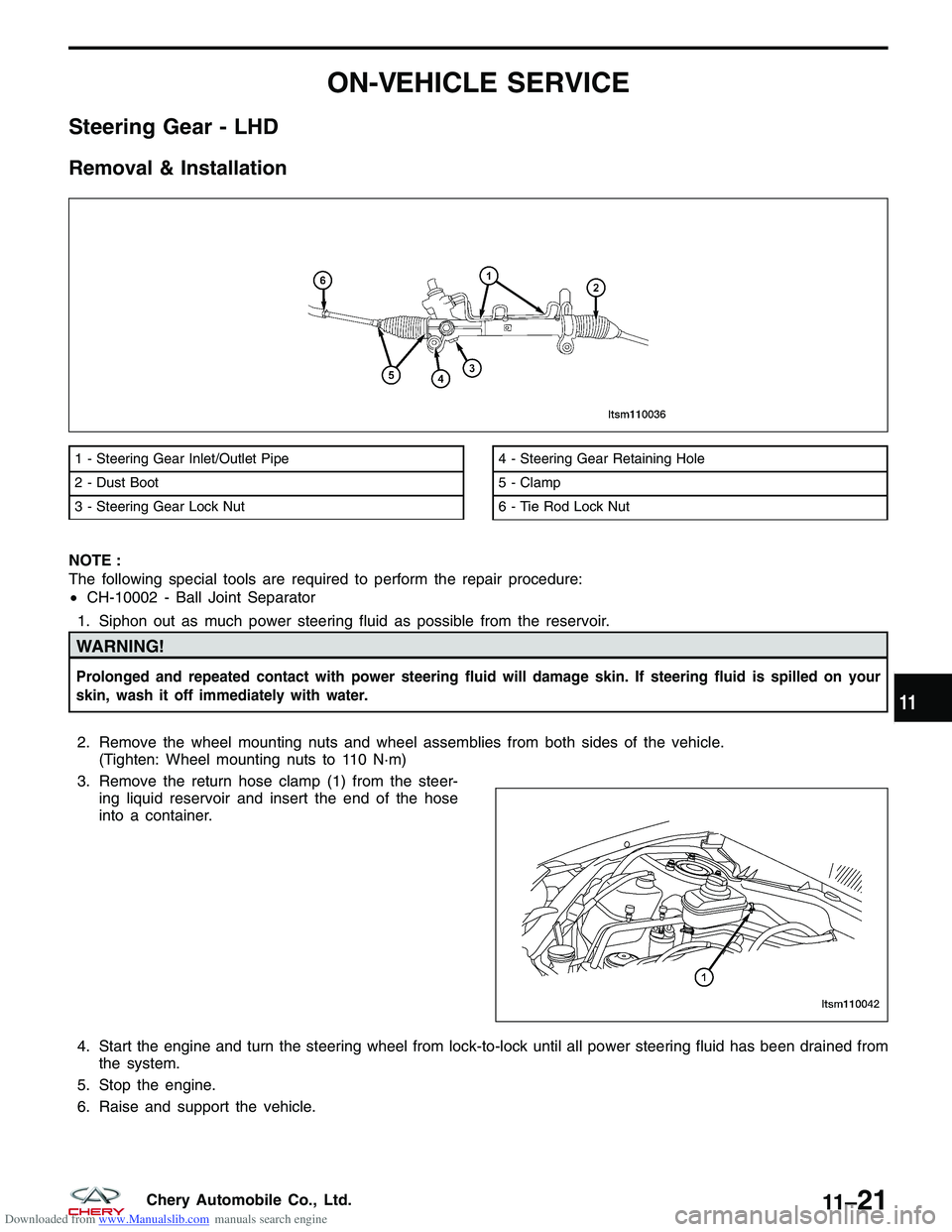
Downloaded from www.Manualslib.com manuals search engine ON-VEHICLE SERVICE
Steering Gear - LHD
Removal & Installation
NOTE :
The following special tools are required to perform the repair procedure:
•CH-10002 - Ball Joint Separator
1. Siphon out as much power steering fluid as possible from the reservoir.
WARNING!
Prolonged and repeated contact with power steering fluid will damage skin. If steering fluid is spilled on your
skin, wash it off immediately with water.
2. Remove the wheel mounting nuts and wheel assemblies from both sides of the vehicle. (Tighten: Wheel mounting nuts to 110 N·m)
3. Remove the return hose clamp (1) from the steer- ing liquid reservoir and insert the end of the hose
into a container.
4. Start the engine and turn the steering wheel from lock-to-lock until all power steering fluid has been drained from the system.
5. Stop the engine.
6. Raise and support the vehicle.
1 - Steering Gear Inlet/Outlet Pipe
2 - Dust Boot
3 - Steering Gear Lock Nut4 - Steering Gear Retaining Hole
5 - Clamp
6 - Tie Rod Lock Nut
LTSM110036
LTSM110042
11
11 –21Chery Automobile Co., Ltd.
Page 1378 of 1903
Downloaded from www.Manualslib.com manuals search engine 11. On each side of the steering gear, remove the nut(1) attaching the outer tie rod end to the steering
knuckle.
(Tighten: Outer tie rod end nut to 32 - 38 N·m)
12. Using special tool CH-10002, separate the outer tie rod ends from both steering knuckles.
13. Remove the wheel speed sensor mounting bolt (1). (Tighten: Wheel speed sensor mounting bolt to
10 ± 1 N·m)
14. Remove the wheel speed sensor and set it aside.
ON-VEHICLE SERVICE
LTSM110034
LTSM110027
LTSM100045
11
11 –23Chery Automobile Co., Ltd.
Page 1379 of 1903
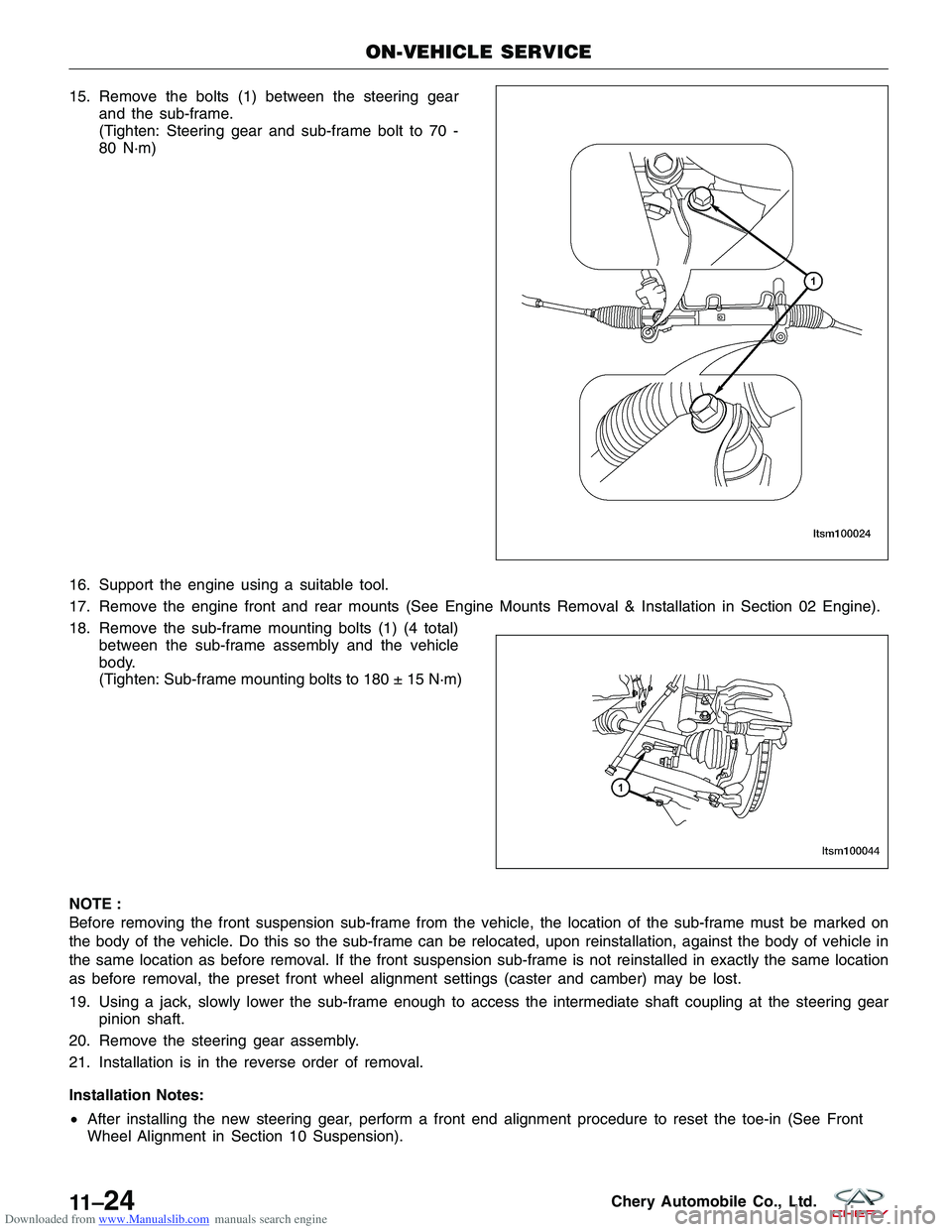
Downloaded from www.Manualslib.com manuals search engine 15. Remove the bolts (1) between the steering gearand the sub-frame.
(Tighten: Steering gear and sub-frame bolt to 70 -
80 N·m)
16. Support the engine using a suitable tool.
17. Remove the engine front and rear mounts (See Engine Mounts Removal & Installation in Section 02 Engine).
18. Remove the sub-frame mounting bolts (1) (4 total) between the sub-frame assembly and the vehicle
body.
(Tighten: Sub-frame mounting bolts to 180 ± 15 N·m)
180 ± 15 N·m)
NOTE :
Before removing the front suspension sub-frame from the vehicle, the location of the sub-frame must be marked on
the body of the vehicle. Do this so the sub-frame can be relocated, upon reinstallation, against the body of vehicle in
the same location as before removal. If the front suspension sub-frame is not reinstalled in exactly the same location
as before removal, the preset front wheel alignment settings (caster and camber) may be lost.
19. Using a jack, slowly lower the sub-frame enough to access the intermediate shaft coupling at the steering gear pinion shaft.
20. Remove the steering gear assembly.
21. Installation is in the reverse order of removal.
Installation Notes:
• After installing the new steering gear, perform a front end alignment procedure to reset the toe-in (See Front
Wheel Alignment in Section 10 Suspension).
ON-VEHICLE SERVICE
LTSM100024
LTSM100044
11 –24Chery Automobile Co., Ltd.
Page 1380 of 1903
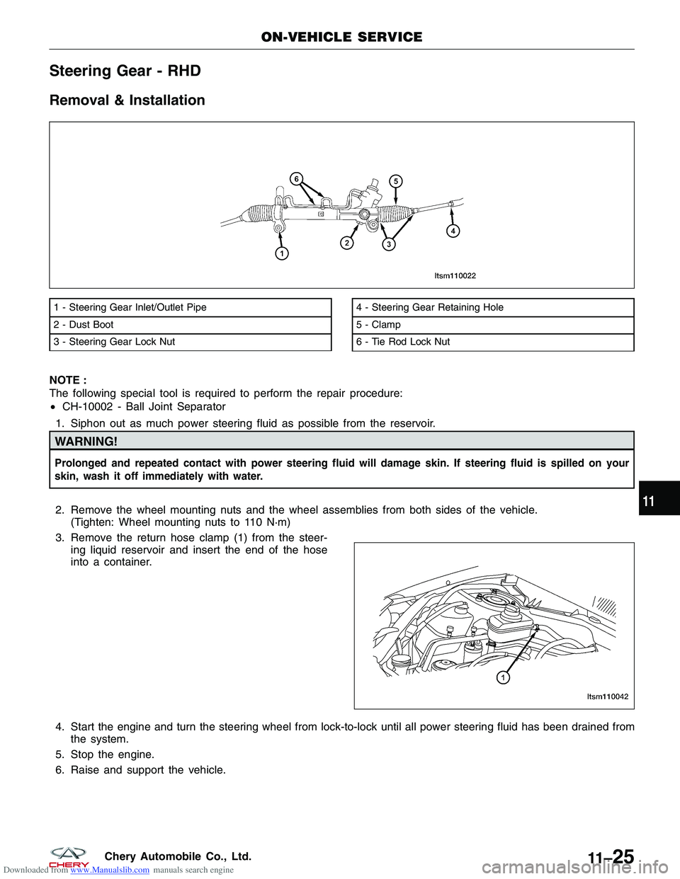
Downloaded from www.Manualslib.com manuals search engine Steering Gear - RHD
Removal & Installation
NOTE :
The following special tool is required to perform the repair procedure:
•CH-10002 - Ball Joint Separator
1. Siphon out as much power steering fluid as possible from the reservoir.
WARNING!
Prolonged and repeated contact with power steering fluid will damage skin. If steering fluid is spilled on your
skin, wash it off immediately with water.
2. Remove the wheel mounting nuts and the wheel assemblies from both sides of the vehicle. (Tighten: Wheel mounting nuts to 110 N·m)
3. Remove the return hose clamp (1) from the steer- ing liquid reservoir and insert the end of the hose
into a container.
4. Start the engine and turn the steering wheel from lock-to-lock until all power steering fluid has been drained from the system.
5. Stop the engine.
6. Raise and support the vehicle.
1 - Steering Gear Inlet/Outlet Pipe
2 - Dust Boot
3 - Steering Gear Lock Nut4 - Steering Gear Retaining Hole
5 - Clamp
6 - Tie Rod Lock Nut
ON-VEHICLE SERVICE
LTSM110022
LTSM110042
11
11 –25Chery Automobile Co., Ltd.