Page 1308 of 1903

Downloaded from www.Manualslib.com manuals search engine ON-VEHICLE SERVICE
Front Steering Knuckle
Description
The steering knuckle is a single casting with legs machined for attachment to the front strut assembly on the top and
steering linkage on the trailing leading end. The steering knuckle also has two machined, drilled legs on the end
casting to support and align the front disc brake caliper adapter.
Operation
The steering knuckle supports the hub and bearing. The front suspension steering knuckle is not a repairable com-
ponent of the front suspension. It must be replaced if damaged in any way. If it is determined that the steering
knuckle is bent when servicing the vehicle, no attempt should be made to straighten the steering knuckle.
Removal & Installation
NOTE :
The following special tools are required to perform the repair procedure:
•CH-10002 - Ball Joint Separator
1. Raise and support the vehicle.
2. Remove the wheel mounting nuts and the wheel assembly. (Tighten: Wheel mounting nuts to 110 N·m)
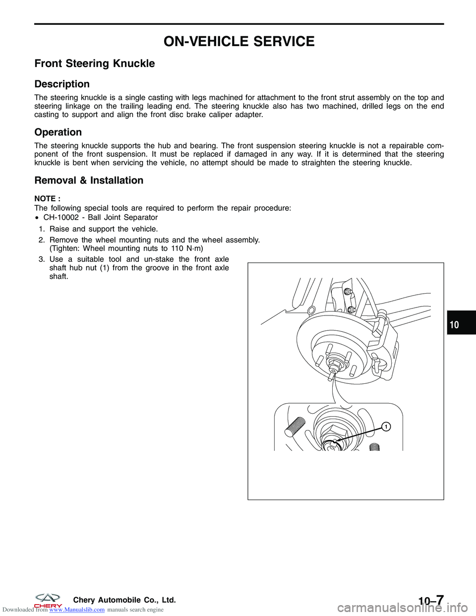
3. Use a suitable tool and un-stake the front axle shaft hub nut (1) from the groove in the front axle
shaft.
??????
10
10–7Chery Automobile Co., Ltd.
Page 1309 of 1903
Downloaded from www.Manualslib.com manuals search engine 4. While a helper applies the brakes to keep the hubfrom rotating, remove the front axle shaft nut (1).
(Tighten: Front axle shaft nut to 135 N·m)
5. Access and remove the front brake rotor (See Front Brake Rotor Remove & Installation in Section 12 Brakes).
6. Remove the wheel speed sensor mounting bolt (1). (Tighten: Wheel speed sensor mounting bolt to 10
± 1 N·m)
7. Remove the wheel speed sensor and set it aside.
8. Remove the lower ball joint mounting nut (1) attaching the lower control arm to the knuckle.
(Tighten: Control arm to steering knuckle nut to
120 ± 10 N·m)
9. Remove the nut (1) attaching the outer tie rod end to the steering knuckle.
(Tighten: Outer tie rod end nut to 32 - 38 N·m)
ON-VEHICLE SERVICE
LTSM090006
LTSM100045
LTSM100006
LTSM110034
10–8Chery Automobile Co., Ltd.
Page 1310 of 1903

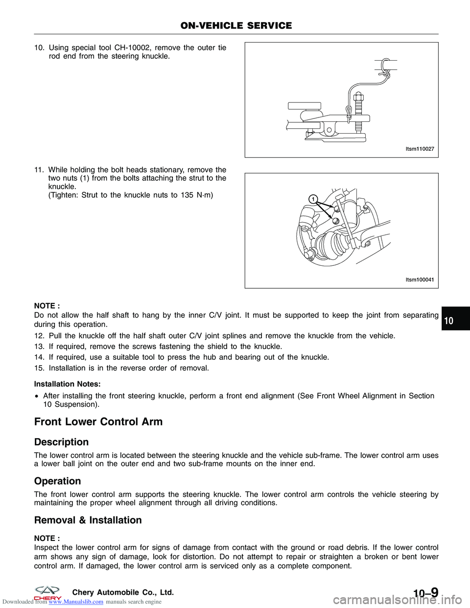
Downloaded from www.Manualslib.com manuals search engine 10. Using special tool CH-10002, remove the outer tierod end from the steering knuckle.
11. While holding the bolt heads stationary, remove the two nuts (1) from the bolts attaching the strut to the
knuckle.
(Tighten: Strut to the knuckle nuts to 135 N·m)
NOTE :
Do not allow the half shaft to hang by the inner C/V joint. It must be supported to keep the joint from separating
during this operation.
12. Pull the knuckle off the half shaft outer C/V joint splines and remove the knuckle from the vehicle.
13. If required, remove the screws fastening the shield to the knuckle.
14. If required, use a suitable tool to press the hub and bearing out of the knuckle.
15. Installation is in the reverse order of removal.
Installation Notes:
• After installing the front steering knuckle, perform a front end alignment (See Front Wheel Alignment in Section
10 Suspension).
Front Lower Control Arm
Description
The lower control arm is located between the steering knuckle and the vehicle sub-frame. The lower control arm uses
a lower ball joint on the outer end and two sub-frame mounts on the inner end.
Operation
The front lower control arm supports the steering knuckle. The lower control arm controls the vehicle steering by
maintaining the proper wheel alignment through all driving conditions.
Removal & Installation
NOTE :
Inspect the lower control arm for signs of damage from contact with the ground or road debris. If the lower control
arm shows any sign of damage, look for distortion. Do not attempt to repair or straighten a broken or bent lower
control arm. If damaged, the lower control arm is serviced only as a complete component.
ON-VEHICLE SERVICE
LTSM110027
LTSM100041
10
10–9Chery Automobile Co., Ltd.
Page 1311 of 1903
Downloaded from www.Manualslib.com manuals search engine 1. Raise and support the vehicle.
2. Remove the wheel mounting nuts and the wheel assembly.(Tighten: Wheel mounting nuts to 110 N·m)
3. Remove the bolt (1) between the control arm and the sub-frame.
(Tighten: Control arm to sub-frame bolt to
180 ± 10 N·m)
4. Remove the nut (1) between the control arm and the steering knuckle.
(Tighten: Control arm to steering knuckle nut to
120 ± 10 N·m)
5. Remove the bolt (1) between the rear rubber sleeve of the control arm and the sub-frame.
(Tighten: Rear rubber sleeve control arm to sub-
frame bolt to 180 ± 10 N·m)
6. Remove the control arm from the vehicle.
7. Perform the following inspection procedure before installation.
ON-VEHICLE SERVICE
LTSM100055
LTSM100006
LTSM100057
10–10Chery Automobile Co., Ltd.
Page 1316 of 1903
Downloaded from www.Manualslib.com manuals search engine 7. Remove the two bolts (1) between the front strutand the steering knuckle.
(Tighten: Front strut to steering knuckle bolts to
120 ± 10 N·m)
8. Remove the three upper strut mounting nuts (1) from the strut tower.
(Tighten: Upper strut mounting nuts to 50 ± 10
N·m)
9. Remove the front strut assembly.
10. Installation is in the reverse order of removal.
Installation Notes:
• After installation, each bolt must be tightened to the required tightening torque.
• Four-wheel alignment inspection is required after the installation.
ON-VEHICLE SERVICE
LTSM100041
LTSM100002
10
10–15Chery Automobile Co., Ltd.
Page 1318 of 1903

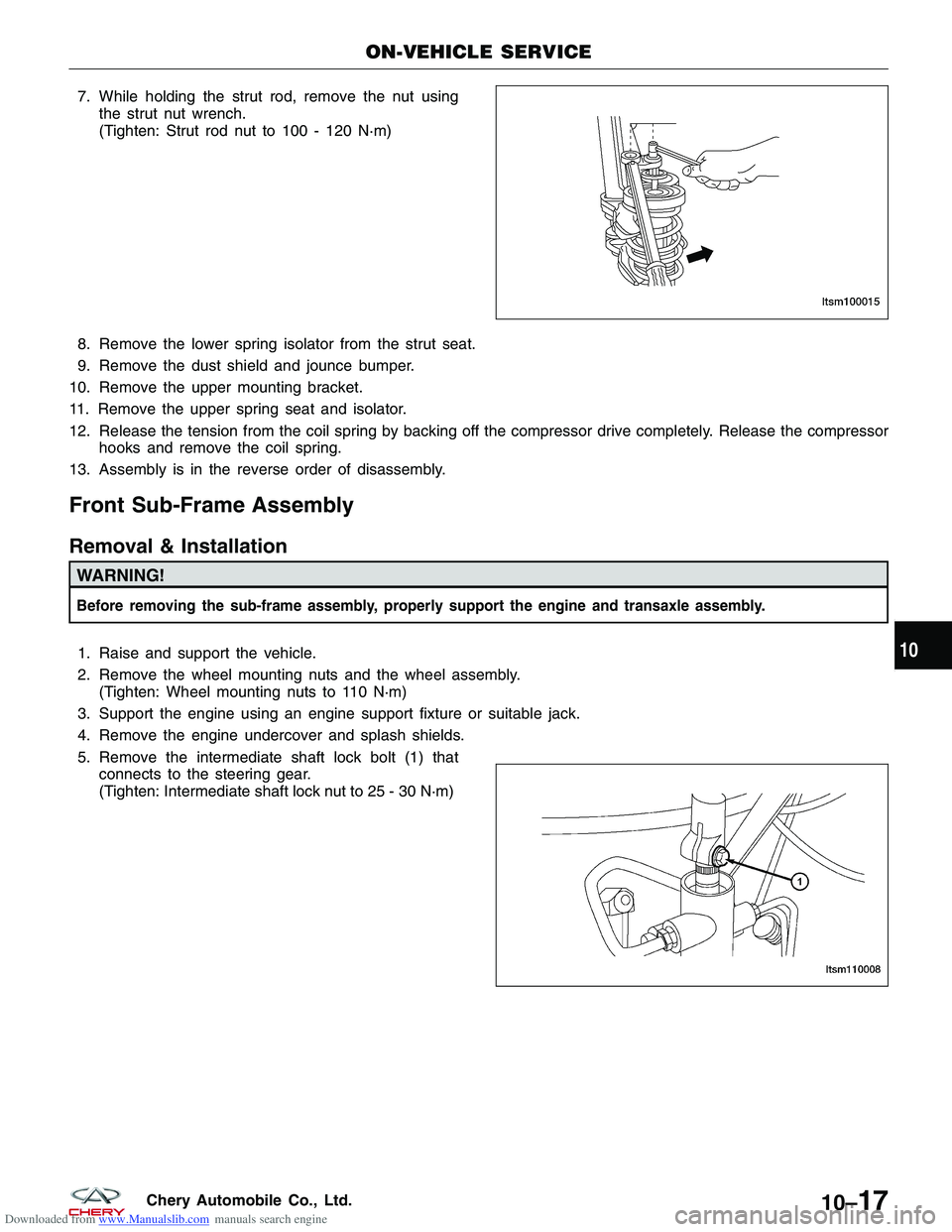
Downloaded from www.Manualslib.com manuals search engine 7. While holding the strut rod, remove the nut usingthe strut nut wrench.
(Tighten: Strut rod nut to 100 - 120 N·m)
8. Remove the lower spring isolator from the strut seat.
9. Remove the dust shield and jounce bumper.
10. Remove the upper mounting bracket.
11. Remove the upper spring seat and isolator.
12. Release the tension from the coil spring by backing off the compressor drive completely. Release the compressor hooks and remove the coil spring.
13. Assembly is in the reverse order of disassembly.
Front Sub-Frame Assembly
Removal & Installation
WARNING!
Before removing the sub-frame assembly, properly support the engine and transaxle assembly.
1. Raise and support the vehicle.
2. Remove the wheel mounting nuts and the wheel assembly. (Tighten: Wheel mounting nuts to 110 N·m)
3. Support the engine using an engine support fixture or suitable jack.
4. Remove the engine undercover and splash shields.
5. Remove the intermediate shaft lock bolt (1) that connects to the steering gear.
(Tighten: Intermediate shaft lock nut to 25 - 30 N·m)
ON-VEHICLE SERVICE
LTSM100015
LTSM110008
10
10–17Chery Automobile Co., Ltd.
Page 1319 of 1903
Downloaded from www.Manualslib.com manuals search engine 6. Remove the nut (1) between the control arm andthe steering knuckle.
(Tighten: Control arm to steering knuckle nut to
120 ± 10 N·m)
7. Remove the wheel speed sensor mounting bolt (1). (Tighten: Wheel speed sensor mounting bolt to 10
± 1 N·m)
8. Remove the wheel speed sensor and set it aside.
9. Remove the left and right front stabilizer bar links (See Front Stabilizer Bar Link Removal & Installation in Sec- tion 10 Suspension).
10. Remove the nut (1) attaching the outer tie rod ends to the steering knuckle on each side of the steering
rack.
(Tighten: Outer tie rod end nut to 35 N·m)
11. Remove the exhaust pipe assembly mounting bolts (1).
(Tighten: Exhaust pipe assembly mounting bolts to
25 ± 3 N·m)
ON-VEHICLE SERVICE
LTSM100006
LTSM100045
LTSM110034 VISM110016
10–18Chery Automobile Co., Ltd.
Page 1340 of 1903

Downloaded from www.Manualslib.com manuals search engine GENERAL INFORMATION
Description
Vehicle wheel alignment is the positioning of all interrelated front and rear suspension angles. These angles affect the
handling and steering of the vehicle when it is in motion. Proper wheel alignment is essential for efficient steering,
good directional stability, and proper tire wear.
The method of checking a vehicle’s front and rear wheel alignment varies depending on the manufacturer and type
of equipment used. The manufacturer’s instructions should always be followed to ensure accuracy of the alignment.
On this vehicle, the suspension angles that can be adjusted are as follows:
Front Axle
•Camber
• Caster
• Toe-in
Rear Axle
• Camber
• Toe-in
Check the wheel alignment and make all wheel alignment adjustments with the vehicle standing at its proper curb
height specification. Curb height is the normal riding height of the vehicle. It is measured from a certain point on the
vehicle to the ground or a designated area while the vehicle is sitting on a flat, level surface.
Operation
Curb Height Measurement
The wheel alignment is to be checked and all alignment adjustments made with the vehicle at its required curb height
specification.
• Vehicle height is to be checked with the vehicle on a flat, level surface, preferably a vehicle alignment rack.
• The tires are to be inflated to the recommended pressure.
• All tires are to be the same size as standard equipment.
• Vehicle height is checked with the fuel tank full of fuel, and no passenger or luggage compartment load.
• Vehicle height is not adjustable.
• If the measurement is not within specifications, inspect the vehicle for bent or weak suspension components.
• Compare the parts tag on the suspect coil spring(s) to the parts book and the vehicle sales code, checking for
a match.
• Once removed from the vehicle, compare the coil spring height to a new or known good coil spring. The
heights should vary if the suspect spring is weak.
NOTE :
Prior to reading the curb height measurement, the front and rear of the vehicle must be jounced to settle the sus-
pension. Induce jounce by pushing down on the center of the bumper (fascia), using care not to damage the vehicle,
moving the vehicle up and down, gradually increasing the suspension travel with each stroke. Release the bumper at
the bottom of each stroke, repeating this action several times. Perform this to both front and rear suspensions an
equal number of times.
Pre-Wheel Alignment Inspection
Before any attempt is made to change or correct the wheel alignment, the following inspection and necessary cor-
rections must be made to the vehicle to ensure proper alignment. 1. Verify the fuel tank is full of fuel. If the fuel tank is not full, the reduction in weight will affect the curb height of the vehicle and the alignment specifications.
2. The passenger and luggage compartments of the vehicle should be free of any load that is not factory equip- ment.
10
10–39Chery Automobile Co., Ltd.