2009 CHERY TIGGO sensor
[x] Cancel search: sensorPage 1048 of 1903
Downloaded from www.Manualslib.com manuals search engine On Board Diagnostic Logic
•Self-diagnosis detection logic.
DTC NO. DTC
DEFINITION DTC
DETECTION CONDITION DTC SET CONDITION
POSSIBLE
CAUSES
P1928 Shift lock
solenoid circuit short to power supply Ignition on or
vehicle is driving The Transaxle Control Module (TCM)
will set this DTC when the TCM
detects that the shift lever lock
solenoid circuit shorted to power
supply.•
Shift lock
solenoid valve
• Harness or
connectors (The
sensor circuit is
shorted)
• Transaxle
Control Module
(TCM)
DTC Confirmation Procedure:
Before performing the following procedure, confirm that battery voltage is more than 12 V.
• Connect the X-431 scan tool to the Data Link Connector (DLC) - use the most current software available.
• Turn ignition switch on, with the scan tool, view and erase stored DTCs in the TCM.
• Start the engine and warm it to normal operating temperature.
• Try to operate the shifter selector.
• With the scan tool, select view DTC and data stream.
• If the DTC is detected, the DTC condition is current. Go to Diagnostic Procedure - Step 1.
• If the DTC is not detected, the DTC condition is intermittent (See Diagnostic Help and Intermittent DTC Trou-
bleshooting in Section 08 Transaxle & Transfer Case for more information).
• If using the appropriate diagnostic test tool, you can diagnose the TCM harness while the TCM is still con-
nected.
• Using the appropriate diagnostic test tool in this way will help prevent electrical connector terminal damage.
NOTE :
While performing electrical diagnosis & testing, always refer to the electrical schematics for specific circuit
and component information.
Diagnostic Procedure
1.CHECK SHIFT LOCK SOLENOID VALVE SIGNAL
• With the scan tool, select view DTC and data stream.
• Start the engine.
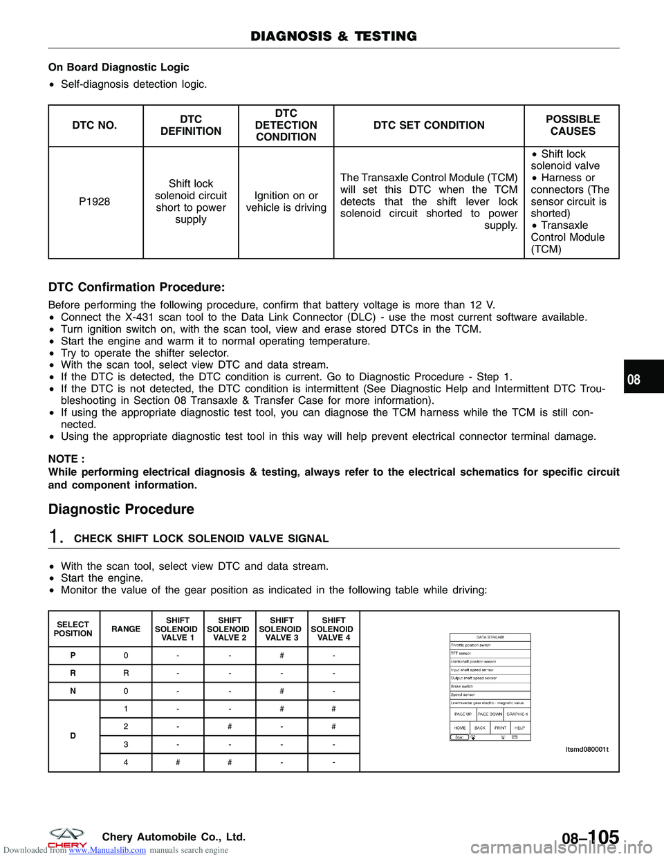
• Monitor the value of the gear position as indicated in the following table while driving:
SELECT
POSITION RANGESHIFT
SOLENOID VA LV E 1 SHIFT
SOLENOID VA LV E 2 SHIFT
SOLENOID VA LV E 3 SHIFT
SOLENOID VA LV E 4
P 0- -#-
R R----
N 0- -#-
D 1- -##
2-#-#
3----
4## -
-
DIAGNOSIS & TESTING
08
08–105Chery Automobile Co., Ltd.
Page 1053 of 1903
Downloaded from www.Manualslib.com manuals search engine On Board Diagnostic Logic
•Self-diagnosis detection logic.
DTC NO. DTC
DEFINITION DTC
DETECTION CONDITION DTC SET CONDITION
POSSIBLE
CAUSES
P1928 Shift lock
solenoid valve open circuit or
short to ground Ignition switch
on or vehicle is driving The Transaxle Control Module
(TCM) will set this DTC when the
TCM detects that the shift lever lock
solenoid circuit shorted to ground or
open. •
Shift lock
solenoid valve
• Harness or
connectors (The
sensor circuit is
open or shorted)
• Transaxle
Control Module
(TCM)
DTC Confirmation Procedure:
Before performing the following procedure, confirm that battery voltage is more than 12 V.
• Connect the X-431 scan tool to the Data Link Connector (DLC) - use the most current software available.
• Turn ignition switch on, with the scan tool, view and erase stored DTCs in the TCM.
• Start the engine and warm it to normal operating temperature.
• Try to operate the shifter selector.
• With the scan tool, select view DTC and data stream.
• If the DTC is detected, the DTC condition is current. Go to Diagnostic Procedure - Step 1.
• If the DTC is not detected, the DTC condition is intermittent (See Diagnostic Help and Intermittent DTC Trou-
bleshooting in Section 08 Transaxle & Transfer Case for more information).
• If using the appropriate diagnostic test tool, you can diagnose the TCM harness while the TCM is still con-
nected.
• Using the appropriate diagnostic test tool in this way will help prevent electrical connector terminal damage.
NOTE :
While performing electrical diagnosis & testing, always refer to the electrical schematics for specific circuit
and component information.
Diagnostic Procedure
1.CHECK SHIFT LOCK SOLENOID VALVE SIGNAL
• With the scan tool, select view DTC and data stream for A/T.
• Start the engine.
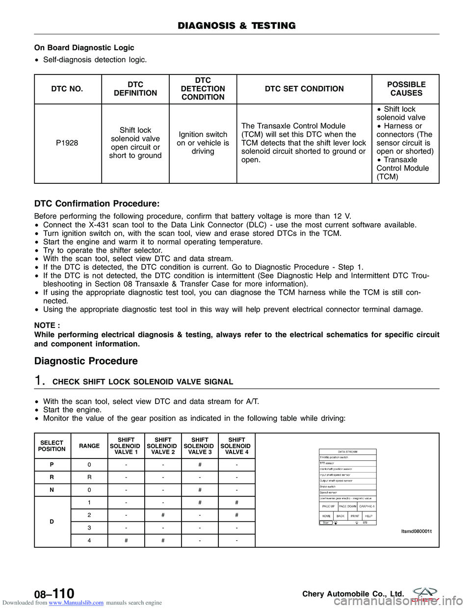
• Monitor the value of the gear position as indicated in the following table while driving:
SELECT
POSITION RANGESHIFT
SOLENOID VA LV E 1 SHIFT
SOLENOID VA LV E 2 SHIFT
SOLENOID VA LV E 3 SHIFT
SOLENOID VA LV E 4
P 0- -#-
R R----
N 0- -#-
D 1- -##
2-#-#
3----
4## -
-
DIAGNOSIS & TESTING
08–11 0Chery Automobile Co., Ltd.
Page 1058 of 1903
Downloaded from www.Manualslib.com manuals search engine On Board Diagnostic Logic
•Self-diagnosis detection logic.
DTC NO. DTC
DEFINITION DTC
DETECTION CONDITION DTC SET CONDITION
POSSIBLE
CAUSES
P2709 Shift Solenoid
Valve 6 (SSV6) short to power supply Vehicle is
driving The Transaxle Control Module
(TCM) will set this DTC when the
TCM detected an improper voltage
drop when it tries to operate the
solenoid valve. •
Shift Solenoid
Valve 6 (SSV6)
• Harness or
connectors (The
sensor circuit
short to power
supply)
• Transaxle
Control Module
(TCM)
DTC Confirmation Procedure:
Before performing the following procedure, confirm that battery voltage is more than 12 V.
• Connect the X-431 scan tool to the diagnostic connector, press the POWER key to start the X-431.
• Start the engine and warm it to normal operating temperature.
• Drive the vehicle in 1st, 2nd, 3rd and 4th gears.
• With the scan tool, select view DTC and data stream.
• If the DTC is detected, the DTC condition is current. Go to Diagnostic Procedure - Step 1.
• If the DTC is not detected, the DTC condition is intermittent (See Diagnostic Help and Intermittent DTC Trou-
bleshooting in Section 08 Transaxle & Transfer Case for more information).
• If using the appropriate diagnostic test tool, you can diagnose the TCM harness while the TCM is still con-
nected.
• Using the appropriate diagnostic test tool in this way will help prevent electrical connector terminal damage.
NOTE :
While performing electrical diagnosis & testing, always refer to the electrical schematics for specific circuit
and component information.
Diagnostic Procedure
1.CHECK A/T SOLENOID SIGNAL
• With the scan tool, select view DTC and data stream for A/T.
• Start the engine.
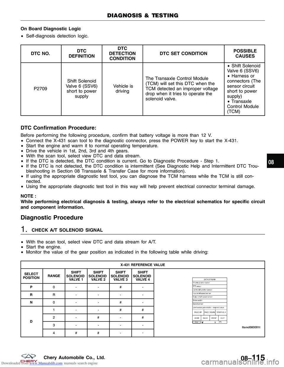
• Monitor the value of the gear position as indicated in the following table while driving:
X-431 REFERENCE VALUE
SELECT
POSITION RANGESHIFT
SOLENOID VA LV E 1 SHIFT
SOLENOID VA LV E 2 SHIFT
SOLENOID VA LV E 3 SHIFT
SOLENOID VA LV E 4
P 0- -#-
R R----
N 0- -#-
D 1- -##
2-#-#
3----
4## -
-
DIAGNOSIS & TESTING
08
08–11 5Chery Automobile Co., Ltd.
Page 1063 of 1903
Downloaded from www.Manualslib.com manuals search engine On Board Diagnostic Logic
•Self-diagnosis detection logic.
DTC NO. DTC
DEFINITION DTC
DETECTION CONDITION DTC SET CONDITION
POSSIBLE
CAUSES
P2709 Shift Solenoid
Valve 6 (SSV6)
open or short to ground circuit Vehicle is driving The Transaxle Control Module
(TCM) will set this DTC when the
TCM detected an improper voltage
drop when it tries to operate the
solenoid valve. •
Shift Solenoid
Valve 6 (SSV6)
• Harness or
connectors (The
sensor circuit is
open or shorted)
• Transaxle
Control Module
(TCM)
DTC Confirmation Procedure:
Before performing the following procedure, confirm that battery voltage is more than 12 V.
• Connect the X-431 scan tool to the Data Link Connector (DLC) - use the most current software available.
• After connection, press [POWER] key to start X-431.
• Turn ignition switch on, with the scan tool, view and erase stored DTCs in the TCM.
• Start the engine and warm it to normal operating temperature.
• Drive the vehicle in 1st, 2nd, 3rd and 4th gears.
• With the scan tool, select view DTC and data stream.
• If the DTC is detected, the DTC condition is current. Go to Diagnostic Procedure - Step 1.
• If the DTC is not detected, the DTC condition is intermittent (See Diagnostic Help and Intermittent DTC Trou-
bleshooting in Section 08 Transaxle & Transfer Case for more information).
• If using the appropriate diagnostic test tool, you can diagnose the TCM harness while the TCM is still con-
nected.
• Using the appropriate diagnostic test tool in this way will help prevent electrical connector terminal damage.
NOTE :
While performing electrical diagnosis & testing, always refer to the electrical schematics for specific circuit
and component information.
DIAGNOSIS & TESTING
08–120Chery Automobile Co., Ltd.
Page 1069 of 1903
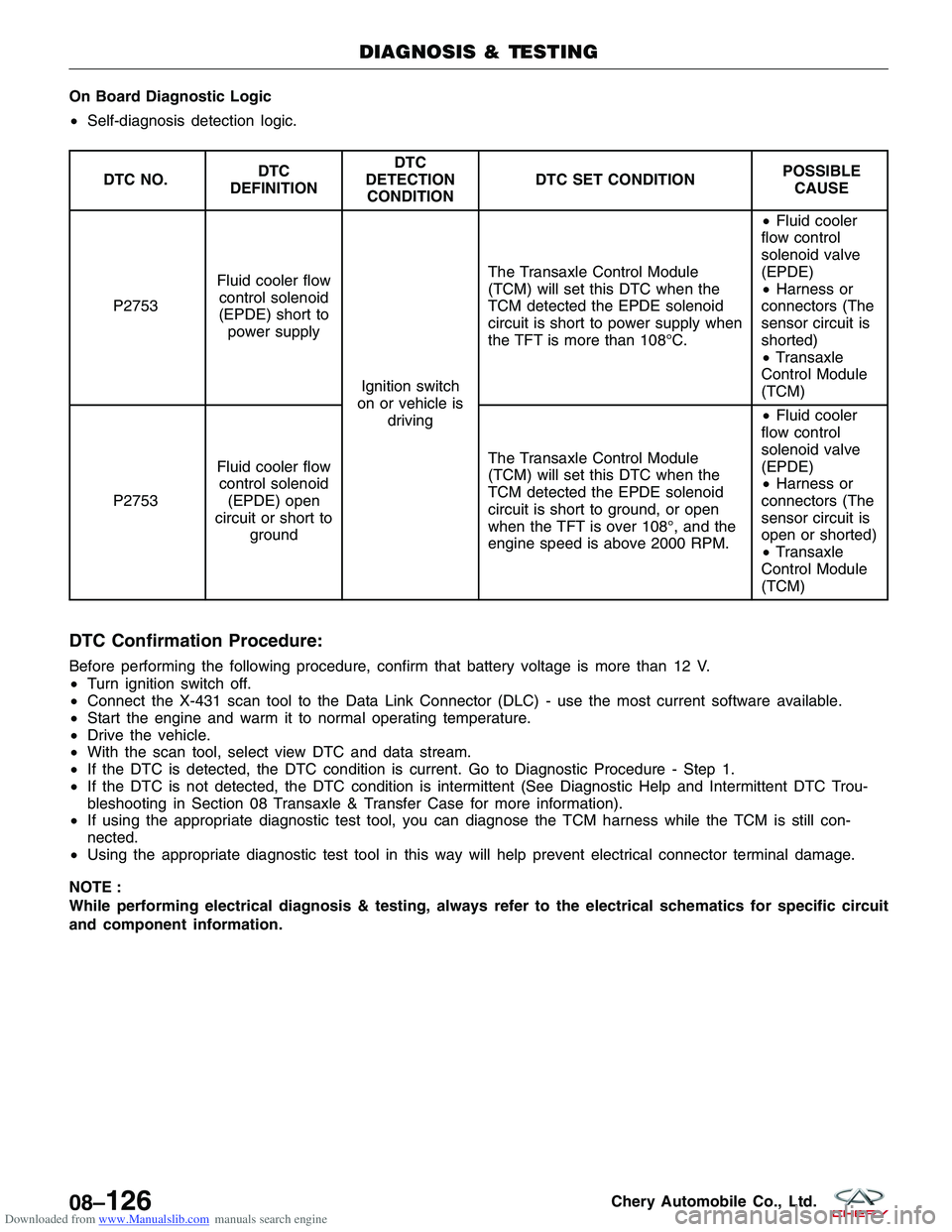
Downloaded from www.Manualslib.com manuals search engine On Board Diagnostic Logic
•Self-diagnosis detection logic.
DTC NO. DTC
DEFINITION DTC
DETECTION CONDITION DTC SET CONDITION
POSSIBLE
CAUSE
P2753 Fluid cooler flow
control solenoid
(EPDE) short to power supply
Ignition switch
on or vehicle is driving The Transaxle Control Module
(TCM) will set this DTC when the
TCM detected the EPDE solenoid
circuit is short to power supply when
the TFT is more than 108°C.
•
Fluid cooler
flow control
solenoid valve
(EPDE)
• Harness or
connectors (The
sensor circuit is
shorted)
• Transaxle
Control Module
(TCM)
P2753 Fluid cooler flow
control solenoid (EPDE) open
circuit or short to ground The Transaxle Control Module
(TCM) will set this DTC when the
TCM detected the EPDE solenoid
circuit is short to ground, or open
when the TFT is over 108°, and the
engine speed is above 2000 RPM. •
Fluid cooler
flow control
solenoid valve
(EPDE)
• Harness or
connectors (The
sensor circuit is
open or shorted)
• Transaxle
Control Module
(TCM)
DTC Confirmation Procedure:
Before performing the following procedure, confirm that battery voltage is more than 12 V.
• Turn ignition switch off.
• Connect the X-431 scan tool to the Data Link Connector (DLC) - use the most current software available.
• Start the engine and warm it to normal operating temperature.
• Drive the vehicle.
• With the scan tool, select view DTC and data stream.
• If the DTC is detected, the DTC condition is current. Go to Diagnostic Procedure - Step 1.
• If the DTC is not detected, the DTC condition is intermittent (See Diagnostic Help and Intermittent DTC Trou-
bleshooting in Section 08 Transaxle & Transfer Case for more information).
• If using the appropriate diagnostic test tool, you can diagnose the TCM harness while the TCM is still con-
nected.
• Using the appropriate diagnostic test tool in this way will help prevent electrical connector terminal damage.
NOTE :
While performing electrical diagnosis & testing, always refer to the electrical schematics for specific circuit
and component information.
DIAGNOSIS & TESTING
08–126Chery Automobile Co., Ltd.
Page 1074 of 1903
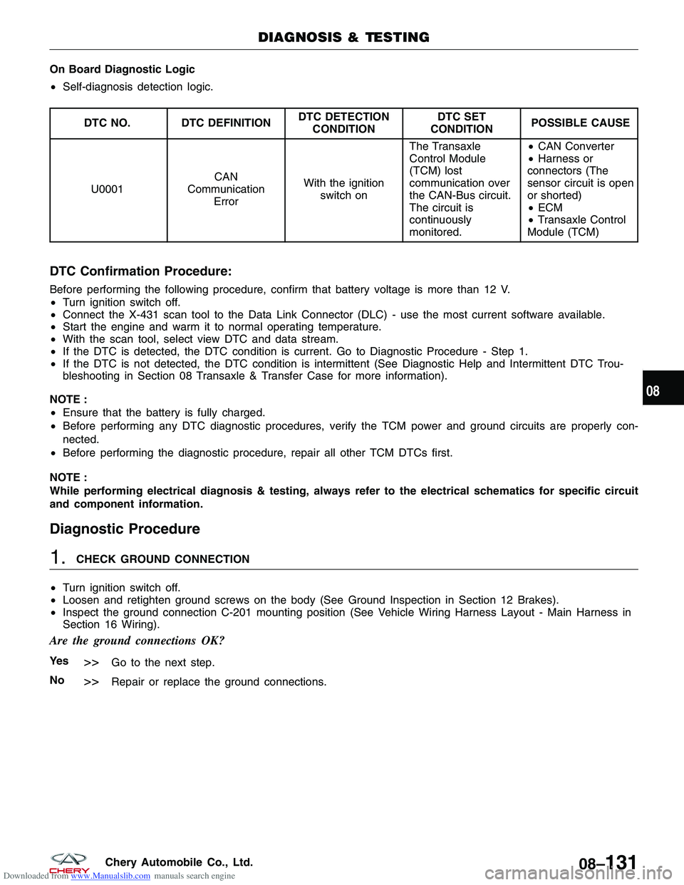
Downloaded from www.Manualslib.com manuals search engine On Board Diagnostic Logic
•Self-diagnosis detection logic.
DTC NO. DTC DEFINITION DTC DETECTION
CONDITION DTC SET
CONDITION POSSIBLE CAUSE
U0001 CAN
Communication Error With the ignition
switch on The Transaxle
Control Module
(TCM) lost
communication over
the CAN-Bus circuit.
The circuit is
continuously
monitored. •
CAN Converter
• Harness or
connectors (The
sensor circuit is open
or shorted)
• ECM
• Transaxle Control
Module (TCM)
DTC Confirmation Procedure:
Before performing the following procedure, confirm that battery voltage is more than 12 V.
• Turn ignition switch off.
• Connect the X-431 scan tool to the Data Link Connector (DLC) - use the most current software available.
• Start the engine and warm it to normal operating temperature.
• With the scan tool, select view DTC and data stream.
• If the DTC is detected, the DTC condition is current. Go to Diagnostic Procedure - Step 1.
• If the DTC is not detected, the DTC condition is intermittent (See Diagnostic Help and Intermittent DTC Trou-
bleshooting in Section 08 Transaxle & Transfer Case for more information).
NOTE :
• Ensure that the battery is fully charged.
• Before performing any DTC diagnostic procedures, verify the TCM power and ground circuits are properly con-
nected.
• Before performing the diagnostic procedure, repair all other TCM DTCs first.
NOTE :
While performing electrical diagnosis & testing, always refer to the electrical schematics for specific circuit
and component information.
Diagnostic Procedure
1.CHECK GROUND CONNECTION
• Turn ignition switch off.
• Loosen and retighten ground screws on the body (See Ground Inspection in Section 12 Brakes).
• Inspect the ground connection C-201 mounting position (See Vehicle Wiring Harness Layout - Main Harness in
Section 16 Wiring).
Are the ground connections OK?
Ye s>>Go to the next step.
No
>>Repair or replace the ground connections.
DIAGNOSIS & TESTING
08
08–131Chery Automobile Co., Ltd.
Page 1079 of 1903
Downloaded from www.Manualslib.com manuals search engine ON-VEHICLE SERVICE
DPO Automatic Transaxle Assembly
Removal & Installation
1. Raise and support the vehicle.
2. Remove the engine cover.
3. Remove the battery and battery tray (See Battery Removal & Installation in Section 05 Starting & Charging).
4. Remove the air cleaner and air duct assembly.
5. Drain the cooling system (See Cooling System Draining Procedure in Section 06 Cooling System).
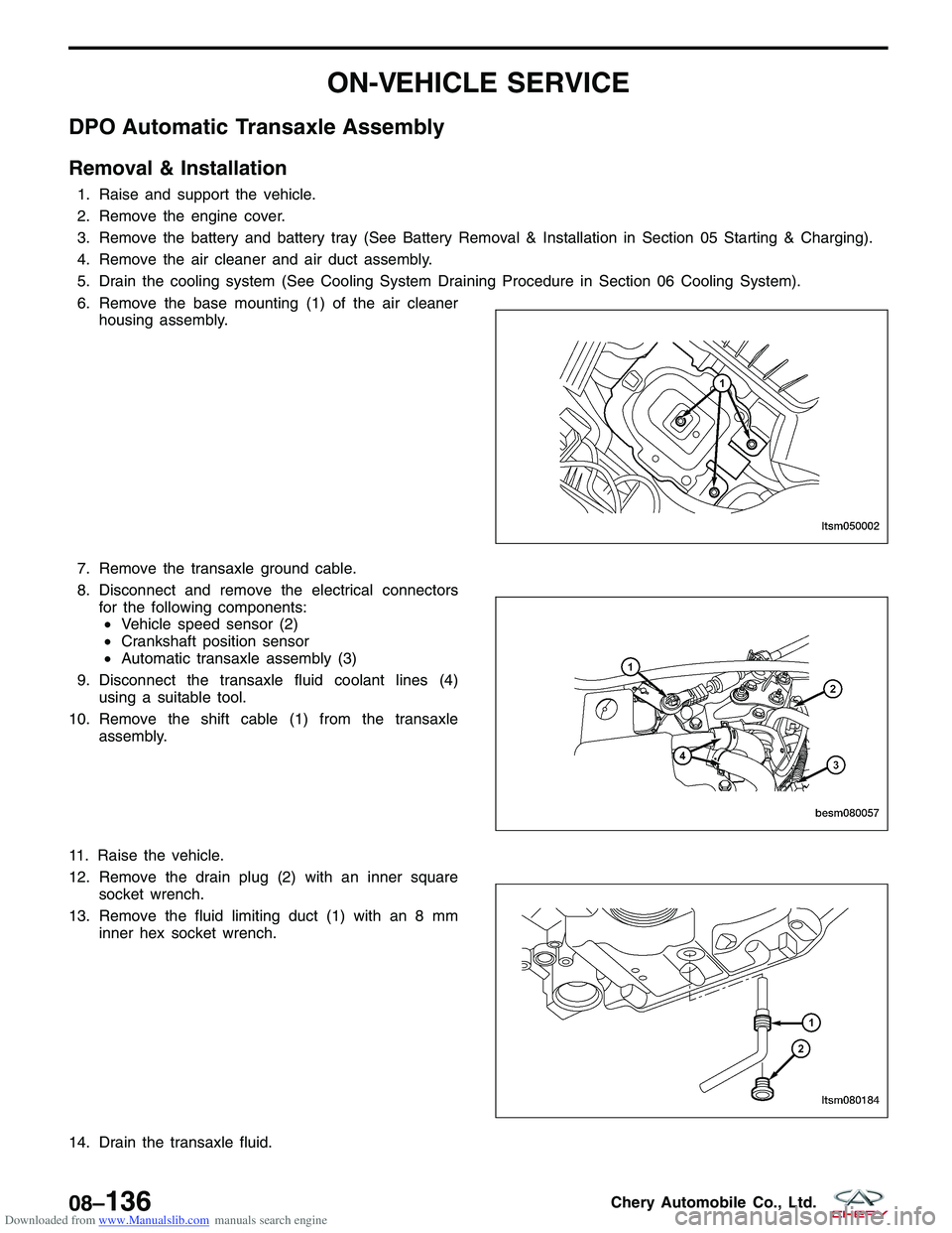
6. Remove the base mounting (1) of the air cleanerhousing assembly.
7. Remove the transaxle ground cable.
8. Disconnect and remove the electrical connectors for the following components:• Vehicle speed sensor (2)
• Crankshaft position sensor
• Automatic transaxle assembly (3)
9. Disconnect the transaxle fluid coolant lines (4) using a suitable tool.
10. Remove the shift cable (1) from the transaxle assembly.
11. Raise the vehicle.
12. Remove the drain plug (2) with an inner square socket wrench.
13. Remove the fluid limiting duct (1) with an 8 mm inner hex socket wrench.
14. Drain the transaxle fluid.
LTSM050002
BESM080057 LTSM080184
08–136Chery Automobile Co., Ltd.
Page 1086 of 1903
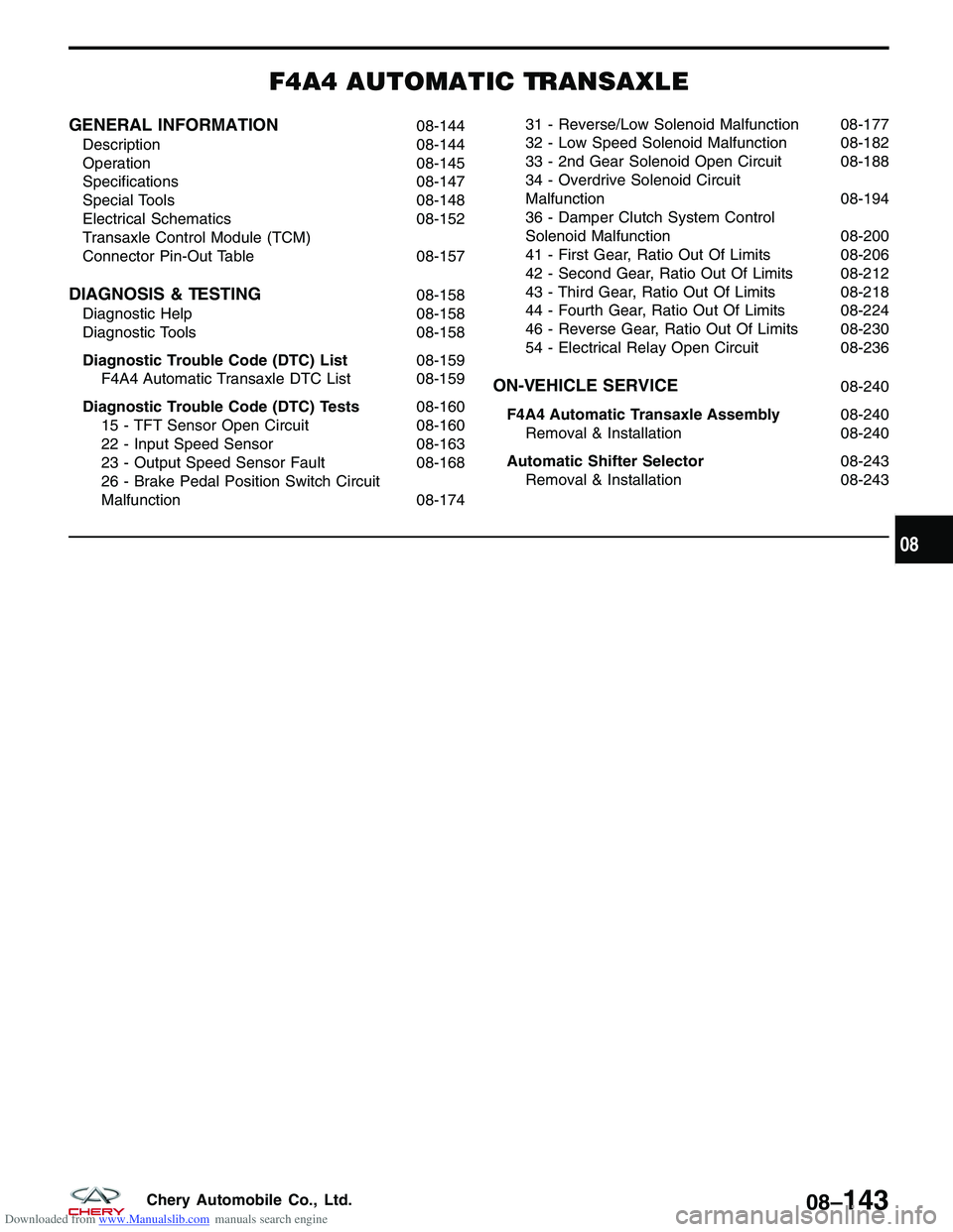
Downloaded from www.Manualslib.com manuals search engine F4A4 AUTOMATIC TRANSAXLE
GENERAL INFORMATION08-144
Description 08-144
Operation 08-145
Specifications 08-147
Special Tools 08-148
Electrical Schematics 08-152
Transaxle Control Module (TCM)
Connector Pin-Out Table 08-157
DIAGNOSIS & TESTING08-158
Diagnostic Help 08-158
Diagnostic Tools 08-158
Diagnostic Trouble Code (DTC) List 08-159
F4A4 Automatic Transaxle DTC List 08-159
Diagnostic Trouble Code (DTC) Tests 08-160
15 - TFT Sensor Open Circuit 08-160
22 - Input Speed Sensor 08-163
23 - Output Speed Sensor Fault 08-168
26 - Brake Pedal Position Switch Circuit
Malfunction 08-17431 - Reverse/Low Solenoid Malfunction 08-177
32 - Low Speed Solenoid Malfunction 08-182
33 - 2nd Gear Solenoid Open Circuit 08-188
34 - Overdrive Solenoid Circuit
Malfunction
08-194
36 - Damper Clutch System Control
Solenoid Malfunction 08-200
41 - First Gear, Ratio Out Of Limits 08-206
42 - Second Gear, Ratio Out Of Limits 08-212
43 - Third Gear, Ratio Out Of Limits 08-218
44 - Fourth Gear, Ratio Out Of Limits 08-224
46 - Reverse Gear, Ratio Out Of Limits 08-230
54 - Electrical Relay Open Circuit 08-236
ON-VEHICLE SERVICE08-240
F4A4 Automatic Transaxle Assembly 08-240
Removal & Installation 08-240
Automatic Shifter Selector 08-243
Removal & Installation 08-243
08
08–143Chery Automobile Co., Ltd.