Page 1603 of 1903
Downloaded from www.Manualslib.com manuals search engine CHIME
Description
The chime is located in the Instrument Cluster (IC). The chime warning system is an audible notification to the driver.
The chime warning system is designed to alert the driver of a vehicle problem or condition.
Operation
The Instrument Cluster (IC) uses hard wired inputs from various sensors and switches to activate the chime. The
sensors and switches are located throughout the vehicle. The following conditions will cause the chime to operate:
•Turn signal on
• Hazard warning flashers on
• Seat belt unbuckled
• Low fuel level
• Low oil pressure
• Low brake fluid level
• Doors unlocked
CHIME
15
15–19Chery Automobile Co., Ltd.
Page 1622 of 1903

Downloaded from www.Manualslib.com manuals search engine BODY CONTROL MODULE - BCM
Description
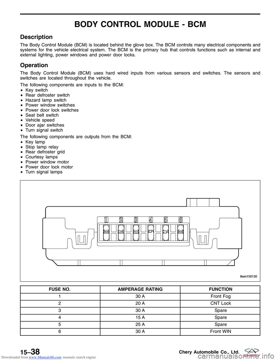
The Body Control Module (BCM) is located behind the glove box. The BCM controls many electrical components and
systems for the vehicle electrical system. The BCM is the primary hub that controls functions such as internal and
external lighting, power windows and power door locks.
Operation
The Body Control Module (BCM) uses hard wired inputs from various sensors and switches. The sensors and
switches are located throughout the vehicle.
The following components are inputs to the BCM:
•Key switch
• Rear defroster switch
• Hazard lamp switch
• Power window switches
• Power door lock switches
• Seat belt switch
• Vehicle speed
• Door ajar switches
• Turn signal switch
The following components are outputs from the BCM:
• Key lamp
• Stop lamp relay
• Rear defroster grid
• Courtesy lamps
• Power window motor
• Power door lock motor
• Turn signal lamps
FUSE NO. AMPERAGE RATING FUNCTION
1 30 AFront Fog
2 20 ACNT Lock
3 30 A Spare
4 15 A Spare
5 25 A Spare
6 30 AFront WIN
LTSM150130
15–38Chery Automobile Co., Ltd.
Page 1648 of 1903

Downloaded from www.Manualslib.com manuals search engine DIAGNOSIS & TESTING
Clearing Service Monitor Lamp
Perform the following to clear the service monitor lamp:1. Turn the ignition switch off.
2. Press down and hold the Mode switch.
3. Turn the ignition switch on.
4. Release the Mode switch.
5. Press the Mode switch and the Clock switch simultaneously within 30 seconds and hold less than 2 seconds to clear the mileage maintenance identification.
Diagnostic Help
1. The X-431 scan tool connects to the Data Link Connector (DLC) and communicates with the vehicle electronicmodules through the class two serial data circuit.
2. Confirm that the malfunction is current and carry-out the diagnostic tests and repair procedures.
3. If the DTC cannot be deleted, it is a current fault.
4. Use a digital multimeter to perform voltage readings on electronic systems.
5. Refer to any Technical Bulletins that issued.
6. Visually inspect the related electrical wiring harness.
7. Inspect and clean all Instrument Cluster (IC) grounds that are related to the DTC.
8. If numerous trouble codes were set, use the electrical schematic and look for any common ground circuits or voltage supply circuits that may apply to the DTC.
Intermittent DTC Troubleshooting
If the failure is intermittent, perform the following:
•Check for loose connectors.
• Look for any chafed, pierced, pinched, or partially broken wires.
• Monitor the scan tool data relative to this circuit.
• Wiggle the related electrical wiring harness and connectors while looking for an interrupted signal on the
affected circuit.
• If possible, try to duplicate the conditions under which the DTC set.
• Look for the data to change or for the DTC to reset during the wiggle test.
• Look for broken, bent, pushed out or corroded terminals.
• Inspect the sensor and mounting area for any condition that would result in an incorrect signal, such as dam-
age or foreign material.
• A data recorder, and/or oscilloscope should be used to help diagnose intermittent conditions.
Ground Inspection
Ground connections are very important to the proper operation of electrical and electronic circuits. Ground connec-
tions are often exposed to moisture, dirt and other corrosive elements. The corrosion (rust) can become an unwanted
resistance. This added resistance can alter the way a circuit works.
Electronically controlled circuits are very sensitive to proper grounding. A loose or corroded ground can drastically
affect an electronically controlled circuit. A poor or corroded ground can effect the circuit. Perform the following when
inspecting a ground connection:
1. Remove the ground bolt or screw.
2. Inspect all mating surface for tarnish, dirt, rust, etc.
3. Clean as required to assure good contact.
4. Reinstall bolt or screw securely.
5. Inspect for �add-on�accessories which may be interfering with the ground circuit.
6. If several wires are crimped into one ground eyelet terminal, check for proper crimps. Make sure all of the wires are clean, securely fastened and providing a good ground path. If multiple wires are crimped to one eyelet, make
sure no excess wire insulation has been crimped creating a bad ground.
15–64Chery Automobile Co., Ltd.
Page 1669 of 1903
Downloaded from www.Manualslib.com manuals search engine INTERIOR LAMPS
Description
The interior lamps consist of the following:
•Key Hole Lamp
• Front Room Lamp
• Middle/Rear Courtesy/Dome Lamp
• Front Step Lamp
• Backlight Adjusting Switch
• Instrument Cluster
• Headlamp Aiming Switch
• Heated Seat Switch (LH)
• Heated Seat Switch (RH)
• Air Control Panel
• Front Fog Lamp Switch
• Rear Fog Lamp Switch
• Console Power Socket (Illumination)
• Door Mirror Remote Control Switch
• Main Power Window And Door Lock/Unlock Switch
• Front Power Window Switch (RH)
• Rear Power Window Switch (LH)
• Rear Power Window Switch (RH)
• Audio
Operation
The key hole lamp and front/middle/rear courtesy lamps are controlled by the BCM. Front step lamps are controlled
by the door lock switch. When the door is open, the front step lamp will light up automatically. Other lamps are
controlled by the lighting and turn signal switch.
15
15–85Chery Automobile Co., Ltd.
Page 1729 of 1903

Downloaded from www.Manualslib.com manuals search engine BODY EXTERIOR
BODY DIMENSIONS15-147
Description 15-147
Front Body Structure 15-148
Dimension of Engine Compartment
(Units: mm) 15-148
Front Structure 15-151
Dimension of Front Structure (Units:
mm) 15-151
Frame 15-153
Body Frame Dimensions (Units: mm) 15-153
Vehicle Clearance 15-154
Front View 15-154
Body 15-157
Side View 15-157
BUMPERS15-166
Front Bumper 15-166
Removal & Installation 15-166
DOORS15-167
Specification 15-167
Front Door 15-168
Removal & Installation 15-168
Disassembly 15-168
Assembly 15-172
Front Door Adjustment 15-172
Replacing Front Door Hinge 15-172
Rear Door 15-173
Removal & Installation 15-173
Disassembly 15-173
Assembly 15-174
Rear Door Adjustment 15-174
Replacing Rear Door Hinge 15-175
Back Cargo Door 15-175
Removal & Installation 15-175
Disassembly 15-175
Assembly 15-177
Back Cargo Door Adjustment 15-177
Replacing Rear Door Hinge 15-177
EXTERIOR LAMPS15-178
Description 15-178
Operation 15-178
Specification 15-178
Electrical Schematics 15-179
Front Combination Lamp Assembly 15-189
Removal & Installation 15-189
Headlamp Adjustment Procedure 15-190
Rear Combination Lamp Assembly 15-190
Removal & Installation 15-190Headlamp
15-191
Removal & Installation 15-191
Front Fog Lamp 15-192
Removal & Installation 15-192
Rear Fog Lamp 15-193
Removal & Installation 15-193
Tail/Backup/Stop Lamp 15-194
Removal & Installation 15-194
Turn Signal Lamp 15-195
Removal & Installation 15-195
High Mounted Stop Lamp 15-197
Removal & Installation 15-197
License Plate Lamp 15-197
Removal & Installation 15-197
FENDER15-199
Front Fender 15-199
Removal & Installation 15-199
FUEL DOOR15-200
Fuel Door 15-200
Removal & Installation 15-200
GRILLE15-201
Grille 15-201
Removal & Installation 15-201
HOOD15-202
Hood 15-202
Removal & Installation 15-202
Hood Adjustment 15-202
Hood Release Cable 15-203
Removal & Installation 15-203
LUGGAGE RACK15-204
Luggage Rack 15-204
Removal & Installation 15-204
SPARE TIRE SUPPORT15-205
Spare Tire Support 15-205
Removal & Installation 15-205
HORN15-206
Description 15-206
Operation 15-206
Electrical Schematics 15-207
Horn 15-208
Removal & Installation 15-208
15
15–145Chery Automobile Co., Ltd.
Page 1762 of 1903

Downloaded from www.Manualslib.com manuals search engine EXTERIOR LAMPS
Description
The exterior lamps consist of the following:
•Headlamps
• Rear Combination Lamps
• Side Repeater Lamps
• Fog Lamps
• Stop Lamps
• Backup Lamps
Operation
•Front Combination Lamp: With the light switch in the 2nd position, the Body Control Module (BCM) receives
input requesting head lamp operation. The BCM then supplies power to the head lamps.
• Turn Signal Lamp: When the turn signal switch is in LH or RH position with the ignition switch in the ON posi-
tion, the FBCM detects the RH or LH turn signal request. The BCM supplies power to the respective turn signal
lamp.
• Hazard Lamp: When the hazard switch is in the ON position, the BCM detects the hazard switch signal. The
BCM outputs the flasher signal (right and left). The BCM then activates the hazard indicator and audible
buzzer.
• Fog Lamp: When the front/rear fog lamp switch is in the ON position and also the light switch is in the 1st or
2nd position. The BCM receives input requesting fog lamp operation. The BCM then supplies power to the fog
lamps.
• Stop Lamp: When the brake pedal is applied, the stop lamp switch sends the signal to the RBCM. The RBCM
then supplies power to the stop lamps.
• Backup Lamp: When the BCM receives the signal from the backup lamp switch, then the BCM supplies power
to the backup lamp.
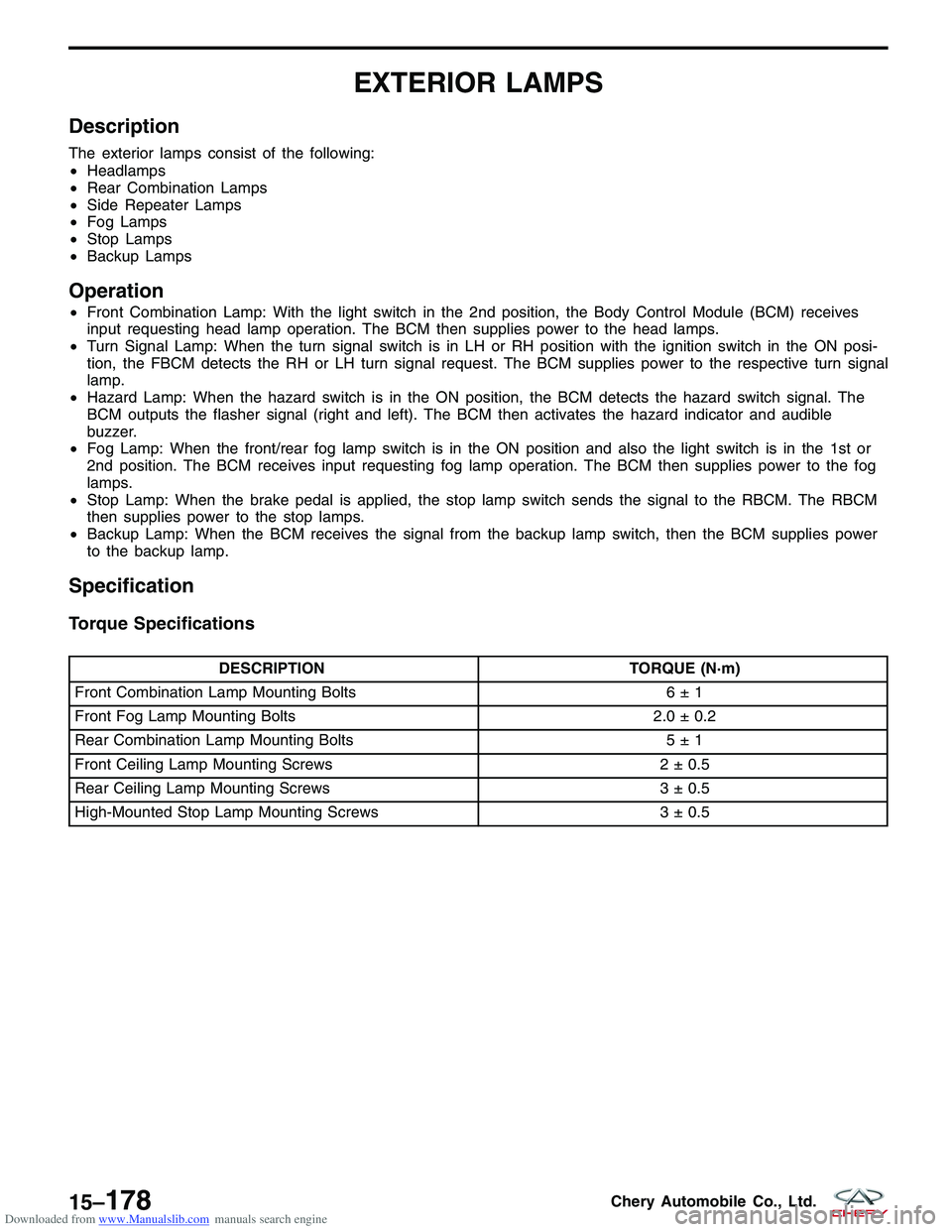
Specification
Torque Specifications
DESCRIPTION TORQUE (N·m)
Front Combination Lamp Mounting Bolts 6 ± 1
Front Fog Lamp Mounting Bolts 2.0 ± 0.2
Rear Combination Lamp Mounting Bolts 5 ± 1
Front Ceiling Lamp Mounting Screws 2 ± 0.5
Rear Ceiling Lamp Mounting Screws 3 ± 0.5
High-Mounted Stop Lamp Mounting Screws 3 ± 0.5
15–178Chery Automobile Co., Ltd.
Page 1769 of 1903
Downloaded from www.Manualslib.com manuals search engine Side Turn Signal and Hazard Warning Lamps (Page 1 of 2)
EXTERIOR LAMPS
LTSMW150022T
15
15–185Chery Automobile Co., Ltd.
Page 1770 of 1903
Downloaded from www.Manualslib.com manuals search engine Turn Signal and Hazard Warning Lamps (Page 2 of 2)
EXTERIOR LAMPS
LTSMW150023T
15–186Chery Automobile Co., Ltd.