2009 CHERY TIGGO turn signal
[x] Cancel search: turn signalPage 1773 of 1903
Downloaded from www.Manualslib.com manuals search engine Front Combination Lamp Assembly
Removal & Installation
1. Open the hood.
2. Disconnect the turn signal lamp.
3. Disconnect the high/low beam front combinationlamp.
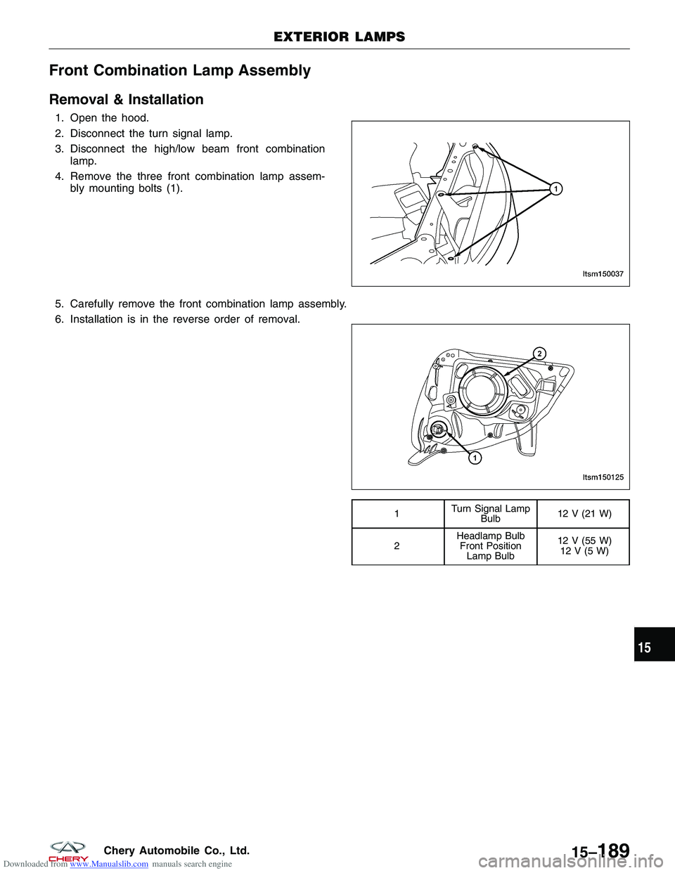
4. Remove the three front combination lamp assem- bly mounting bolts (1).
5. Carefully remove the front combination lamp assembly.
6. Installation is in the reverse order of removal.
1 Turn Signal Lamp
Bulb 12 V (21 W)
2 Headlamp Bulb
Front Position Lamp Bulb 12 V (55 W)
12V(5W)
EXTERIOR LAMPS
LTSM150037
LTSM150125
15
15–189Chery Automobile Co., Ltd.
Page 1775 of 1903
Downloaded from www.Manualslib.com manuals search engine 4. Disconnect the rear combination lamp.
5. Carefully remove the rear combination lamp assembly.
6. Installation is in the reverse order of removal.
Headlamp
Removal & Installation
1. Remove the front combination lamp assembly (See Front Combination Lamp Assembly Removal & Installation inSection 15 Body & Accessories).
2. Remove the headlamp bulb cover.
3. Disconnect the headlamp bulb electrical connector.
4. Remove the headlamp bulb clip.
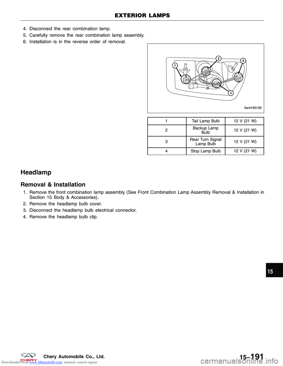
1 Tail Lamp Bulb 12 V (21 W)
2 Backup Lamp
Bulb 12 V (21 W)
3 Rear Turn Signal
Lamp Bulb 12 V (21 W)
4 Stop Lamp Bulb 12 V (21 W)
EXTERIOR LAMPS
LTSM150126
15
15–191Chery Automobile Co., Ltd.
Page 1779 of 1903
Downloaded from www.Manualslib.com manuals search engine Turn Signal Lamp
Removal & Installation
1. Remove the front combination lamp (See Front Combination Lamp Removal & Installation in Section 15 Body &Accessories).
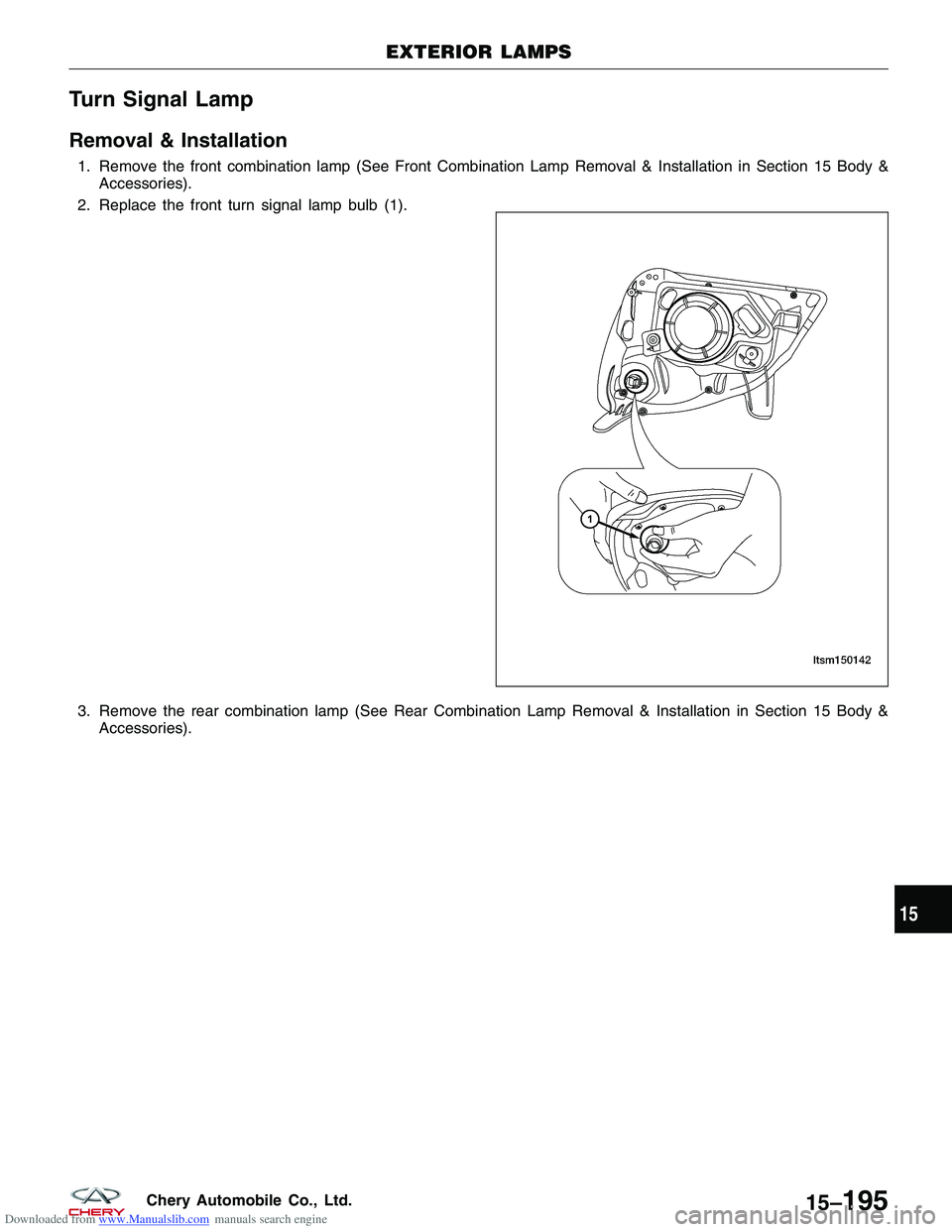
2. Replace the front turn signal lamp bulb (1).
3. Remove the rear combination lamp (See Rear Combination Lamp Removal & Installation in Section 15 Body & Accessories).
EXTERIOR LAMPS
LTSM150142
15
15–195Chery Automobile Co., Ltd.
Page 1780 of 1903
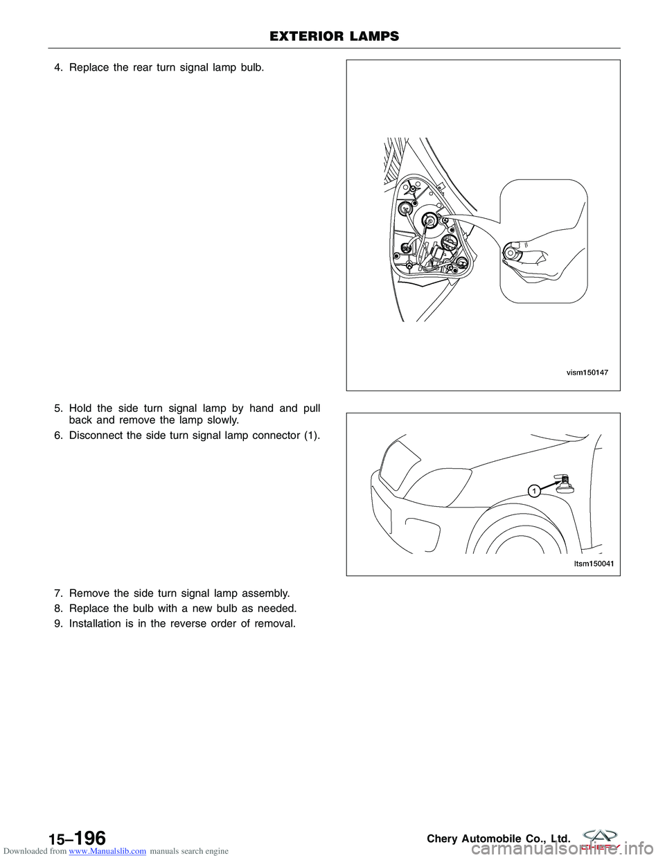
Downloaded from www.Manualslib.com manuals search engine 4. Replace the rear turn signal lamp bulb.
5. Hold the side turn signal lamp by hand and pullback and remove the lamp slowly.
6. Disconnect the side turn signal lamp connector (1).
7. Remove the side turn signal lamp assembly.
8. Replace the bulb with a new bulb as needed.
9. Installation is in the reverse order of removal.
EXTERIOR LAMPS
LTSM150146
LTSM150041
15–196Chery Automobile Co., Ltd.
Page 1875 of 1903
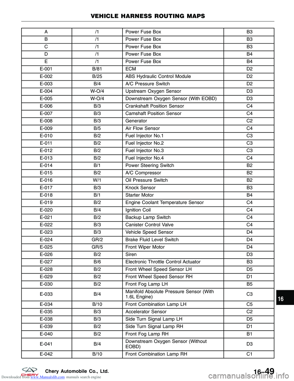
Downloaded from www.Manualslib.com manuals search engine A/1Power Fuse Box B3
B /1Power Fuse Box B3
C /1Power Fuse Box B3
D /1Power Fuse Box B4
E /1Power Fuse Box B4
E-001 B/81 ECM D2
E-002 B/25 ABS Hydraulic Control Module D2
E-003 B/4A/C Pressure Switch D2
E-004 W-O/4 Upstream Oxygen Sensor D3
E-005 W-O/4 Downstream Oxygen Sensor (With EOBD) D3
E-006 B/3Crankshaft Position Sensor C4
E-007 B/3Camshaft Position Sensor C4
E-008 B/3Generator C2
E-009 B/5Air Flow Sensor C4
E-010 B/2Fuel Injector No.1 C3
E-011 B/2Fuel Injector No.2 C3
E-012 B/2Fuel Injector No.3 C3
E-013 B/2Fuel Injector No.4 C4
E-014 B/1Power Steering Switch B2
E-015 B/2A/C Compressor B2
E-016 W/1 Oil Pressure Switch B2
E-017 B/3Knock Sensor B3
E-018 B/1Starter Motor B4
E-019 B/2Engine Coolant Temperature Sensor C4
E-020 B/4Ignition Coil C4
E-021 B/2Backup Lamp Switch C4
E-022 B/3Canister Control Valve C4
E-023 B/3Vehicle Speed Sensor D4
E-024 GR/2 Brake Fluid Level Switch D4
E-025 GR/5 Front Wiper Motor D4
E-026 B/2Siren D3
E-027 B/6Electronic Throttle Control Actuator B3
E-028 B/2Front Wheel Speed Sensor LH D5
E-029 B/2Front Wheel Speed Sensor RH D1
E-030 B/2Front Fog Lamp LH B5
E-033 B/4Manifold Absolute Pressure Sensor (With
1.6L Engine) C3
E-034 B/10 Front Combination Lamp LH C5
E-035 B/3Accelerator Sensor C2
E-038 B/3Side Turn Signal Lamp LH D5
E-039 B/2Side Turn Signal Lamp RH D1
E-040 B/2Front Fog Lamp RH B1
E-041 B/4Downstream Oxygen Sensor (Without
EOBD) D3
E-042 B/10 Front Combination Lamp RH C1
VEHICLE HARNESS ROUTING MAPS
16
16–49Chery Automobile Co., Ltd.
Page 1876 of 1903
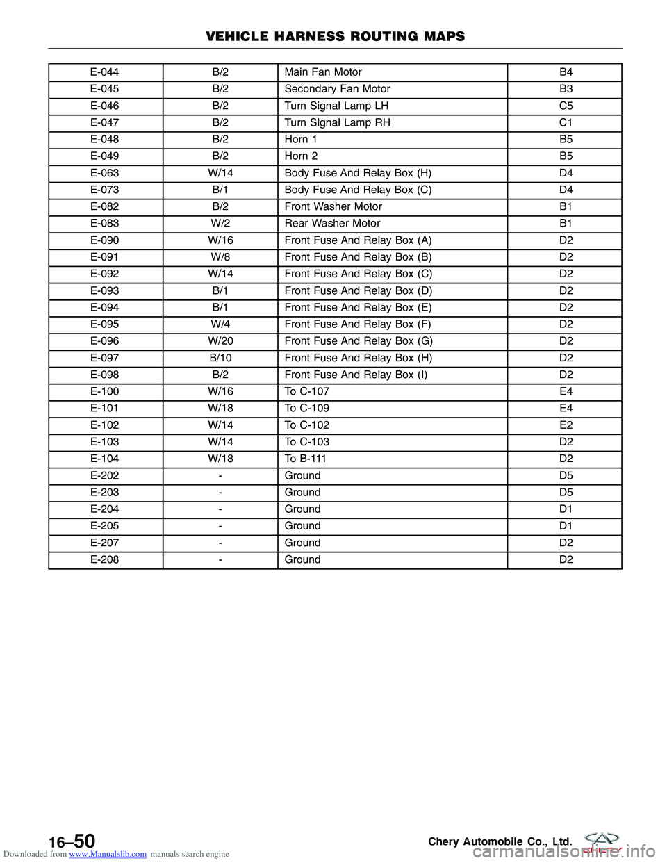
Downloaded from www.Manualslib.com manuals search engine E-044B/2Main Fan Motor B4
E-045 B/2Secondary Fan Motor B3
E-046 B/2Turn Signal Lamp LH C5
E-047 B/2Turn Signal Lamp RH C1
E-048 B/2Horn 1 B5
E-049 B/2Horn 2 B5
E-063 W/14 Body Fuse And Relay Box (H) D4
E-073 B/1Body Fuse And Relay Box (C) D4
E-082 B/2Front Washer Motor B1
E-083 W/2 Rear Washer Motor B1
E-090 W/16 Front Fuse And Relay Box (A) D2
E-091 W/8 Front Fuse And Relay Box (B) D2
E-092 W/14 Front Fuse And Relay Box (C) D2
E-093 B/1Front Fuse And Relay Box (D) D2
E-094 B/1Front Fuse And Relay Box (E) D2
E-095 W/4 Front Fuse And Relay Box (F) D2
E-096 W/20 Front Fuse And Relay Box (G) D2
E-097 B/10 Front Fuse And Relay Box (H) D2
E-098 B/2Front Fuse And Relay Box (I) D2
E-100 W/16 To C-107 E4
E-101 W/18 To C-109 E4
E-102 W/14 To C-102 E2
E-103 W/14 To C-103 D2
E-104 W/18 To B-111 D2
E-202 -Ground D5
E-203 -Ground D5
E-204 -Ground D1
E-205 -Ground D1
E-207 -Ground D2
E-208 -Ground D2
VEHICLE HARNESS ROUTING MAPS
16–50Chery Automobile Co., Ltd.
Page 1882 of 1903
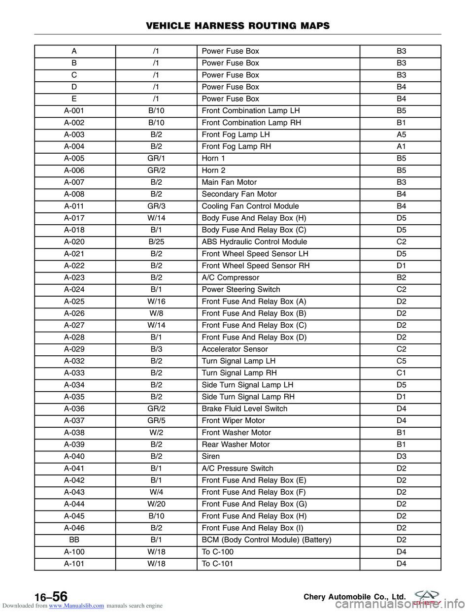
Downloaded from www.Manualslib.com manuals search engine A/1Power Fuse Box B3
B /1Power Fuse Box B3
C /1Power Fuse Box B3
D /1Power Fuse Box B4
E /1Power Fuse Box B4
A-001 B/10 Front Combination Lamp LH B5
A-002 B/10 Front Combination Lamp RH B1
A-003 B/2Front Fog Lamp LH A5
A-004 B/2Front Fog Lamp RH A1
A-005 GR/1 Horn 1 B5
A-006 GR/2 Horn 2 B5
A-007 B/2Main Fan Motor B3
A-008 B/2Secondary Fan Motor B4
A-011 GR/3 Cooling Fan Control Module B4
A-017 W/14 Body Fuse And Relay Box (H) D5
A-018 B/1Body Fuse And Relay Box (C) D5
A-020 B/25 ABS Hydraulic Control Module C2
A-021 B/2Front Wheel Speed Sensor LH D5
A-022 B/2Front Wheel Speed Sensor RH D1
A-023 B/2A/C Compressor B2
A-024 B/1Power Steering Switch C2
A-025 W/16 Front Fuse And Relay Box (A) D2
A-026 W/8 Front Fuse And Relay Box (B) D2
A-027 W/14 Front Fuse And Relay Box (C) D2
A-028 B/1Front Fuse And Relay Box (D) D2
A-029 B/3Accelerator Sensor C2
A-032 B/2Turn Signal Lamp LH C5
A-033 B/2Turn Signal Lamp RH C1
A-034 B/2Side Turn Signal Lamp LH D5
A-035 B/2Side Turn Signal Lamp RH D1
A-036 GR/2 Brake Fluid Level Switch D4
A-037 GR/5 Front Wiper Motor D4
A-038 W/2 Front Washer Motor B1
A-039 B/2Rear Washer Motor B1
A-040 B/2Siren D3
A-041 B/1A/C Pressure Switch D2
A-042 B/1Front Fuse And Relay Box (E) D2
A-043 W/4 Front Fuse And Relay Box (F) D2
A-044 W/20 Front Fuse And Relay Box (G) D2
A-045 B/10 Front Fuse And Relay Box (H) D2
A-046 B/2Front Fuse And Relay Box (I) D2
BB B/1BCM (Body Control Module) (Battery) D2
A-100 W/18 To C-100 D4
A-101 W/18 To C-101 D4
VEHICLE HARNESS ROUTING MAPS
16–56Chery Automobile Co., Ltd.
Page 1902 of 1903
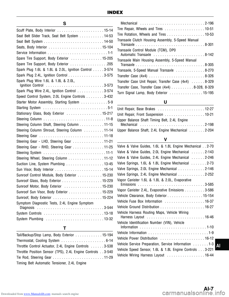
Downloaded from www.Manualslib.com manuals search engine S
Scuff Plate, Body Interior..................... 15-14
Seat Belt Slider Track, Seat Belt System ...........14-53
Seat Belt System ........................... 14-50
Seats, Body Interior ........................ 15-104
Service Information ...........................1-1
Spare Tire Support, Body Exterior ..............15-205
Spare Tire Support, Body Exterior .................205
Spark Plug 1.6L & 1.8L & 2.0L, Ignition Control .....3-574
Spark Plug 2.4L, Ignition Control ................3-575
Spark Plug Wire 1.6L & 1.8L & 2.0L, Ignition Control .......................... 3-573
Spark Plug Wire 2.4L, Ignition Control ............3-574
Speed Control System, 2.0L Engine Controls ........3-432
Starter Motor Assembly, Starting System ............5-9
Starting System .............................5-1
Stationary Glass, Body Exterior ................15-217
Steering Column ............................ 11-8
Steering Column Shaft, Steering Column ...........11-15
Steering Column Shroud, Steering Column .........11-14
Steering Gear ............................. 11-18
Steering Gear - LHD, Steering Gear ..............11-21
Steering Gear - RHD, Steering Gear ..............11-25
Steering System ............................ 11-1
Steering Wheel, Steering Column ................11-12
Suction Line, System Plumbing .................13-45
Sun Visor, Body Interior ...................... 15-14
Sunroof Control Module, Body Exterior ...........15-230
Sunroof Glass, Body Exterior ..................15-229
Sunroof Motor, Body Exterior .................15-230
Sunroof Sun Visor, Body Exterior ...............15-229
Sunroof, Body Exterior ...................... 15-224
Symptom Diagnostic Tests, 2.4L Engine Symptom Diagnosis .............................. 3-544
System Controls ........................... 13-18
System Plumbing .......................... 13-32
T
Tail/Backup/Stop Lamp, Body Exterior ............15-194
Thermostat, Cooling System ....................6-14
Throttle Control Actuator, 2.4L Engine Controls ......3-538
Throttle Position Sensor (TPS), 2.4L Engine Controls . . 3-540
Tie Rod, Steering Gear ....................... 11-29
Timing Belt Automatic Tensioner, 2.4L Engine Mechanical
............................. 2-196
Tire Repair, Wheels and Tires ..................10-51
Tire Rotation, Wheels and Tires .................10-53
Transaxle Clutch Housing Assembly, 5-Speed Manual Transaxle ............................... 8-301
Transaxle Control Module (TCM), DP0 Automatic Transaxle ....................... 8-142
Transaxle Main Housing Assembly, 5-Speed Manual Transaxle ............................... 8-305
Transaxle, 5-Speed Manual Transaxle .............8-270
Transfer Case (4x4) ......................... 8-326
Transfer Case Unit Repair, Transfer Case (4x4) ......8-329
Transfer Case, Transfer Case (4x4) ..........8-328, 8-329
Turn Signal Lamp, Body Exterior ...............15-195
U
Unit Repair, Base Brakes ..................... 12-27
Unit Repair, Front Suspension ..................10-21
Upper Balance Shaft Timing Belt, 2.4L Engine Mechanical ............................. 2-198
Upper Balance Shaft, 2.4L Engine Mechanical .......2-204
V
Valve & Valve Guides, 1.6L & 1.8L Engine Mechanical . . 2-70
Valve & Valve Guides, 2.0L Engine Mechanical ......2-143
Valve & Valve Guides, 2.4L Engine Mechanical ......2-246
Valve Springs, 1.6L & 1.8L Engine Mechanical .......2-73
Valve Springs, 2.0L Engine Mechanical ............2-146
Valve Springs, 2.4L Engine Mechanical ............2-252
Vapor Canister 1.6L & 1.8L & 2.0L, Evaporative Emissions .............................. 3-585
Vapor Canister 2.4L, Evaporative Emissions .........3-586
Vehicle Clearance, Body Exterior ................15-154
Vehicle Fuse Box Information ..................16-37
Vehicle Ground Distribution .................... 16-27
Vehicle Harness Routing Maps, Vehicle Wiring Harness Layout .......................... 16-46
Vehicle Identification Number (VIN), Vehicle Information .............................. 1-10
Vehicle Information ...........................1-9
Vehicle Power Distribution .................... 16-12
Vehicle Service Preparation, Service Information .......1-3
Vehicle Speed Sensor, 1.6L & 1.8L Engine Controls . . . 3-221
Vehicle Wiring Harness Layout .................16-44
INDEX
AI
AI-7