Page 17 of 76

INSTRUMENT AND CONTROL FUNCTIONS
3-2
3 To unlock the steering
Push the key in, and then turn it to
ŌĆ£OFFŌĆØ while still pushing it.
WARNING
EWA10060
Never turn the key to ŌĆ£OFFŌĆØ or
ŌĆ£LOCKŌĆØ while the vehicle is moving,
otherwise the electrical systems will
be switched off, which may result in
loss of control or an accident. Make
sure that the vehicle is stopped be-
fore turning the key to ŌĆ£OFFŌĆØ orŌĆ£LOCKŌĆØ.
EAUT2121
Keyhole cover To close the keyhole cover
Insert the key bow into the keyhole cov-
er receptacle as shown, and then turn
the key to ŌĆ£SHUTŌĆØ to close the cover.
To open the keyhole cover
Insert the key bow into the keyhole cov-
er receptacle as shown, and then turn
the key to ŌĆ£OPENŌĆØ to open the cover.
EAU45380
Indicator, indicator lights and
warning light
EAU11020
Turn signal indicator lightŌĆ£ŌĆØ
This indicator light flashes when the
turn signal switch is pushed to the left or
right.
EAU11080
High beam indicator lightŌĆ£ŌĆØ
This indicator light comes on when the
high beam of the headlight is switched
on.
1. Push.
2. Turn.12
ON
OPEN
OPENPUSH
LOCK
OFF
1. Engine trouble warning lightŌĆ£ŌĆØ
2. High beam indicator lightŌĆ£ŌĆØ
3. Turn signal indicator lightŌĆ£ŌĆØ
4. Oil change indicator
OIL
CHANGE
12 3 4
U4P7E1E0.book Page 2 Wednesday, December 12, 2007 9:37 AM
Page 18 of 76
 to indicate
that the engine oil should be changed.
After changing")
INSTRUMENT AND CONTROL FUNCTIONS
3-3
3
EAU45400
Oil change indicator
This indicator changes from green to
red every 2000 km (1200 mi) to indicate
that the engine oil should be changed.
After changing the engine oil, push the
oil change indicator reset switch in with
the main switch key.
If the engine oil is changed before the
2000 km (1200 mi) interval, the indica-
tor must be reset after the oil change for
the next periodic oil change to be indi-
cated at the correct time.
NOTE:After resetting the oil change indicator
reset switch, the indicator changesfrom red to green.CAUTION:
ECA10280
After 1000 km (600 mi) of operation,the engine oil must be changed.
EAUT1931
Engine trouble warning lightŌĆ£ŌĆØ
This warning light flashes or stays on
when an electrical circuit monitoring the
engine is defective. When this occurs,
have a Yamaha dealer check the self-
diagnosis system.
The electrical circuit of the warning light
can be checked by turning the key to
ŌĆ£ONŌĆØ. If the warning light does not come
on for a few seconds, then go off, have
a Yamaha dealer check the electrical
circuit.
EAUT1821
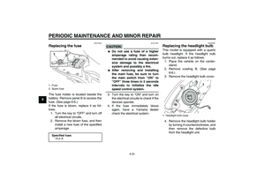
Speedometer unit The speedometer unit is equipped with
a speedometer and an odometer. The
speedometer shows the riding speed.
The odometer shows the total distance
traveled.
1. Oil change indicator
2. Oil change indicator reset switch1
2
1. Speedometer
2. Odometer
OIL
CHANGE2 1
U4P7E1E0.book Page 3 Wednesday, December 12, 2007 9:37 AM
Page 19 of 76
INSTRUMENT AND CONTROL FUNCTIONS
3-4
3
EAU12090
Self-diagnosis device This model is equipped with a self-diag-
nosis device for various electrical cir-
cuits.
If any of those circuits are defective, the
engine trouble warning light will come
on or flash. If this occurs, have a
Yamaha dealer check the vehicle.CAUTION:
ECA11170
To prevent engine damage, be sure
to consult a Yamaha dealer as soonas possible if this occurs.
EAU45630
Fuel gauge The fuel gauge indicates the amount of
fuel in the fuel tank. The needle moves
towards ŌĆ£EŌĆØ (Empty) as the fuel level
decreases. When the needle reaches
the red line, refuel as soon as possible.NOTE:Turning the key to ŌĆ£OFFŌĆØ cancels thefuel gauge reading.
EAU12331
Anti-theft alarm (optional) This model can be equipped with an
optional anti-theft alarm by a Yamaha
dealer. Contact a Yamaha dealer for
more information.
1. Fuel gauge
2. Red line
OIL
CHANGE
1
2
U4P7E1E0.book Page 4 Wednesday, December 12, 2007 9:37 AM
Page 20 of 76

INSTRUMENT AND CONTROL FUNCTIONS
3-5
3
EAU12347
Handlebar switches Left
Right
EAU12400
Dimmer switchŌĆ£/ŌĆØ
Set this switch toŌĆ£ŌĆØ for the high
beam and toŌĆ£ŌĆØ for the low beam.
EAU12460
Turn signal switchŌĆ£/ŌĆØ
To signal a right-hand turn, push this
switch toŌĆ£ŌĆØ. To signal a left-hand
turn, push this switch toŌĆ£ŌĆØ. When re-
leased, the switch returns to the center
position. To cancel the turn signal
lights, push the switch in after it has re-
turned to the center position.
EAU12500
Horn switchŌĆ£ŌĆØ
Press this switch to sound the horn.
EAU12720
Start switchŌĆ£ŌĆØ
With the sidestand up, push this switch
while applying the front or rear brake to
crank the engine with the starter.CAUTION:
ECA10050
See page 5-1 for starting instruc-tions prior to starting the engine.
EAU12900
Front brake lever The front brake lever is located on the
right handlebar grip. To apply the front
brake, pull this lever toward the handle-
bar grip.
1. Dimmer switchŌĆ£/ŌĆØ
2. Turn signal switchŌĆ£/ŌĆØ
3. Horn switchŌĆ£ŌĆØ
1. Start switchŌĆ£ŌĆØ
2 13
1
1. Front brake lever
1
U4P7E1E0.book Page 5 Wednesday, December 12, 2007 9:37 AM
Page 21 of 76
INSTRUMENT AND CONTROL FUNCTIONS
3-6
3
EAU12950
Rear brake lever The rear brake lever is located on the
left handlebar grip. To apply the rear
brake, pull this lever toward the handle-
bar grip.
EAU45390
Fuel tank cap To remove the fuel tank cap
1. Open the seat. (See page 3-8.)
2. Open the fuel tank cap lid.
3. Turn the fuel tank cap counter-
clockwise and pull it off.
To install the fuel tank cap
1. Insert the fuel tank cap into the
tank opening and turn it clockwise
until theŌĆ£ŌĆØ marks on the cap
and tank are aligned.
2. Close the fuel tank cap lid.
3. Close the seat.
WARNING
EWA11090
Make sure that the fuel tank cap isproperly closed before riding.
1. Rear brake lever
1
1. Fuel tank cap lid
2. Fuel tank cap
2
1
U4P7E1E0.book Page 6 Wednesday, December 12, 2007 9:37 AM
Page 22 of 76

INSTRUMENT AND CONTROL FUNCTIONS
3-7
3
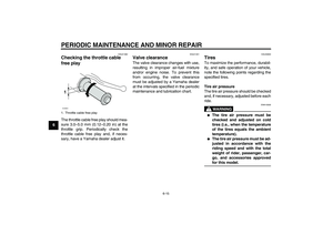
EAU13220
Fuel Make sure that there is sufficient fuel in
the tank. When refueling, be sure to in-
sert the pump nozzle into the fuel tank
filler hole and to fill the tank to the bot-
tom of the filler tube as shown.
WARNING
EWA10880
�
Do not overfill the fuel tank, oth-
erwise it may overflow when the
fuel warms up and expands.
�
Avoid spilling fuel on the hot en-gine.
CAUTION:
ECA10070
Immediately wipe off spilled fuel
with a clean, dry, soft cloth, since
fuel may deteriorate painted surfac-es or plastic parts.
EAU33520
CAUTION:
ECA11400
Use only unleaded gasoline. The use
of leaded gasoline will cause severe
damage to internal engine parts,
such as the valves and piston rings,as well as to the exhaust system.
Your Yamaha engine has been de-
signed to use regular unleaded gaso-
line with a research octane number of
91 or higher. If knocking (or pinging) oc-
curs, use a gasoline of a different brandor premium unleaded fuel. Use of un-
leaded fuel will extend spark plug life
and reduce maintenance costs.
1. Fuel tank filler tube
2. Fuel level
2 1
Recommended fuel:
REGULAR UNLEADED GASOLINE
ONLY
Fuel tank capacity:
5.5 L (1.45 US gal) (1.21 Imp.gal)
U4P7E1E0.book Page 7 Wednesday, December 12, 2007 9:37 AM
Page 23 of 76

INSTRUMENT AND CONTROL FUNCTIONS
3-8
3
EAU13443
Catalytic converters This vehicle is equipped with catalytic
converters in the exhaust system.
WARNING
EWA10860
The exhaust system is hot after op-
eration. Make sure that the exhaust
system has cooled down before do-ing any maintenance work.CAUTION:
ECA16490
The following precautions must be
observed to prevent a fire hazard or
other damages.�
Use only unleaded gasoline.
The use of leaded gasoline will
cause unrepairable damage to
the catalytic converters.
�
Never park the vehicle near pos-
sible fire hazards such as grass
or other materials that easily
burn.
�
Do not allow the engine to idletoo long.
EAUT1502
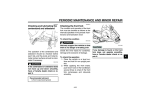
Seat To open the seat
1. Place the scooter on the center-
stand.
2. Insert the key into the main switch,
and then turn it counterclockwise
to the first ŌĆ£OPENŌĆØ position. If the
main switch is in the ŌĆ£LOCKŌĆØ posi-
tion, turn the key counterclockwise
to the second ŌĆ£OPENŌĆØ position.NOTE:Do not push inward when turning the
key from ŌĆ£OFFŌĆØ to ŌĆ£OPENŌĆØ or fromŌĆ£LOCKŌĆØ to ŌĆ£OPENŌĆØ.
3. Fold the seat up.To close the seat
1. Fold the seat down, and then push
it down to lock it in place.
2. Remove the key from the main
switch if the scooter will be left un-
attended.
NOTE:Make sure that the seat is properly se-cured before riding.
1. Seat open position
ON
OPEN
OPENP
U
S
HLOCKOFF
ON
OPEN
OPENP
U
S
HLOCKOFF
1
1
U4P7E1E0.book Page 8 Wednesday, December 12, 2007 9:37 AM
Page 24 of 76
INSTRUMENT AND CONTROL FUNCTIONS
3-9
3
EAU37480
Helmet holders The helmet holders are located under
the seat.
To secure a helmet to a helmet hold-
er
1. Open the seat. (See page 3-8.)
2. Attach a helmet to a helmet holder,
and then securely close the seat.
WARNING
EWA10160
Never ride with a helmet attached to
the helmet holder, since the helmet
may hit objects, causing loss of con-trol and possibly an accident.To release a helmet from a helmet
holder
Open the seat, remove the helmet from
the helmet holder, and then close the
seat.
EAUT1712
Storage compartments Front storage compartment
WARNING
EWA11191
�
Do not exceed the load limit of
1.5 kg (3.3 lb) for the front stor-
age compartment.
�
Do not exceed the maximum
load of 167 kg (368 lb) for the ve-hicle.
1. Helmet holder
1
1. Front storage compartment
1
U4P7E1E0.book Page 9 Wednesday, December 12, 2007 9:37 AM


2. Attach a helm")