Page 25 of 76

CAUTION:
ECAT1030
Keep the following points in mind
when usin")
INSTRUMENT AND CONTROL FUNCTIONS
3-10
3 Rear storage compartment
The rear storage compartment is locat-
ed under the seat. (See page 3-8.)
CAUTION:
ECAT1030
Keep the following points in mind
when using the storage compart-
ment.�
Since the storage compartment
accumulates heat when ex-
posed to the sun, do not store
anything susceptible to heat in-
side it.
�
To avoid humidity from spread-
ing through the storage com-
partment, wrap wet articles in a
plastic bag before storing them
in the compartment.
�
Since the storage compartment
may get wet while the scooter is
being washed, wrap any articles
stored in the compartment in a
plastic bag.
�
Do not keep anything valuable
or breakable in the storage com-partment.WARNING
EWAT1051
�
Do not exceed the load limit of 5
kg (11 lb) for the rear storage
compartment.
�
Do not exceed the maximum
load of 167 kg (368 lb) for the ve-hicle.
EAU15111
Carrier
WARNING
EWA10171
�
Do not exceed the load limit of 5
kg (11 lb) for the carrier.
�
Do not exceed the maximum
load of 167 kg (368 lb) for the ve-hicle.
1. Rear storage compartment
1
1. Carrier
1
U4P7E1E0.book Page 10 Wednesday, December 12, 2007 9:37 AM
Page 26 of 76
 for the luggage
hook.
�
Do not exceed the maximum
load of 167 kg (368")
INSTRUMENT AND CONTROL FUNCTIONS
3-11
3
EAUT1071
Luggage hook
WARNING
EWAT1031
�
Do not exceed the load limit of
1.0 kg (2.2 lb) for the luggage
hook.
�
Do not exceed the maximum
load of 167 kg (368 lb) for the ve-hicle.
EAU15301
Sidestand The sidestand is located on the left side
of the frame. Raise the sidestand or
lower it with your foot while holding the
vehicle upright.NOTE:The built-in sidestand switch is part of
the ignition circuit cut-off system, which
cuts the ignition in certain situations.
(See further down for an explanation ofthe ignition circuit cut-off system.)
WARNING
EWA10240
The vehicle must not be ridden with
the sidestand down, or if the side-
stand cannot be properly moved up(or does not stay up), otherwise the
sidestand could contact the ground
and distract the operator, resulting
in a possible loss of control.
Yamaha’s ignition circuit cut-off
system has been designed to assist
the operator in fulfilling the respon-
sibility of raising the sidestand be-
fore starting off. Therefore, check
this system regularly as described
below and have a Yamaha dealer re-
pair it if it does not function proper-
ly.
1. Luggage hook
1
1. Sidestand
1
U4P7E1E0.book Page 11 Wednesday, December 12, 2007 9:37 AM
Page 27 of 76
INSTRUMENT AND CONTROL FUNCTIONS
3-12
3
EAUT1092
Ignition circuit cut-off system Check the operation of the sidestand
switch against the information below.
WARNING
EWA10260
�
The vehicle must be placed on
the centerstand during this in-
spection.
�
If a malfunction is noted, have a
Yamaha dealer check the sys-tem before riding.
Turn the key on.
Put the sidestand up.Push the start switch while applying
either of the brake levers. The engine will
start.Put the sidestand down.
If the engine stalls:
The sidestand switch is OK.
U4P7E1E0.book Page 12 Wednesday, December 12, 2007 9:37 AM
Page 28 of 76
PRE-OPERATION CHECKS
4-1
4
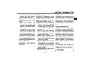
EAU15593
The condition of a vehicle is the owner’s responsibility. Vital components can start to deteriorate quickly and unexpectedly,
even if the vehicle remains unused (for example, as a result of exposure to the elements). Any damage, fluid leakage or loss
of tire air pressure could have serious consequences. Therefore, it is very important, in addition to a thorough visual inspec-
tion, to check the following points before each ride.NOTE:Pre-operation checks should be made each time the vehicle is used. Such an inspection can be accomplished in a very shorttime; and the added safety it assures is more than worth the time involved.
WARNING
EWA11150
If any item in the Pre-operation check list is not working properly, have it inspected and repaired before operatingthe vehicle.U4P7E1E0.book Page 1 Wednesday, December 12, 2007 9:37 AM
Page 29 of 76

PRE-OPERATION CHECKS
4-2
4
EAU15605
Pre-operation check list
ITEM CHECKS PAGE
FuelCheck fuel level in fuel tank.
Refuel if necessary.
Check fuel line for leakage.3-7
Engine oilCheck oil level in engine.
If necessary, add recommended oil to specified level.
Check vehicle for oil leakage.6-9
Final transmission oilCheck vehicle for oil leakage. 6-11
Front brakeCheck operation.
If soft or spongy, have Yamaha dealer bleed hydraulic system.
Check brake pads for wear.
Replace if necessary.
Check fluid level in reservoir.
If necessary, add recommended brake fluid to specified level.
Check hydraulic system for leakage.6-18, 6-19
Rear brakeCheck operation.
Lubricate cable if necessary.
Check lever free play.
Adjust if necessary.6-18, 6-19
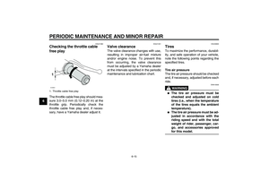
Throttle gripMake sure that operation is smooth.
Check cable free play.
If necessary, have Yamaha dealer adjust cable free play and lubricate cable and
grip housing.6-15, 6-21
Control cablesMake sure that operation is smooth.
Lubricate if necessary.6-20
Wheels and tiresCheck for damage.
Check tire condition and tread depth.
Check air pressure.
Correct if necessary.6-15, 6-17
U4P7E1E0.book Page 2 Wednesday, December 12, 2007 9:37 AM
Page 30 of 76
PRE-OPERATION CHECKS
4-3
4
Brake leversMake sure that operation is smooth.
Lubricate lever pivoting points if necessary.6-21
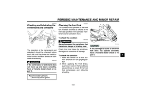
Centerstand, sidestandMake sure that operation is smooth.
Lubricate pivots if necessary.6-22
Chassis fastenersMake sure that all nuts, bolts and screws are properly tightened.
Tighten if necessary.—
Instruments, lights, signals
and switchesCheck operation.
Correct if necessary.—
Sidestand switchCheck operation of ignition circuit cut-off system.
If system is defective, have Yamaha dealer check vehicle.3-11 ITEM CHECKS PAGE
U4P7E1E0.book Page 3 Wednesday, December 12, 2007 9:37 AM
Page 31 of 76

OPERATION AND IMPORTANT RIDING POINTS
5-1
5
EAU15980
WARNING
EWA10870
�
Become thoroughly familiar
with all operating controls and
their functions before riding.
Consult a Yamaha dealer re-
garding any control or function
that you do not thoroughly un-
derstand.
�
Never start the engine or oper-
ate it in a closed area for any
length of time. Exhaust fumes
are poisonous, and inhaling
them can cause loss of con-
sciousness and death within a
short time. Always make sure
that there is adequate ventila-
tion.
�
For safety, always start the en-gine with the centerstand down.
EAU45310
NOTE:This model is equipped with a lean an-
gle sensor to stop the engine in case of
a turnover. To start the engine after a
turnover, be sure to turn the main
switch to “OFF” and then to “ON”. Fail-
ing to do so will prevent the engine from
starting even though the engine willcrank when pushing the start switch.
EAU45420
Starting the engine CAUTION:
ECA10250
See page 5-4 for engine break-in in-
structions prior to operating the ve-hicle for the first time.
In order for the ignition circuit cut-off
system to enable starting, the side-
stand must be up.
WARNING
EWA10290
�
Before starting the engine,
check the function of the igni-
tion circuit cut-off system ac-
cording to the procedure
described on page 3-12.
�
Never ride with the sidestanddown.
1. Turn the key to “ON”.
CAUTION:
ECAT1040
The engine trouble warning light
should come on for a few seconds,
then go off. If the warning light does
not go off, have a Yamaha dealercheck the electrical circuit.
2. Close the throttle completely.
U4P7E1E0.book Page 1 Wednesday, December 12, 2007 9:37 AM
Page 32 of 76

OPERATION AND IMPORTANT RIDING POINTS
5-2
53. Start the engine by pushing the
start switch while applying the front
or rear brake.
NOTE:If the engine does not start, release the
start switch, wait a few seconds, and
then try again. Each starting attempt
should be as short as possible to pre-
serve the battery. Do not crank the en-
gine more than 5 seconds on any oneattempt.
CAUTION:
ECA11040
For maximum engine life, never ac-
celerate hard when the engine iscold!
EAU45091
Starting off 1. While pulling the rear brake lever
with your left hand and holding the
grab bar with your right hand, push
the scooter off the centerstand.
2. Sit astride the seat, and then ad-
just the rear view mirrors.
3. Switch the turn signals on.
4. Check for oncoming traffic, and
then slowly turn the throttle grip (on
the right) in order to take off.
5. Switch the turn signals off.
1. Rear brake lever
2. Start switch
3. Front brake lever
1
23
1. Grab bar
1
U4P7E1E0.book Page 2 Wednesday, December 12, 2007 9:37 AM