Page 41 of 76
PERIODIC MAINTENANCE AND MINOR REPAIR
6-6
6
EAU18712
Removing and installing cowl-
ings and panels The cowlings and panels shown need
to be removed to perform some of the
maintenance jobs described in this
chapter. Refer to this section each time
a cowling or panel needs to be re-
moved and installed.
EAU18851
Cowling A
To remove the cowlingRemove the screws, and then pull the
cowling off as shown.To install the cowling
Place the cowling in the original posi-
tion, and then install the screws.
EAU45470
Cowling B
To remove the cowling1. Remove the screws, and then pull
the cowling off as shown.
2. Disconnect the headlight coupler,
and the auxiliary light lead coupler.
1. Cowling A
2. Cowling B
3. Panel A
4. Panel B
3
4
12
1. Screw
11
1. Screw
1. Screw
1
1
U4P7E1E0.book Page 6 Wednesday, December 12, 2007 9:37 AM
Page 42 of 76
PERIODIC MAINTENANCE AND MINOR REPAIR
6-7
6To install the cowling
1. Connect the headlight coupler,
and the auxiliary light lead coupler.
2. Place the cowling in the original
position, and then install the
screws.
EAU19281
Panel A
To remove the panelRemove the screw, and then pull the
panel off as shown.To install the panel
Place the panel in the original position,
and then install the screw.
EAU45450
Panel B
To remove the panel1. Pull up the floorboard mat.2. Remove the screws, and then pull
the panel off as shown.
To install the panel
1. Place the panel in the original posi-
tion, and then install the screws.
2. Place the floorboard mat in the
original position.
1. Headlight coupler
2. Auxiliary light lead coupler
1
2
1. Screw
1
1. Floorboard mat
1. Screw
1
1
U4P7E1E0.book Page 7 Wednesday, December 12, 2007 9:37 AM
Page 43 of 76

PERIODIC MAINTENANCE AND MINOR REPAIR
6-8
6
EAU45590
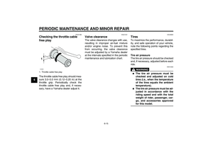
Checking the spark plug The spark plug is an important engine
component, which is easy to check.
Since heat and deposits will cause any
spark plug to slowly erode, the spark
plug should be removed and checked
in accordance with the periodic mainte-
nance and lubrication chart. In addition,
the condition of the spark plug can re-
veal the condition of the engine.
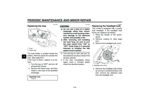
To remove the spark plug
1. Place the vehicle on the center-
stand.
2. Remove panel A. (See page 6-6.)
3. Remove the spark plug cap.
4. Remove the spark plug as shown,
using the spark plug wrench,
which is located in the rear storage
compartment. (See page 3-9.)
To check the spark plug
1. Check that the porcelain insulator
around the center electrode of the
spark plug is a medium-to-light tan
(the ideal color when the vehicle is
ridden normally).
NOTE:If the spark plug shows a distinctly dif-
ferent color, the engine could be oper-
ating improperly. Do not attempt to
diagnose such problems yourself. In-
stead, have a Yamaha dealer checkthe vehicle.
2. Check the spark plug for electrode
erosion and excessive carbon or
other deposits, and replace it if
necessary.
To install the spark plug
1. Measure the spark plug gap with a
wire thickness gauge and, if nec-
essary, adjust the gap to specifica-
tion.
1. Spark plug wrench
1. Spark plug wrench
1
1
Specified spark plug:
NGK/CR7E
U4P7E1E0.book Page 8 Wednesday, December 12, 2007 9:37 AM
Page 44 of 76

PERIODIC MAINTENANCE AND MINOR REPAIR
6-9
62. Clean the surface of the spark plug
gasket and its mating surface, and
then wipe off any grime from the
spark plug threads.
3. Install the spark plug with the
spark plug wrench, and then tight-
en it to the specified torque.
NOTE:If a torque wrench is not available when
installing a spark plug, a good estimate
of the correct torque is 1/4–1/2 turn
past finger tight. However, the spark
plug should be tightened to the speci-fied torque as soon as possible.
4. Install the spark plug cap.
5. Install the panel.
EAU45480
Engine oil The engine oil level should be checked
before each ride. In addition, the oil
must be changed at the intervals spec-
ified in the periodic maintenance and
lubrication chart.
The engine oil must also be changed at
the initial 1000 km (600 mi) and when
the oil change indicator color changes
from green to red. The oil change indi-
cator must be reset after the initial 1000
km (600 mi). (See page 3-2 for reset
procedures.)
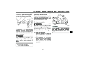
To check the engine oil level
1. Place the vehicle on the center-
stand.NOTE:Make sure that the vehicle is positioned
straight up when checking the oil level.
A slight tilt to the side can result in afalse reading.
2. Start the engine, warm it up for
several minutes, and then turn it
off.
1. Spark plug gapSpark plug gap:
0.7–0.8 mm (0.028–0.031 in)
Tightening torque:
Spark plug:
13 Nm (1.3 m·kgf, 9.4 ft·lbf)
U4P7E1E0.book Page 9 Wednesday, December 12, 2007 9:37 AM
Page 45 of 76

PERIODIC MAINTENANCE AND MINOR REPAIR
6-10
6 3. Wait a few minutes until the oil set-
tles, remove the oil filler cap, wipe
the dipstick clean, insert it back
into the oil filler hole (without
screwing it in), and then remove it
again to check the oil level.
NOTE:The engine oil should be between theminimum and maximum level marks.
4. If the engine oil is below the mini-
mum level mark, add sufficient oil
of the recommended type to raise
it to the correct level.5. Insert the dipstick into the oil filler
hole, and then tighten the oil filler
cap.
To change the engine oil
1. Place the vehicle on the center-
stand.
2. Start the engine, warm it up for
several minutes, and then turn it
off.
3. Place an oil pan under the engine
to collect the used oil.
4. Remove the engine oil filler cap
and drain bolt to drain the oil from
the crankcase.
NOTE:Check the washer for damage and re-place it if necessary.5. Install the engine oil drain bolt, and
then tighten it to the specified
torque.
6. Refill with the specified amount of
the recommended engine oil, and
then install and tighten the engine
oil filler cap.
1. Engine oil filler cap
2. Dipstick
3. Maximum level mark
4. Minimum level mark
32
1 4
1. Engine oil drain bolt
Tightening torque:
Engine oil drain bolt
20 Nm (2.0 m·kgf, 14 ft·lbf)
Recommended engine oil:
See page 8-1.
Oil quantity:
1.00 L (1.06 US qt) (0.88 Imp.qt)
1
U4P7E1E0.book Page 10 Wednesday, December 12, 2007 9:37 AM
Page 46 of 76

PERIODIC MAINTENANCE AND MINOR REPAIR
6-11
6
CAUTION:
ECA11670
�
Do not use oils with a diesel
specification of “CD” or oils of a
higher quality than specified. In
addition, do not use oils labeled
“ENERGY CONSERVING II” or
higher.
�
Be sure no foreign material en-ters the crankcase.
7. Start the engine, and then let it idle
for several minutes while checking
it for oil leakage. If oil is leaking, im-
mediately turn the engine off and
check for the cause.8. Turn the engine off, and then
check the oil level and correct it if
necessary.
9. Reset the oil change indicator.
(See page 3-2 for reset proce-
dures.)
NOTE:If the engine oil is changed before the
oil change indicator color changes from
green to red (i.e. before the periodic oil
change interval has been reached), the
oil change indicator must be reset after
the oil change for the next periodic oil
change to be indicated at the correcttime.
EAU20063
Final transmission oil The final transmission case must be
checked for oil leakage before each
ride. If any leakage is found, have a
Yamaha dealer check and repair the
scooter. In addition, the final transmis-
sion oil must be changed as follows at
the intervals specified in the periodic
maintenance and lubrication chart.
1. Start the engine, warm up the final
transmission oil by riding the
scooter for several minutes, and
then stop the engine.
2. Place the scooter on the center-
stand.
3. Place an oil pan under the final
transmission case to collect the
used oil.
4. Remove the final transmission oil
filler cap and final transmission
drain bolt to drain the oil from the fi-
nal transmission case.
1.“CD” specification
2.“ENERGY CONSERVING II”
1
2
U4P7E1E0.book Page 11 Wednesday, December 12, 2007 9:37 AM
Page 47 of 76

PERIODIC MAINTENANCE AND MINOR REPAIR
6-12
6
5. Install the final transmission oil
drain bolt, and then tighten it to the
specified torque.6. Refill with the specified amount of
the recommended final transmis-
sion oil, and then install and tighten
the oil filler cap.
WARNING
EWA11310
�
Make sure that no foreign mate-
rial enters the final transmission
case.
�
Make sure that no oil gets on thetire or wheel.
7. Check the final transmission case
for oil leakage. If oil is leaking,
check for the cause.
EAU45490
Air filter and V-belt case air fil-
ter elements The air filter element should be re-
placed and the V-belt case air filter ele-
ment should be cleaned at the intervals
specified in the periodic maintenance
and lubrication chart. Service the air fil-
ter elements more frequently if you are
riding in unusually wet or dusty areas.
The air filter check hoses must be fre-
quently checked and cleaned if neces-
sary.
Replacing the air filter element
1. Place the scooter on the center-
stand.
2. Remove the air filter case cover by
removing the screws.
1. Final transmission oil filler cap
1. Final transmission oil drain boltTightening torque:
Final transmission oil drain bolt:
23 Nm (2.3 m·kgf, 17 ft·lbf)
1
1
Recommended final transmission
oil:
See page 8-1.
Oil quantity:
0.13 L (0.14 US qt) (0.11 Imp.qt)
U4P7E1E0.book Page 12 Wednesday, December 12, 2007 9:37 AM
Page 48 of 76

PERIODIC MAINTENANCE AND MINOR REPAIR
6-13
63. Pull the air filter element out.
4. Insert a new air filter element into
the air filter case.
CAUTION:
ECA10480
�
Make sure that the air filter ele-
ment is properly seated in the
air filter case.
�
The engine should never be op-
erated without the air filter ele-
ment installed, otherwise the
piston(s) and/or cylinder(s) maybecome excessively worn.
5. Install the air filter case cover by in-
stalling the screws.
Cleaning the air filter check hoses1. Check the hoses on the rear side
of the air filter case for accumulat-
ed dirt or water.
2. If dirt or water is visible in the air fil-
ter check hoses, remove the
clamps from them, and then re-
move the plugs to drain the hoses.
Cleaning the V-belt case air filter el-
ement
1. Place the scooter on the center-
stand.
2. Remove the screws, and then pull
the V-belt case air filter element
cover outward and away from V-
belt case.
1. Air filter case cover
2. Screw
1. Air filter element
2 1
2
1
1. Air filter check hose
2. Clamp
3. Air filter check hose plug
1
23
1. V-belt case air filter element cover
2. Screw
2 1
U4P7E1E0.book Page 13 Wednesday, December 12, 2007 9:37 AM