Page 9 of 93

86A-9
MR-372-J84-86A050$177.mif
V3
86A
RADIO
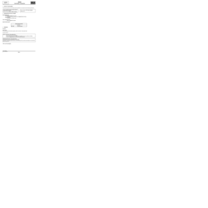
Fault finding - Role of components
Role of main components
–Display: displays various multimedia system data such as the station selected, time, CD listing and satellite
guidance information.
–Steering column control: allows the various system functions to be used via the steering wheel control.
–Speakers and tweeters: relay the sound from the multimedia system into the vehicle.
–CD changer: enables compact discs to be loaded and music to be relayed to the receiver.
–AM/FM aerial: receives radio signals from various transmitters.
–GPS aerial: receives various data transmitted by satellites.
–Radio/navigation computer: manages the various multimedia system functions according to user requests and
transmits audio data to the vehicle via the speakers.
–Cartographic map DVD: loads maps into the navigation computer.
–AM/FM aerial amplifier: improves the reception of AM/FM signals.
–Multimedia network interface unit: enables information to be exchanged between the "vehicle" and "multimedia"
multiplex networks. This computer is involved in activating the multimedia system.
MR-372-J84-86A050$177.mif
LPN RADIO
Vdiag No: C4
Page 10 of 93
86A-10
MR-372-J84-86A050$236.mif
V3
86A
RADIO
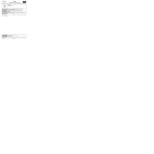
Fault finding - Operating diagram
Layout of the main components of the LPN* Radio system:
*LPN: Low Price NavigationV M multiplex line
diagnostic socketUCH
FEED (Kangoo 2)Electric mirror,
passenger side
(Trafic II ph2)
Other computersMultimedia network
interface unit
Multifunction aerial
(Trafic II ph2)Steering column
control
GPS aerialLPN* radio
navigation
Aerial amplifier
(Espace IV ph2,
Scénic II ph2,
Kangoo 2)Passenger
compartment fuse
box and relay
ABS, ABS/ESP or
wheel speed
computer depending
on equipment levelRadio navigation
display
Microphone
CD changer
(if an option)Speakers
Vehicle multiplex network
Multimedia multiplex network
MR-372-J84-86A050$236.mif
LPN RADIO
Vdiag No: C4
Page 11 of 93
.
–Playing CDs/MP3 C")
86A-11
MR-372-J84-86A050$295.mif
V3
86A
RADIO
Fault finding - Function
General operation
The multimedia system is involved in the following functions:
–Radio reception (AM, FM).
–Playing CDs/MP3 CDs/navigation map.
–Guidance and navigation system with colour screen.
–Bluetooth hands-free phone.
The use of this multimedia system allows the customer:
–To select radio stations by using the preselections, the list or manual selection.
–To have an automatically-updated radio list.
–To listen to CDs or MP3 CDs.
–To control the radio using the steering column switch (satellite).
–To change various acoustic parameters (bass, treble, fader, etc.).
–To navigate on a colour screen (visual and audio guidance): for this function the system uses GPS, the
vehicle speed wire information and an internal gyroscope.
–To receive traffic information via RDS-TMC and to display it on the navigation map. Possibility of re-
routing according to traffic information.
–To display the time and temperature on the screen.
–To use the hands-free phone function (sound relayed to the radio speakers) with a Bluetooth phone (HFP
profile).
–To be protected by an immobiliser code.
MR-372-J84-86A050$295.mif
LPN RADIO
Vdiag No: C4
Page 12 of 93

86A-12
MR-372-J84-86A050$354.mif
V3
86A
RADIO
Fault finding - Configurations and programming
SETTINGS
VP001: Write VIN
This command permits manual entry of the vehicle's VIN into the computer. Use this command each time
the computer is replaced. The VIN number is inscribed on the manufacturer's plate.
Procedure for writing the VIN
–Establish dialogue with the navigation computer.
–Select the Repair mode menu.
–Select the Other parameters menu.
–Select line VP001 Write VIN.
–Enter the VIN.
–Exit fault finding mode.
–Switch off the ignition.
–Wait for the end of power latch.
–Reread the VIN in the Identification menu for confirmation (ID014 VIN code).
VP003: "Enter After-Sales operation date"
This command is used to enter the date of the last After-Sales operation on the LPN* radio navigation
system.
VP005: Computer calibration and commissioning
This command is used to configure the LPN* radio navigation computer following its replacement. When
the command is complete, switch off the ignition, wait 2 minutes and switch on the ignition again. Check
that the configuration has registered correctly by re-reading the following configuration readings:
–LC008 "Vehicle configuration",
–LC012 "CD changer",
–LC015 "Vehicle type",
–LC016 "Distance units".
The radio is in factory mode after configuration (FM 87.5 MHz in scrambled mode for 2 minutes).
CONFIGURATIONS
CF013: CD changer
This command is used to indicate whether or not a CD changer is present under the front left-hand seat.
CF018: Distance units
This command is used to change the measurement unit for the distances displayed on the radio navigation
screen.
PROGRAMMING
There is no programming on the navigation system.
Important: After activating the system, the delay before establishing dialogue can last 20 seconds.
*LPN: Low Price NavigationNote:
Use the following commands if the configurations are incorrect after having used VP005 Computer calibration
and commissioning.
MR-372-J84-86A050$354.mif
LPN RADIO
Vdiag No.: C4
Page 13 of 93

86A-13
MR-372-J84-86A050$413.mif
V3
86A
RADIO
Fault finding - Replacement of components
For information on removing/refitting the LPN* radio navigation computer, refer to the MR for the vehicle concerned:
–Scénic II ph2 (see MR 370, Mechanical, 83C On-board telematics system, Navigation computer: Removal -
Refitting)
–Espace IV ph2 (see MR 405, Mechanical, 83C, On-board telematics system, Radio navigation:
Removal - Refitting)
–Trafic II ph2 (see MR 408, Mechanical, 83C, On-board telematics system, Radio navigation:
Removal - Refitting)
–Kangoo 2 (see MR 417, Mechanical, 83C On-board telematics system, Radio navigation:
Removal - Refitting)
Operations to be carried out before replacing the LPN* radio navigation computer:
Note:
If the LPN* radio navigation computer and the multimedia network interface unit are replaced
simultaneously, first configure the multimedia network interface unit (see 86D, multimedia network interface
unit, Configuration and programming).
1 -Before replacing the LPN* radio navigation computer (with Techline approval), perform a fault read and a
conformity check to confirm that it is defective.
2 -Before removing, eject the CD.
3 -After obtaining Techline approval, remove the LPN* radio navigation computer with the ignition off (wait
1 minute for the system to shut down completely).
The LPN* radio navigation computers available from the Parts Department are supplied unconfigured.
Operations to be carried out after replacing the LPN* radio navigation computer:
1. Configure the computer (see Configurations and Programming).
The LPN* radio navigation computer is in factory mode following configuration (FM 87.5 MHz in scrambled mode for
2 minutes).
Clear the present or stored faults using command RZ003 Fault memory.
2. Enter the unlocking code for the LPN* radio navigation system
How to obtain the unlocking code for the LPN* radio navigation system:
–switch on + after ignition feed (see Introduction),
–if the LPN* radio navigation system does not switch on when the + after ignition feed is activated, press the ON/
OFF button on the front panel,
–connect the Clip diagnostic tool,
–note the programming key number ID007 Radio programming key shown in the Identification menu.
–When you have this programming key number, consult Renault.net to obtain the LPN* radio navigation system
unlocking code. If the fault is still present, contact Techline.
–The unlocking code is requested 2 minutes after the LPN* radio navigation system has been switched on,
–enter the code using the radio control satellite under the steering wheel.
Important: After activating the system, the delay before establishing dialogue can last 20 seconds.
*LPN: Low Price NavigationNote:
Each time an incorrect code is entered, the waiting time doubles (maximum 32 minutes).
MR-372-J84-86A050$413.mif
LPN RADIO
Vdiag No.: C4
Page 14 of 93
86A-14
MR-372-J84-86A050$472.mif
V3
86A
RADIO
Fault finding - Fault summary table
Tool fault Associated DTC Diagnostic tool title
DF001 930DFront right-hand speaker
DF002 930FFront left-hand speaker
DF003 930BRear right-hand speaker
DF004 9311Rear left-hand speaker
DF006 9315FM1 ampli
DF022 9368CD changer
DF027 936AComputer
DF028 936BComputer
DF029 936CComputer
DF030 9341Computer configuration
DF032 9341Computer
DF033 9344Computer
DF034 9345Computer
DF035 9346Computer
DF036 9347Computer
DF037 9349Computer
DF038 934AComputer
DF040 93D4No audio CD changer signals
DF056 9328Microphone
DF057 9358Disc error
DF059 93D3Screen
DF060 93D3No display multiplex signal
DF061 93F0Power supply
DF062 9326Power supply
DF064 9327Activation signal
DF065 9324GPS aerial circuit
DF066 934FComputer
DF067 935AComputer
DF068 935CComputer
DF069 934EComputer
DF071 93CFButton jammed
DF072 9325FM1 ampli
MR-372-J84-86A050$472.mif
LPN RADIO
Vdiag No: C4
Page 15 of 93

86A-15
MR-372-J84-86A050$531.mif
V3
86A
RADIO
Fault finding - Interpretation of faults
*LPN: Low Price NavigationDF001
PRESENT
OR
STORED
FRONT RIGHT-HAND SPEAKER
CC.0: Short circuit to earth
CC.1: Short circuit to + 12 V
CO: Open circuit
1.DEF: Short circuit between lines
NOTESConditions for applying the fault finding procedure to a stored fault:
The fault is declared present after:
–the multimedia system has been switched on using the on/off button,
–command AC004 Front right-hand speaker lines test has been run.
Use the wiring diagrams Technical Note for Scénic II ph2, Espace IV ph2, Trafic II
ph2 or Kangoo 2.
Measure the resistance of the front right-hand speaker.
If the resistance is not between 3.6 and 4.4 Ω, replace the front right-hand speaker.
Measure the resistance of the front right-hand tweeter.
If the resistance is not between 3.6 and 4.4 Ω, replace the front right-hand tweeter.
Check the condition and connection of the LPN* radio navigation 8-track clear connector, component code 261,
the front right-hand tweeter connector, component code 365, and the front right-hand speaker connector,
component code 191 (bent/broken tabs, etc.).
If the connectors are faulty and if there is a repair method (see Technical Note 6015A, Repairing electrical
wiring, W iring: Precautions for repair), repair the connector(s); otherwise, replace the wiring.
Check the continuity and insulation against + 12 V, earth and between the 2 lines of the following
connections:
–connection code 34E,
–connection code 34F,
between components 261, 365 and 191.
If the connection or connections are faulty and there is a repair procedure (see Technical Note 6015A, Electrical
wiring repair, Wiring: Precautions for repair), repair the wiring, otherwise replace it.
If the fault is still present, contact the Techline.
AFTER REPAIRCarry out another fault finding check on the system.
Clear the stored faults.
Deal with any other faults.
LPN_VC4_DF001
MR-372-J84-86A050$531.mif
LPN RADIO
Vdiag No.: C4
Page 16 of 93

86A-16
MR-372-J84-86A050$531.mif
V3
RADIO
Fault finding - Interpretation of faults
LPN RADIO
Vdiag No.: C4
86A
*LPN: Low Price NavigationDF002
PRESENT
OR
STORED
FRONT LEFT-HAND SPEAKER
CC.0: Short circuit to earth
CC.1: Short circuit to +12 V
CO: Open circuit
1.DEF: Short circuit between lines
NOTESConditions for applying the fault finding procedure to a stored fault:
The fault is declared present after:
–the multimedia system has been switched on using the on/off button,
–command AC005 Front left-hand speaker lines test has been run.
Use the wiring diagrams Technical Note for Scénic II ph2, Espace IV ph2, Trafic II
ph2 or Kangoo 2.
Measure the resistance of the front left-hand speaker.
If the resistance is not between 3.6 and 4.4 Ω, replace the front left-hand speaker.
Measure the resistance of the front left-hand tweeter.
If the resistance is not between 3.6 and 4.4 Ω, replace the front left-hand tweeter.
Check the condition and connection of the LPN* radio navigation 8-track clear connector, component code 261,
the front left-hand tweeter connector, component code 366, and the front left-hand speaker connector,
component code 192 (bent/broken tabs, etc.).
If the connectors are faulty and if there is a repair method (see Technical Note 6015A, Repairing electrical
wiring, W iring: Precautions for repair), repair the connector(s); otherwise, replace the wiring.
Check the continuity and insulation against + 12 V, earth and between the 2 lines of the following
connections:
–connection code 34G,
–connection code 34H,
between components 261, 366 and 192.
If the connection or connections are faulty and there is a repair procedure (see Technical Note 6015A, Electrical
wiring repair, Wiring: Precautions for repair), repair the wiring, otherwise replace it.
If the fault is still present, contact the Techline.
AFTER REPAIRCarry out another fault finding check on the system.
Clear the stored faults.
Deal with any other faults.
LPN_VC4_DF002